Trinamic TMCM-351 Hardware Manual
Hide thumbs
Also See for TMCM-351:
- Manual (89 pages) ,
- Firmware manual (80 pages) ,
- Hardware manual (30 pages)

Subscribe to Our Youtube Channel
Related Manuals for Trinamic TMCM-351


Summary of Contents for Trinamic TMCM-351
- Page 1 TMCM-351 Hardware Manual Version: 1.01 May 25 , 2009 Trinamic Motion Control GmbH & Co KG Sternstraße 67 D - 20 357 Hamburg, Germany Phone +49-40-51 48 06 - 0 FAX: +49-40-51 48 06 - 60 http://www.trinamic.com...
-
Page 2: Table Of Contents
J3: CAN bus termination ..........................13 4.3.4 J4 – J12: Encoder input termination ....................... 13 Operational Ratings ..............................14 Revision History ................................15 Document Revision ............................15 Hardware Revision ............................15 Copyright © 2008, TRINAMIC Motion Control GmbH & Co. KG... -
Page 3: Life Support Policy
Specifications subject to change without notice. Copyright © 2008, TRINAMIC Motion Control GmbH & Co. KG... -
Page 4: Features
, 2009) 2 Features The TMCM-351 is a powerful three axes bipolar stepper motor controller / driver board with optional encoder interface for all three axes and a large number of general purpose digital and analogue input / outputs. Several different serial communication interfaces are available. -
Page 5: Order Codes
TMCM-351 Manual (V1.01 / May 25 , 2009) 3 Order codes The TMCM-351 is available with optional encoder interface and with standard TMCL firmware or CANopen firmware: Dimensions [mm Order code Description TMCM-351 TMCM-351 without encoder interface with TMCL firmware... -
Page 6: Mechanical And Electrical Interfacing
4.1 Board size and mounting holes The TMCM-351 three axes controller driver board has a board size of 160mm x 100mm (standard euro board format). There are four mounting holes altogether for M3 screws placed at a distance of 4mm from each corner of the board (Figure 4.1). -
Page 7: Connectors
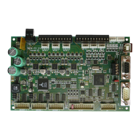
TMCM-351 Manual (V1.01 / May 25 , 2009) 4.2 Connectors The TMCM-351 has connectors for three motors, related reference switches, three encoders (only with encoder option), analogue and digital inputs and outputs and several serial interfaces (RS232, RS485, CAN and USB). -
Page 8: Power Connector
Table 4.2: Motor connector (detachable screw connector) Label Description Motor 0/1/2, coil B Motor_0/1/2_B- Motor_0/1/2_B+ Motor 0/1/2, coil B Motor_0/1/2_A- Motor 0/1/2, coil A Motor_0/1/2_A+ Motor 0/1/2, coil A Table 4.3: Motor connector (crimp connector) Copyright © 2008, TRINAMIC Motion Control GmbH & Co. KG... -
Page 9: Reference Connector
There are two connectors with two analogue inputs connected to each connector Label Description Analogue input 0 / 2 Analogue_0/2 System / module ground Analogue_1/3 Analogue input 1/3 System / module ground Table 4.6: Analogue input connector Copyright © 2008, TRINAMIC Motion Control GmbH & Co. KG... -
Page 10: Usb Connector
System / board ground n.c. Pins not used / not connected Table 4.9: CAN connector Attention: please verify setting of J3 (CAN bus termination) for proper operation of the CAN connection. Copyright © 2008, TRINAMIC Motion Control GmbH & Co. KG... -
Page 11: Rs485 Connector
(see picture on front page). Label Label OUT_0 OUT_1 OUT_2 OUT_3 OUT_4 OUT_5 OUT_6 OUT_7 +5V_output IN_0 IN_1 IN_2 IN_3 IN_4 IN_5 IN_6 IN_7 /Shutdown Table 4.12: I/O connector Copyright © 2008, TRINAMIC Motion Control GmbH & Co. KG... -
Page 12: Encoder_0/1/2 Connector
A standard 2.54mm pitch two row header is used for connecting an encoder. Differential and single ended incremental encoders with / without zero / index channel are supported. Label Label Encoder_0/1/2_N+ Encoder_0/1/2_N- Encoder_0/1/2_A+ Encoder_0/1/2_A- +5V_output +5V_output Encoder_0/1/2_B+ Encoder_0/1/2_B- Table 4.13: Encoder connector Copyright © 2008, TRINAMIC Motion Control GmbH & Co. KG... -
Page 13: Jumpers
Do not set these jumpers in case encoders with single ended signals are used. Place jumpers for proper temrination Copyright © 2008, TRINAMIC Motion Control GmbH & Co. KG... -
Page 14: Operational Ratings
°C current (no forced cooling required) Environment temperature at 80% of °C rated current or 50% duty cycle (no forced cooling required) Table 5.1: General operational ratings of the module Copyright © 2008, TRINAMIC Motion Control GmbH & Co. KG... -
Page 15: Revision History
Author Description 1.00 2008-10-22 Initial version 1.01 2009-05-25 Encoder input pinning corrected Table 6.1: Document Revision 6.2 Hardware Revision Version Date Description 1.00 2008-08-25 First prototypes Table 6.2: Hardware Revision Copyright © 2008, TRINAMIC Motion Control GmbH & Co. KG...
Need help?
Do you have a question about the TMCM-351 and is the answer not in the manual?
Questions and answers