Sign In
Upload
Manuals
Brands
RMG Manuals
Measuring Instruments
ERZ2000-NG
RMG ERZ2000-NG Manuals
Manuals and User Guides for RMG ERZ2000-NG. We have
1
RMG ERZ2000-NG manual available for free PDF download: Operating Manual
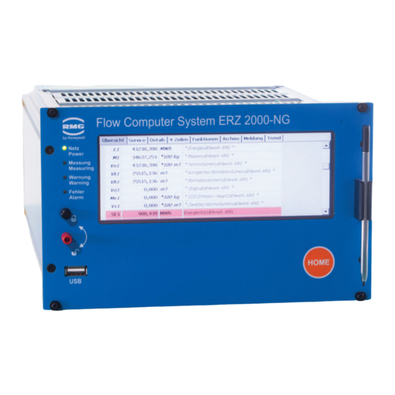
RMG ERZ2000-NG Operating Manual (454 pages)
Flow Computer
Brand:
RMG
| Category:
Measuring Instruments
| Size: 6.52 MB
Table of Contents
Table of Contents
3
About this Manual
11
Structure of the Manual
11
Purpose of the Manual
12
Abbreviations
12
Symbols
14
Structure of Notices
14
Working with the Device
15
Risk Assessment and Minimization
19
Applicability of the Manual
20
Transport
21
Scope of Delivery
21
Disposal of Packaging Material
22
Storage
22
Function
23
Overview
24
Areas of Application
25
Device Type Adjustment
26
Use in Gas Measurement Technology
27
Seal Diagram for Devices with MID Approval
29
Signature, Software and Hardware Data
32
Introduction
37
Operation
37
Front Panel
37
Operation on the Touch Screen
38
Remote Control / Parameterization
38
Live Browser and Coordinate System
44
Display
50
Access Protection for Data and Settings
56
Basic Settings
60
Start Screen
63
Overview
65
Service
78
Details
80
Lines
80
Functions
81
Archive
91
Alarm, Warning Message
94
Trend
96
Maximum Load
97
Time System
99
KA Times and Time Settings
99
KB Time Contact Signal to External Devices
102
KC External Time Signal
103
KD Plausibility
107
Electrical Connections
108
Equipment Variants
108
Configuration of Connections
110
Terminal Assignment
113
Data Interfaces
117
Pin Assignment and Recommened Use of the Interfaces
119
External Modem Connection
124
Connections
129
Activation of Inputs and Outputs
133
Assignment of "Physical Values
135
MA Input / Output Function Key
135
NA Current Input 1
138
NI Res. Input 1
139
NL Frequency Input 1
140
NT Contact Inputs
141
NU Current Input 9 Exi
142
NY Resistance Measuremnt 3
143
MB Current Output 1
144
MF Pulse Output 1
146
MJ Contact Output 1
149
MR Frequency Output 1
150
Revision Switch
151
Communication and Bus Systems
152
Bus Systems
152
Dsfg Bus
153
Modbus
156
Concept
156
Modbus Master Overview
158
NAMUR Sensor Adjustment (Optional)
168
Settings for Communication
169
IA TCP/IP Network
169
IC Dsfg Instance Computer
170
ID Dsfg Entity Recording
172
IE Remote Data Transmission Access
174
IF Dsfg Master
177
Transmitters
180
Measurements
181
Pressure Transducer
183
Temperature Transducer
190
AL Internal Temperature of the Device
191
Special Measurements
192
Flow Meters
193
General Settings
193
AQ 4-20 Ma Flow
193
GB Flow Rate Parameters
194
GC Kv Factor
203
GD Characteristic Curve Determination
204
GE Error Curve Linearisation, Forward Flow
206
GG Flow
210
GH Start-Up and Shut-Down Monitoring
210
HB Energy Flow
211
OO Extra Counter
212
Turbine Meter
213
EC Billing Mode
214
Ultrasonic Gas Meter
219
GJ Body Compensation
223
UA Ultrasonic Volume Transmitter
224
UB USZ Reynolds Correction
225
UC Base Correction
226
UD Err.curve Correction
226
UE Effects of Correct
227
UF ID Display IGM 1
228
UJ Path 1
229
VA Current Velocity of Gas
229
VB Speed of Sound
230
VC Ultrasonic Profile
231
VD Volume Flow
231
VE Messages
232
VF Signal Acceptance
232
VG Signal-To-Noise Ratio
233
VH Automatic Gain Control
234
Gas Speed Hourly Mean Value
234
LO Digital Totalizer Transmission
235
Connection of Uszs Via Instance F
236
Explanation of the Term Instance F
236
Modbus Communication with the USM GT400
237
Electrical Connection
237
USM GT400 Connection Area
237
Configuration for COM6 and COM7
238
Volume Transmitter Operating Mode
243
Protocol Type in Menu VJ Register Plots
244
COM6 Interface Configuration
245
Configuration VK Modbus According to Instance F
246
Configuration Menu VK for USM GT400 RS 485-1
247
Configuration USM GT400 for Instance F
248
Modbus Register for Instance F
250
OX Rmgview Trigger
255
Orifice Plate Diameter
256
GA Tube Dimensions
258
AP Diff.pressure
261
Special Case Zero Point Calibration of All Delta-P Cells
265
Parameter of the Gas
269
Direct Gas Parameters
269
BA Components Mode
269
BB Carbon Dioxide
271
BE Methane
272
Additional Gas Values
273
AD Superior Calorific Value
274
AE Standard Density
276
LU Quantity Weighted Average Values
277
AF Relative Density
278
AG Density
278
AH Temperature of the Density Transmitter
278
AI Temperature for VOS Correction
278
AJ Velocity of Sound at Measurement Conditions
279
AK Velocity of Sound at Base Conditions
279
AM Viscosity
279
AN Isentropic Exponent
279
AO Joule-Thomson Coefficient
279
C Analysis
281
CA Overview (Analysis Function Key)
281
CB Conversion Factor
282
CC Calculation of K Coefficient
283
Gerg 88 S
288
CE AGA NX 19 Equation of State
290
CH AGA 8 92DC Equation of State
291
CK Industrial Gases Parameter
292
CN C6+ -Distribution
293
D Calculated Values
294
DA Calculations According to ISO 6976
294
DB Calculation According to Aga10/Helmholtz ISO20765-1:2005
295
DC Transport Phenomena
296
DD Critical Values
296
DE Stoichiometry
297
DF Environment
297
DJ Exhaust Summary
298
DK Composition of Exhaust Fumes
300
DG Correction of Velocity of Sound
301
DH Assessed Analysis
302
DI Adjustable Extra Base Condition
303
DL Calculations According to GPA 2172-96
303
E-Z Additional Analysis-Specific Menus
304
EB Base Values
304
EF Processing Table Values
305
FE Calibration Unit Standard Density / Gross Calorific Value
306
Analysis-Specific Communication
307
IG Imported Gas Quality Via Dsfg
308
IJ Imp. GC Modbus Main
311
IK Imp. GC Modbus Ref
312
IL Modbus Master GC1
314
IM Modbus Master GC2
317
IH Imported Gas Quality Via RMG Bus
318
IP Modbus EGO Erdgas Ostschweiz
323
Overview: Coordinates
325
LS Hourly Quantities
325
Documentation
327
Check Numbers
327
Matrix
328
Document Creation
329
Documentation
330
Parameterization
331
Parameterizing Data
331
Calibration Data
332
Changes
333
Saving and Loading
334
Parameterization Help
335
Support for Inputting Components
335
Miscellaneous
336
Fault Display
336
Frozen Values
336
Interface Variables
337
View Log
338
Binary Code Check
339
TSV Export
340
Exceptions
342
Faults
343
Fault Settings
343
JA Fault Messages
343
JB Message Register
345
CJ GIA-Bit Table
346
JD Debugging
347
ON Extra Messages
348
Error Table
349
Appendix
361
Second PT100
361
Special Case of Revision with Orifice Flow Meter
363
Linking Extra Counter with Pulse Output
364
Linking Control Totalizer with Pulse Output
365
Test Functions
366
FA Control Panel
366
FB On-The-Fly Calibration
367
FC Freeze
367
FD Corrector Cycle
368
FF Function Test under Running Conditions
368
FG Hardware Test
370
FJ File System
371
FK Boole Function
372
B) Updating Software
373
Advance Information
373
Software Identification
373
Updating Software
374
Installing BIOS
376
Activation after Software Update
379
C) Archive Assignment, Depth and Identification
380
Archive Groups
380
OA Dsfg Archive
381
OC Function
382
OD Input Values
382
OE Miscellaneous
383
OU Freely Programmable Archive
384
OV Dialogs
385
OW Text for Browser
386
OY Special Values Dsfg
387
OZ Dsfg Archive Part 2
388
Archive Groups
388
Archive Depth
390
Archive Identifications
390
D) Determination of the Correction Factor for a Current Input
391
E) Various Circuit Diagrams for Inputs
392
F) Optional Ex Input Board
403
Instructions for the Installer
403
G) Various Circuit Diagrams for Outputs
405
H) Vo Digital Totalizer
406
I) Examples for Use of the Revision Switch
408
J) Appendix For Bus Systems
411
Dsfg Bus
411
Literature for the Dsfg Bus
411
Cross-Comparison Via Dsfg
411
Modbus
414
Summarized Fault Messages
414
Modbus EGO
419
J.2.2 Modbus EGO
419
Transgas Modbus
421
J.2.3 Transgas Modbus
421
Eon Gas Transport Modbus
423
K) Cross-References to Coordinates
424
A Measurements
424
B Components
426
K.2 B Components
426
C Analysis
428
K.3 C Analysis
428
D Calculation Values
429
K.4 D Calculation Values
429
E Mode
430
F Test
431
G Totalizer/Volume Transmitter
432
H Flow Rate
433
I Communication
434
J Fault Messages
435
K.10 J Fault Messages
435
K Times
436
K.11 K Times
436
L Totalizers
437
K.12 L Totalizers
437
M Outputs
439
K.13 M Outputs
439
N Inputs
441
K.14 N Inputs
441
O Miscellaneous
443
K.15 O Miscellaneous
443
P Highest Load
445
K.16 P Highest Load
445
Q Archive
446
K.17 Q Archive
446
T Trend
448
K.18 T Trend
448
U Igm
449
F Instance
451
K.20 V F Instance
451
Certificates
452
Advertisement
Advertisement
Related Products
RMG ERZ 2000
RMG EC 900
RMG EMC 500
RMG EMC 500-L
RMG ERZ2000-DI Series
RMG EC 24
RMG EC 21
RMG ENCO08
RMG ENCO08-M
RMG PGC 9300
RMG Categories
Measuring Instruments
Controller
Control Unit
Desktop
Timer
More RMG Manuals
Login
Sign In
OR
Sign in with Facebook
Sign in with Google
Upload manual
Upload from disk
Upload from URL