Table of Contents
Advertisement
Quick Links
Advertisement
Table of Contents

Related Manuals for Aaeon IMBM-Q87A


Summary of Contents for Aaeon IMBM-Q87A
- Page 1 IMBM-Q87A...
- Page 2 E8740 First Edition Nov. 2013 Copyright Notice This document is copyrighted, 2013. All rights are reserved. The original manufacturer reserves the right to make improvements to the products described in this manual at any time without notice. No part of this manual may be reproduced, copied, translated, or transmitted in any form or by any means without the prior written permission of the original manufacturer.
-
Page 3: Table Of Contents
Contents Chapter 1 Product overview Package contents ................. 1-1 Features ..................1-1 1.3 Specifications ................1-2 Chapter 2 Motherboard information Before you proceed ..............2-1 Motherboard layout ..............2-2 Screw size ..................2-4 2.3.1 Component side .............. 2-4 2.3.2 Solder side ..............2-5 Central Processing Unit (CPU) ........... - Page 4 3.3.2 Dynamic Digital IO ............3-4 3.3.3 ACPI Settings ..............3-4 3.3.4 Trusted Computing ............3-4 3.3.5 CPU Configuration ............3-5 3.3.6 SATA Configuration ............3-5 3.3.7 PCH-FW Configuration ........... 3-6 3.3.8 AMT Configuration ............3-6 3.3.9 USB Configuration ............3-6 3.3.10 F81216 Second Super IO Configuration ......
-
Page 5: Product Overview
Chapter 1 Product overview Package contents Check your industrial motherboard package for the following items. 1 x Industrial Motherboard 2 x SATA 6G cable 1 x I/O Shield 1 x COM port cable 1 x Support CD If any of the above items is damaged or missing, contact your distributor or sales representative immediately. -
Page 6: Specifications
9.6 in. x 9.6 in. (244 mm x 244 mm) Gross weight 1.76 lb (0.8 Kg) Operating F~140 F (0 C~60 temperature Storage temperature F~185 F (-40 C~85 Operating humidity 0%~90% relative humidity, non-condensing Power compliance Compliant with Eup/ErP Certificate CE/FCC (continued on the next page) IMBM-Q87A... - Page 7 DISPLAY Chipset Intel Graphics Media Accelerator ® Resolution Up to 1920x1200@60Hz for VGA Up to 1920x1200@60Hz for DVI Up to 2560x1440@60Hz for Display Port Output interface DVI-D+DP, DP+DP, VGA+DVI-D, VGA+DP, DVI-D+DP+DP, VGA+DP+DP Storage 5 x SATA 6.0Gb/s ports RAID 0 / 1 / 5 / 10 support Serial port 1 x RS-232/422/485 supports 5V/12V/RI on rear IO 5 x RS-232 header on mid-board...
- Page 8 IMBM-Q87A...
-
Page 9: Motherboard Information
Chapter 2 Motherboard information Before you proceed Take note of the following precautions before you install motherboard components or change any motherboard settings. CAUTION! • Unplug the power cord from the wall socket before touching any component. • Before handling components, use a grounded wrist strap or touch a safely grounded object or a metal object, such as the power supply case, to avoid damaging them due to static electricity. -
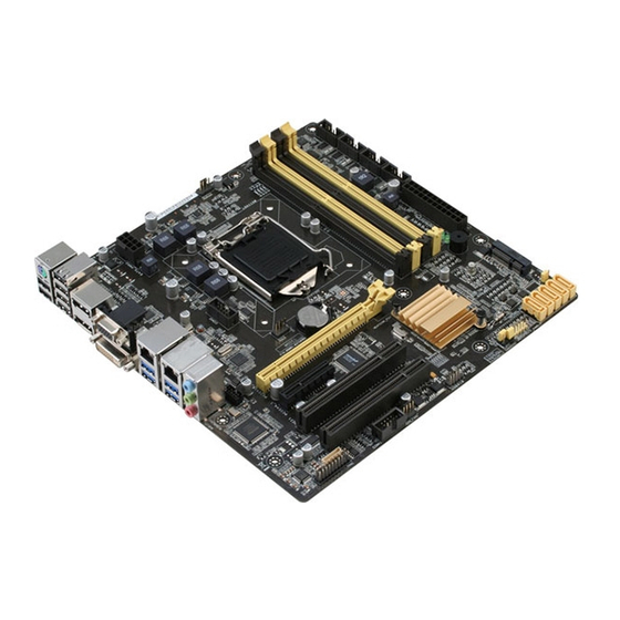
Page 10: Motherboard Layout
Place this side towards the rear of the chassis COM2 Intel ® I217LM LAN1_USB3_12 CPU_FAN1 LAN2_USB3_34 Intel ® SB_PWR1 I210AT SB_PWR2 AUDIO1 DIO1 PCIEX16_1 Nuvoton PCIEX4_1 NCT6791D Intel ® PCI1 COM1_V1 PCI2 DIS_ME TPM1 F_PANEL1 COM1 CHA_FAN2 USB910 CLRTC CHASSIS1 IMBM-Q87A... - Page 11 Connectors/Jumpers/LEDs Page ATX power connectors (24-pin EATXPWR1, 8-pin EATX_PWR2) 2-18 Serial port connectors (10-1 pin COM1~6) 2-21 CPU and system fan connectors (4-pin CPU_FAN1, 4-pin CHA_FAN1~2) 2-19 Intel LGA1150 CPU socket ® DIMM memory slots 2-11 Standby Power LED (SB_PWR1~2) 2-15 Minicard connector (MINICARD) 2-19...
-
Page 12: Screw Size
Screw size 2.3.1 Component side IMBM-Q87A... -
Page 13: Solder Side
2.3.2 Solder side Chapter 2: Motherboard information... -
Page 14: Central Processing Unit (Cpu)
The motherboard comes with a surface mount LGA1150 socket designed for the Intel® 4th Generation Core™ i7 / Core™ i5 / Core™ i3, Pentium®, Celeron® processors. IMBM-Q87A CPU socket LGA1150 IMPORTANT: Unplug all power cables before installing the CPU. CAUTION! •... -
Page 15: Installing The Cpu
2.4.1 Installing the CPU CAUTION! Ensure that you install the correct CPU designed for LGA 1150 only. DO NOT install a CPU designed for LGA1155 and LGA1156 sockets on the LGA1150 socket. Chapter 2: Motherboard information... - Page 16 IMBM-Q87A...
-
Page 17: Cpu Heatsink And Fan Assembly Installation
2.4.2 CPU heatsink and fan assembly installation CAUTION! Apply the Thermal Interface Material to the CPU heatsink and CPU before you install the heatsink and fan if necessary. To install the CPU heatsink and fan assembly Chapter 2: Motherboard information... - Page 18 To uninstall the CPU heatsink and fan assembly IMBM-Q87A 2-10...
-
Page 19: System Memory
DDR2 DIMM socket. DDR3 modules are developed for better performance with less power consumption. The figure below illustrates the location of the DDR3 DIMM sockets: IMBM-Q87A 240-pin DDR3 DIMM sockets Chapter 2: Motherboard information 2-11... -
Page 20: Installing A Dimm
2.5.1 Installing a DIMM To remove a DIMM IMBM-Q87A 2-12... -
Page 21: Jumpers
CMOS RTC RAM data. The onboard button cell battery powers the RAM data in CMOS, which include system setup information such as system passwords. IMBM-Q87A Clear RTC RAM To erase the RTC RAM: Turn OFF the computer and unplug the power cord. - Page 22 ® recovery mode when ME becomes corrupted. DIS_ME ME Enable ME Disable (Default) IMBM-Q87A Intel ME jumper ® COM1 VSET connector (COM1_V1) Com1_V1 PIN 1 +12V RI_VCC RI_VCC RI_VCC IMBM-Q87A COM VSET connector Setting Pins +12V Ring (Default) IMBM-Q87A 2-14...
-
Page 23: Onboard Leds
The illustration below shows the location of the onboard LEDs. SB_PWR1 Standby Power Powered Off SB_PWR2 Main Power Main Power Off IMBM-Q87A Onboard LEDs Chapter 2: Motherboard information 2-15... -
Page 24: Connectors
Line Out port (lime). This port connects to a headphone or a speaker. In a 4-channel, 6-channel and 8-channel configurations, the function of this port becomes Front Speaker Out. Microphone port (pink). This port connects a microphone. IMBM-Q87A 2-16... - Page 25 USB 3.0 ports (USB3_1234). These 9-pin Universal Serial Bus (USB) ports connect to USB 3.0/2.0 devices. NOTES: • DO NOT connect a keyboard / mouse to any USB 3.0 port when installing a Windows operating system. ® • Due to USB 3.0 controller limitations, USB 3.0 devices can only be used under a Windows OS environment and after USB 3.0 driver installation.
-
Page 26: Internal Connectors
+3 Volts +3 Volts +3 Volts PIN 1 IMBM-Q87A ATX power connectors IMPORTANT: • For a fully configured system, we recommend that you use a power supply unit (PSU) that complies with ATX 12 V Specification 2.0 (or later version) and provides a minimum power of 230W. - Page 27 CHA_FAN1 CPU_FAN1 CHA_FAN2 IMBM-Q87A Fan connectors CAUTION: Do not forget to connect the fan cables to the fan connectors. Insufficient air flow inside the system may damage the motherboard components. These are not jumpers! Do not place jumper caps on the fan...
- Page 28 PWR BTN PIN 1 +HD_LED RESET IMBM-Q87A System panel connector • System power LED (2-pin PWR_LED) This 2-pin connector is for the system power LED. Connect the chassis power LED cable to this connector. The system power LED lights up when you turn on the system power, and blinks when the system is in sleep mode.
- Page 29 PIN 1 COM1 PIN 1 PIN 1 IMBM-Q87A Serial port connectors NOTE: The COM module is purchased separately. Serial ATA 6.0Gb/s connector (7-pin SATA6G_1~5) ThIS connector connects to Serial ATA 6.0 Gb/s hard disk drives via Serial ATA 6.0 Gb/s signal cables.
- Page 30 480 Mbps connection speed. USB910 PIN 1 IMBM-Q87A Front USB 2.0 Header connector CAUTION: Never connect a 1394 cable to the USB connector. Doing so will damage the motherboard. NOTE: The USB module cable is purchased separately.
-
Page 31: Bios Setup
Chapter 3 BIOS setup BIOS setup program Use the BIOS Setup program to update the BIOS or configure its parameters. The BIOS screens include navigation keys and brief online help to guide you in using the BIOS Setup program. Entering BIOS Setup at startup To enter BIOS Setup at startup: Press <Delete>... -
Page 32: Bios Menu Screen
The Main menu provides you an overview of the basic system information, and allows you to set the system date, time, language, and security settings. 3.2.1 System Date [Day MM/DD/YYYY] Allows you to set the system date. 3.2.2 System Time [HH:MM:SS] Allows you to set the system time. IMBM-Q87A... -
Page 33: Advanced Menu
Advanced menu The Advanced menu items allow you to change the settings for the CPU and other system devices. Be cautious when changing the settings of the Advanced menu items. Incorrect field values can cause the system to malfunction. 3.3.1 S5 RTC Wake Settings Wake System with Fixed Time [Disabled] Enable or disable system wake on at an alarm event. -
Page 34: Dynamic Digital Io
This item selects the ACPI sleep state the system will enter when the system is in Suspend mode. Configuration options: [Suspend Disabled] [S3 only (Suspend to RAM)] 3.3.4 Trusted Computing Security Device Support [Disable] Allows you to enable or disable BIOS support for security devices. Configuration options: [Disable] [Enable] IMBM-Q87A... -
Page 35: Cpu Configuration
3.3.5 CPU Configuration The items in this menu show CPU-related information the BIOS automatically detects. The items shown in the submenu may be different depending on the type of CPU installed. Hyper-threading [Enabled] The Intel Hyper-Threading Technology allows a hyper-threading processor to appear as two logical processors to the operating system, allowing the operating system to schedule two threads or processes simultaneously. -
Page 36: Pch-Fw Configuration
[Enabled] to use a password. Configuration options: [Enabled] [Disabled] 3.3.9 USB Configuration The items in this menu allow you to change USB settings. The USB Devices lists detected USB devices. If no USB device is connected, the item shows None. IMBM-Q87A... -
Page 37: F81216 Second Super Io Configuration
Legacy USB Support [Enabled] [Enabled] Enables support for USB devices on legacy operating systems (OS). [Disabled] USB devices can only be in BIOS setup. [Auto] Allows the system to detect the presence of USB devices at startup. If detected, the USB controller legacy mode is enabled. -
Page 38: Nct6791D Hw Monitor
Fan Control Mode [Thermal Cruise Mode] Configuration options: [Manual Mode] [Thermal Cruise Mode] [Smart Fan IV Mode] The following items appear only when you set Fan Control Mode to [Thermal Cruise Mode]. Target Temperature [50] Input value range: [0~127] IMBM-Q87A... - Page 39 Tolerance of Temperature [0] Input value range: [0~7] Fan Out Start-Up Value [127] Input value range: [0~255] Fan Out Stop Value [100] The Fan Out value decreases to this value if the temperature reaches below the lowest temperature limit. Input value range: [0~255] Fan Out Stop Time [60] Determines the amount of time it takes for the the Fan Out value to fall from the stop value to zero.
- Page 40 Determines the amount of time Fan Out takes to increase its value by one step. Input value range: [0~255] Fan Out Step Down Time [10] Determines the amount of time Fan Out takes to decrease its value by one step in intervals of 0.1 seconds. Input value range: [0~255] IMBM-Q87A 3-10...
-
Page 41: Chipset Menu
Chipset menu The Chipset menu items allow you to change the settings for the chipset. 3.4.1 System Agent (SA) Configuration VT-d [Enabled] Allows you to enable or disable VT-d function on MCH. Configuration options: [Enabled] [Disabled] PCIex16 port Speed [Auto] Allows you to configure the PCIex16 speed. Configuration options: [Auto] [Gen1] [Gen2] [Gen3] Primary Display [Auto] Allows you to decide which graphics controller to use as the primary boot device. -
Page 42: Pch-Io Configuration
This item disables/enables ERP/EUP mode for energy star compliance. Configuration options: [Disabled] [Enabled] Intel WGI210AT Speed / Intel I217LM Speed / Asmedia ASM1085 Speed / PCIe x4 port Speed [Auto] Each item configures the speed of a specific PCI Express port. Configuration options: [Auto] [Gen1] [Gen2] IMBM-Q87A 3-12... -
Page 43: Boot Menu
Boot menu The Boot menu items allow you to change the system boot options. 3.5.1 Boot Configuration Quiet Boot [Enabled] This item enables/disables Quiet Boot. Configuration options: [Disabled] [Enabled] Launch I217LM PXE OpROM [Disabled] This item enables/disables Legacy Boot Option for I217LM. Configuration options: [Disabled] [Enabled] Launch WGI210AT PXE OpROM [Disabled] This item enables/disables Legacy Boot Option for WGI210AT. -
Page 44: Security Menu
Installed. After you set a password, this item shows Installed. To set a user password: Select the User Password item and press <Enter>. From the Create New Password box, key in a password, then press <Enter>. Confirm the password when prompted. IMBM-Q87A 3-14... - Page 45 To change a user password: Select the User Password item and press <Enter>. From the Enter Current Password box, key in the current password, then press <Enter>. From the Create New Password box, key in a new password, then press <Enter>.
-
Page 46: Save & Exit Menu
Click an item to start booting from the selected device. Launch EFI Shell from filesystem device This option allows you to attempt to launch the EFI Shell application (shellx64.efi) from one of the available devices that have a filesystem. IMBM-Q87A 3-16... -
Page 47: Appendix
Check local regulations for disposal of electronic products. DO NOT throw the mercury-containing button cell battery in municipal waste. This symbol of the crossed out wheeled bin indicates that the battery should not be placed in municipal waste. IMBM-Q87A Q87A... - Page 48 印 刷 電 路 板 及 其 × ○ ○ ○ ○ ○ 電子組件 外 部 信 號 連 接 頭 × ○ ○ ○ ○ ○ 及線材 ○: 表示該有毒有害物質在該部件所有均質材料中的含量均在 SJ/T 11363- 2006 標准規定的限量要求以下。 ×: 表示該有毒有害物質至少在該部件的某一均質材料中的含量超出 SJ/T 11363-2006 標准規定的限量要求,然該部件仍符合歐盟指令 2002/95/ E� 的規范。 備註:此產品所標示之環保使用期限,係指在一般正常使用狀況下。 IMBM-Q87A...
Need help?
Do you have a question about the IMBM-Q87A and is the answer not in the manual?
Questions and answers