Table of Contents
Advertisement
Advertisement
Table of Contents

Related Manuals for Aaeon IMBM-Q170A


Summary of Contents for Aaeon IMBM-Q170A
- Page 1 IMBM-Q170A...
- Page 2 E10898 First Edition November 2015 Copyright Notice This document is copyrighted, 2015. All rights are reserved. The original manufacturer reserves the right to make improvements to the products described in this manual at any time without notice. No part of this manual may be reproduced, copied, translated, or transmitted in any form or by any means without the prior written permission of the original manufacturer.
-
Page 3: Table Of Contents
Contents Chapter 1 Product overview Package contents................. 1-1 Features ..................1-1 Specifications ................1-2 Chapter 2 Motherboard information Before you proceed ..............2-1 Motherboard layout ..............2-2 Screw size ..................2-4 2.3.1 Component side .............. 2-4 2.3.2 Solder side ..............2-5 Central Processing Unit (CPU) ........... - Page 4 3.3.6 SIO Configuration ............3-5 3.3.7 NCT6791D HW Monitor ..........3-6 3.3.8 USB Configuration ............3-11 3.3.9 Digital IO Port Configuration ......... 3-12 3.3.10 Power Management ............3-12 Chipset menu ................3-14 3.4.1 System Agent (SA) Configuration ......... 3-14 3.4.2 PCH-IO Configuration ........... 3-14 Security menu ................3-15 3.5.1 Administrator Password ..........
-
Page 5: Chapter 1 Product Overview
Chapter 1 Product overview Package contents Check your industrial motherboard package for the following items. 1 x Industrial Motherboard 1 x SATA 6.0 Gb/s cable (2 in 1 pack) 1 x I/O Shield 1 x COM port cable (w/bracket) 1 x Support DVD If any of the above items is damaged or missing, contact your distributor or sales representative immediately. -
Page 6: Specifications
Micro-ATX 9.6” x 9.6” (244 mm x 244 mm) Gross weight 1.76 lb (0.8 Kg) Operating F~140 F (0 C~60 temperature Storage temperature F~185 F (-40 C~85 Operating humidity 0%~90% relative humidity, non-condensing Certificate CE/FCC (continued on the next page) IMBM-Q170A... - Page 7 DISPLAY Chipset Intel Graphics Media Accelerator ® Up to 1920 x 1200 @60Hz for VGA Resolution Up to 4096 x 2160 @24Hz for HDMI Up to 1920 x 1200 @24Hz for DVI-D VGA+HDMI, DVI-D+HDMI, HDMI+HDMI, DVI-D+HDMI+HDMI, Output interface VGA+HDMI+HDMI Storage 6 x SATA III (6.0Gb/s) ports, Supports RAID 0/1/5/10 1 x RS-232/422/485 (COM1, supports 5V/12V/RI optional) Serial port...
- Page 8 IMBM-Q170A...
-
Page 9: Chapter 2 Motherboard Information
Chapter 2 Motherboard information Before you proceed Take note of the following precautions before you install motherboard components or change any motherboard settings. CAUTION! • Unplug the power cord from the wall socket before touching any component. • Before handling components, use a grounded wrist strap or touch a safely grounded object or a metal object, such as the power supply case, to avoid damaging them due to static electricity. -
Page 10: Motherboard Layout
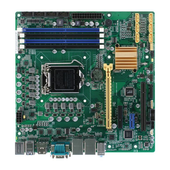
1442K Place this side 1442K towards the rear LGA1151 of the chassis LAN1_USB3_12 CHA_FAN1 LAN_USB3_34 Intel PHY I219LM AUDIO PCIEX16_1 BUZZER1 Intel I211AT IMBM-Q170A SB_PWR VS_PWR PCIEX4_1 Intel ® 128Mb Super BIOS Q170 SPI_1 1083 PCIEX1_1 SATA6G_1 SATA6G_2 SATA6G_3 PCI1... - Page 11 Connectors/Jumpers/LEDs Page CPU and system fan connectors (4-pin CPU_FAN1, 4-pin CHA_FAN1~2) 2-19 ATX power connectors (24-pin EATXPWR1, 8-pin EATX_PWR2) 2-18 Intel LGA1151 CPU socket ® DIMM memory slots 2-11 Serial port connectors (10-1 pin COM2~6) 2-21 Standby Power LED (VS_PWR / SB_PWR) 2-15 BIOS programmable connector (8-pin SPI1) 2-19...
-
Page 12: Screw Size
218.97 211.06 208.89 201.95 199.24 194.04 189.59 178.44 179.94 177.67 174.50 169.93 163.20 158.62 146.81 145.58 142.24 126.81 124.21 117.35 111.76 88.94 81.53 73.66 68.15 59.94 58.42 45.45 43.75 41.28 16.68 33.30 16.65 10.49 10.49 8.50 7.06 0.00 35.52 IMBM-Q170A... -
Page 13: Solder Side
2.3.2 Solder side 243.84 237.49 237.49 165.10 164.31 165.10 164.31 144.81 126.81 108.81 89.31 89.31 33.02 10.16 0.00 Chapter 2: Motherboard information... -
Page 14: Central Processing Unit (Cpu)
The motherboard comes with a surface mount LGA1151 socket designed for the Intel® 6th Generation Core™ i7 / Core™ i5 / Core™ i3, Pentium® and Celeron® 14nm processors. IMBM-Q170A IMBM-Q170A CPU socket LGA1151 IMPORTANT: Unplug all power cables before installing the CPU. CAUTION! •... -
Page 15: Installing The Cpu
2.4.1 Installing the CPU CAUTION! Ensure that you install the correct CPU designed for LGA 1151 only. DO NOT install a CPU designed for LGA1155 and LGA1156 sockets on the LGA1150 socket. Chapter 2: Motherboard information... - Page 16 IMBM-Q170A...
-
Page 17: Cpu Heatsink And Fan Assembly Installation
2.4.2 CPU heatsink and fan assembly installation CAUTION! Apply the Thermal Interface Material to the CPU heatsink and CPU before you install the heatsink and fan if necessary. To install the CPU heatsink and fan assembly Chapter 2: Motherboard information... - Page 18 To uninstall the CPU heatsink and fan assembly IMBM-Q170A 2-10...
-
Page 19: System Memory
DO NOT install a DDR, DDR2, or DDR3 memory module to the DDR4 slot. According to Intel CPU spec, DIMM voltage below 1.2 V is recommended to protect the ® CPU. IMBM-Q170A IMBM-Q170A 288-pin DDR4 DIMM sockets Chapter 2: Motherboard information 2-11... -
Page 20: Installing A Dimm
2.5.1 Installing a DIMM To remove a DIMM IMBM-Q170A 2-12... -
Page 21: Jumpers
IMBM-Q170A Normal Clear RTC (Default) IMBM-Q170A Clear RTC RAM To erase the RTC RAM: Turn OFF the computer and unplug the power cord. Move the jumper cap from pins 1-2 (default) to pins 2-3. Keep the cap on pins 2-3 for about 5~10 seconds, then move the cap back to pins 1-2. - Page 22 By default, the pin labeled “Chassis Signal” and “Ground” are shorted with a jumper cap. Remove the jumper caps only when you intend to use the chassis intrusion detection feature. CHASSIS IMBM-Q170A IMBM-Q170A Chassis intrusion connector IMBM-Q170A 2-14...
-
Page 23: Onboard Leds
The illustration below shows the location of the onboard LEDs. SB_PWR VS_PWR IMBM-Q170A Standby Power Powered Off Main Power Main Power Off IMBM-Q170A Onboard LEDs Chapter 2: Motherboard information 2-15... -
Page 24: Connectors
LED indications. LAN port LED indications Speed Activity Link ACT/LINK LED SPEED LED Status Description Status Description No link 10 Mbps connection ORANGE Linked ORANGE 100 Mbps LAN port connection BLINKING Data activity GREEN 1 Gbps connection IMBM-Q170A 2-16... - Page 25 Line In port (light blue). This port connects the tape, CD, DVD player, or other audio sources. Line Out port (lime). This port connects to a headphone or a speaker. In a 4-channel, 6-channel and 8-channel configurations, the function of this port becomes Front Speaker Out. Microphone port (pink). This port connects a microphone. USB 3.0 ports (USB3).
-
Page 26: Internal Connectors
+5 Volts +5 Volts PSON# IMBM-Q170A +3 Volts -12 Volts +3 Volts +3 Volts PIN 1 IMBM-Q170A ATX power connectors IMPORTANT: • For a fully configured system, we recommend that you use a power supply unit (PSU) that complies with ATX 12 V Specification 2.0 (or later version) and provides a minimum power of 330W. • We recommend that you use a PSU with higher power output when configuring a system with more power-consuming devices. The system may become unstable or may not boot up if the power is inadequate. - Page 27 These are not jumpers! Do not place jumper caps on the fan connectors! NOTE: The CPU_FAN connector supports a CPU fan of maximum 12V/2A fan rating. BIOS programmable connector (8-pin SPI1) Use this connector to flash the BIOS ROM. (NC) (NC) IMBM-Q170A SPI_SO_F SPI_SI_F SPI_CS0#_F SPI_CLK_F +V3.3SPI PIN 1 IMBM-Q170A BIOS Programmable connector Chapter 2: Motherboard information 2-19...
- Page 28 PWR BTN PIN 1 IMBM-Q170A +HDD_LED RESET IMBM-Q170A System panel connector • System power LED (2-pin PWR_LED) This 2-pin connector is for the system power LED. Connect the chassis power LED cable to this connector. The system power LED lights up when you turn on the system power, and blinks when the system is in sleep mode.
- Page 29 PIN 1 COM6 IMBM-Q170A PIN 1 IMBM-Q170A Serial port (COM) connectors NOTE: The COM module is purchased separately. Serial ATA 6.0Gb/s connector (7-pin SATA6G_1~6) These connectors connect to Serial ATA 6.0 Gb/s hard disk drives via Serial ATA 6.0 Gb/s signal cables.
- Page 30 USB1112 USB1314 PIN 1 PIN 1 IMBM-Q170A IMBM-Q170A USB2.0 connectors CAUTION: Never connect a 1394 cable to the USB connector. Doing so will damage the motherboard. NOTE: The USB module cable is purchased separately. 10. Speaker out connector (4-pin AMP_CON1) The 4-pin connector is for the chassis-mounted speaker.
-
Page 31: Chapter 3 Bios Setup
Chapter 3 BIOS setup BIOS setup program Use the BIOS Setup program to update the BIOS or configure its parameters. The BIOS screens include navigation keys and brief online help to guide you in using the BIOS Setup program. Entering BIOS Setup at startup To enter BIOS Setup at startup: Press <Delete> during the Power-On Self Test (POST). If you do not press <Delete>, POST continues with its routine. -
Page 32: Bios Menu Screen
The Main menu provides you an overview of the basic system information, and allows you to set the system date, time, language, and security settings. 3.2.1 System Date [Day MM/DD/YYYY] Allows you to set the system date. 3.2.2 System Time [HH:MM:SS] Allows you to set the system time. IMBM-Q170A... -
Page 33: Advanced Menu
Advanced menu The Advanced menu items allow you to change the settings for the CPU and other system devices. Be cautious when changing the settings of the Advanced menu items. Incorrect field values can cause the system to malfunction. 3.3.1 CPU Configuration The items in this menu show CPU-related information the BIOS automatically detects. -
Page 34: Sata Configuration
The items in this menu allow you to change the Intel Active Management ® Technology (AMT) feature. Intel AMT [Enabled] Allow you to enable or disable the Intel Active Management Technology (AMT) in ® the BIOS extension. Configuration options: [Enabled] [Disabled] iAMT H/W is always enabled. This option just controls the BIOS extension execution. If enabled, this requires additional firmware in the SPI device. IMBM-Q170A... -
Page 35: Pch-Fw Configuration
3.3.5 PCH-FW Configuration Firmware Update Configuration Me FW Image Re-Flash [Disabled] This item allows you to enable or disable Me FW Image Re-Flash function. Configuration options: [Disabled] [Enabled] 3.3.6 SIO Configuration The items in this menu allow you to configure Super IO settings. [*Active*] Serial Port 1 Use this device [Enabled] Allows you to enable or disable this logical device. Configuration options: [Enabled] [Disabled] The following two items appear only when you set Use this device to [Enabled]. -
Page 36: Nct6791D Hw Monitor
This item appears only when you set Use this device to [Enabled] and allows you to select an optimal setting for Super I/O devices. Configuration options: [Use Automatic Settings] [IO=2D0h; IRQ=11] [IO=2C0h; IRQ=11;] [*Active*] Serial Port 6 Use this device [Enabled] Allows you to enable or disable this logical device. Configuration options: [Enabled] [Disabled] Possible [Use Automatic Settings] Allows you to select an optimal setting for Super I/O devices. Configuration options: [Use Automatic Settings] [IO=2C0h; IRQ=11] [IO=2D0h; IRQ=11;] 3.3.7 NCT6791D HW Monitor The items in this menu allow you to configure the smart fan. IMBM-Q170A... - Page 37 Smart Fan Configuration CPU Smart Fan Control [Disabled] Allows you to enable or disable CPU Smart Fan Control. Configuration options: [Enabled] [Disabled] The following sub-items appear only when you set CPU Smart Fan Control to [Enabled]. Fan Control Mode [Manual Mode] Configuration options: [Manual Mode] [Thermal Cruise Mode] [Speed Cruise Mode] [Smart Fan IV Mode] The following item appears only when you set Fan Control Mode to [Manual Mode].
- Page 38 Fan PWM 1 [150] / Fan PWM 2 [170] / Fan PWM 3 [200] / Fan PWM 4 [220] Determines the amount of Fan PWM value for the Smart Fan IV mode Tolerance of Temperature [0] Input value range: [0~7] Critical Temperature [75] Input value range: [0~255] Critical Temp Tolerance [0] Input value range: [0~7] IMBM-Q170A...
- Page 39 Fan Count Step Up [5] Input value range: [0~15] Fan Count Step Down [5] Input value range: [0~15] Fan Out Step Up Time [10] Determines the amount of time Fan Out takes to increase its value by one step. Input value range: [0~255] Fan Out Step Down Time [10] Determines the amount of time Fan Out takes to decrease its value by one step in intervals of 0.1 seconds.
- Page 40 The following items appear only when you set Fan Control Mode to [Smart Fan IV Mode]. Temperature 1 [40] / Temperature 2 [50] / Temperature 3 [60] / Temperature 4 [70] Determines the temperature value for the Smart Fan IV mode. IMBM-Q170A 3-10...
-
Page 41: Usb Configuration
Fan PWM 1 [150] / Fan PWM 2 [170] / Fan PWM 3 [200] / Fan PWM 4 [220] Determines the amount of Fan PWM value for the Smart Fan IV mode. Tolerance of Temperature [0] Input value range: [0~7] Critical Temperature [75] Input value range: [0~255] Critical Temp Tolerance [0]... -
Page 42: Digital Io Port Configuration
T he system will wake up at the specified hr::min::sec. Configuration options: [Disabled] [Enabled] . [Dynamic Time] T he system will wake up at the current time plus a specified number of minutes. The following items appear when Fixed Time is enabled. Wake up day/hour/minute/second [0] Specify the values for day/hour/minute/second. The following item appears when Wake System with Dynamic Time is enabled. IMBM-Q170A 3-12... - Page 43 Wake up minute increase [1] Specify the number of minutes added to the current time before waking up system. Input value range: [1~5] Chapter 3: BIOS setup 3-13...
-
Page 44: Chipset Menu
Configuration options: [VBIOS Default] [HDMI 1] [DVI] [HDMI 2] [CRT] 3.4.2 PCH-IO Configuration HD Audio [Auto] This item controls the detection of HD Audio devices. Configuration options: [Disabled] [Enabled] [Auto] PCH LAN Controller [Enabled] This item allows you to enable or disable the onboard LAN controller. Configuration options: [Disabled] [Enabled] PCIEX1_1 Gen Speed [Auto] Configures the speed of PCI Express x1 slot. Configuration options: [Auto] [Gen1] [Gen2] [Gen3] PCIEX4_1 Gen Speed [Auto] Configures the speed of PCI Express x4 slot. Configuration options: [Auto] [Gen1] [Gen2] [Gen3] IMBM-Q170A 3-14... -
Page 45: Security Menu
Security menu The Security menu items allow you to change the system security settings. 3.5.1 Administrator Password If you have set an administrator password, we recommend that you enter the administrator password for accessing the system. Otherwise, you might be able to see or change only selected fields in the BIOS setup program. - Page 46 From the Create New Password box, key in a new password, then press <Enter>. Confirm the password when prompted. To clear the user password, follow the same steps as in changing a user password, but press <Enter> when prompted to create/confirm the password. After you clear the password, the User Password item on top of the screen shows Not Installed. IMBM-Q170A 3-16...
-
Page 47: Boot Menu
Boot menu The Boot menu items allow you to change the system boot options. 3.6.1 Boot Configuration Quiet Boot [Enabled] This item enables/disables Quiet Boot. Configuration options: [Disabled] [Enabled] Launch PXE ROM [Disabled] This item controls the execution of UEFI and Legacy PXE OpROM. Configuration options: [Disabled] [Enabled] 3.6.2 Boot Option Priorities These items specify the boot device priority sequence from the available devices. The number of device items that appears on the screen depends on the number of devices installed in the system. -
Page 48: Save & Exit Menu
Discard Changes & Reset This option allows you to exit the Setup program without saving your changes. When you select this option or if you press <Esc>, a confirmation window appears. Select Yes to discard changes and exit. Restore Defaults This option allows you to restore/load default values for all setup options. IMBM-Q170A 3-18... -
Page 49: Appendix
Check local regulations for disposal of electronic products. DO NOT throw the mercury-containing button cell battery in municipal waste. This symbol of the crossed out wheeled bin indicates that the battery should not be placed in municipal waste. IMBM-Q170A... - Page 50 印 刷 電 路 板 及 其 × ○ ○ ○ ○ ○ 電子組件 外 部 信 號 連 接 頭 × ○ ○ ○ ○ ○ 及線材 ○: 表示該有毒有害物質在該部件所有均質材料中的含量均在 SJ/T 11363- 2006 標准規定的限量要求以下。 ×: 表示該有毒有害物質至少在該部件的某一均質材料中的含量超出 SJ/T 11363-2006 標准規定的限量要求,然該部件仍符合歐盟指令 2002/95/ EC 的規范。 備註:此產品所標示之環保使用期限,係指在一般正常使用狀況下。 IMBM-Q170A...
Need help?
Do you have a question about the IMBM-Q170A and is the answer not in the manual?
Questions and answers