Table of Contents
Advertisement
Quick Links
Advertisement
Table of Contents

Related Manuals for Aaeon IMBA-H110A


Summary of Contents for Aaeon IMBA-H110A
- Page 1 IMBA-H110A E13195_IMBA-H110A_Guide.indb 1 2017/9/25 14:05:08...
- Page 2 E13521 Revised Edition September 2017 Copyright Notice This document is copyrighted, 2017. All rights are reserved. The original manufacturer reserves the right to make improvements to the products described in this manual at any time without notice. No part of this manual may be reproduced, copied, translated, or transmitted in any form or by any means without the prior written permission of the original manufacturer.
-
Page 3: Table Of Contents
Contents Chapter 1: Product overview Package contents ................. 1-1 Features ..................1-1 1.3 Specifications ................1-2 Chapter 2: Motherboard information Before you proceed ..............2-1 Motherboard layout ..............2-2 Screw size ..................2-4 2.3.1 Component side .............. 2-4 2.3.2 Solder side ..............2-5 Central Processing Unit (CPU) ........... - Page 4 3.4.1 System Agent (SA) Configuration ......... 3-10 3.4.2 PCH-IO Configuration ........... 3-11 Security menu ................3-11 3.5.1 Administrator Password ..........3-11 3.5.2 User Password .............. 3-12 Boot menu .................. 3-12 3.6.1 Boot Configuration ............3-12 3.6.2 Boot Option Priorities ............ 3-13 Save & Exit menu ............... 3-13 Appendix Notices .......................A-1 E13195_IMBA-H110A_Guide.indb 4...
-
Page 5: Chapter 1: Product Overview
Chapter 1 Product overview Package contents Check your industrial motherboard package for the following items. 1 x Industrial Motherboard 1 x SATA 6.0Gb/s cable 1 x COM cable 1 x I/O Shield 1 x Support CD If any of the above items is damaged or missing, contact your distributor or sales representative immediately. -
Page 6: Specifications
0%~90% relative humidity, non-condensing Certificate CE & FCC class A Form factor ATX form factor: 12 in. x 9.6 in. (305 mm x 244 mm) Weight 1.76 lb (0.8 Kg) (continued on the next page) IMBA-H110A E13195_IMBA-H110A_Guide.indb 2 2017/9/25 14:05:08... - Page 7 Back I/O 4 x USB 3.0 ports 2 x USB 2.0 ports Display 1 x HDMI ports 1 x VGA port 1 x Disaplay port Serial port 1 x RS-232/422/485 COM port (COM1, supports 5V/12V/RI, optional) PS/2 port 1 x PS/2 stack port (keyboard & mouse) 2 x LAN (RJ-45) ports Audio 3 x Audio jacks: Line-in, Mic-in, Line-out...
- Page 8 IMBA-H110A E13195_IMBA-H110A_Guide.indb 4 2017/9/25 14:05:08...
-
Page 9: Chapter 2: Motherboard Information
Chapter 2 Motherboard information Before you proceed Take note of the following precautions before you install motherboard components or change any motherboard settings. CAUTION! • Unplug the power cord from the wall socket before touching any component. • Before handling components, use a grounded wrist strap or touch a safely grounded object or a metal object, such as the power supply case, to avoid damaging them due to static electricity. • Hold components by the edges to avoid touching the ICs on them. • Whenever you uninstall any component, place it on a grounded antistatic pad or in the bag that came with the component. -
Page 10: Motherboard Layout
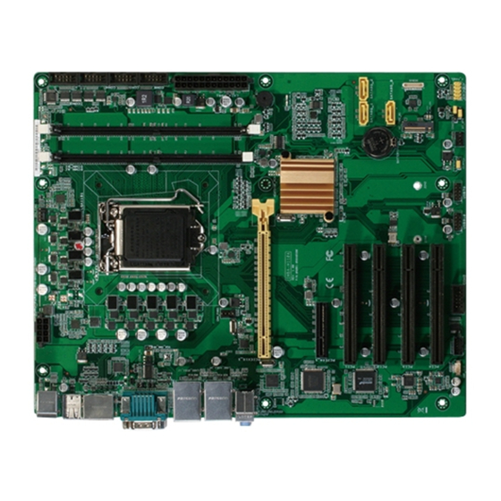
Place this side 2168 towards the rear of the chassis LAN1_USB3_12 CHA_FAN1 LAN2_USB3_34 Intel ® PHY i219V AUDIO1 PCIEX16_1 BUZZER1 Intel ® i211AT IMBA-H110A Intel ® SPI_1 Super 128Mb H110 BIOS PCIEX4 PCI1 SATA6G_1 SATA6G_2 1085 PCI2 SATA6G_3 PCI3 2280... - Page 11 Connectors/Jumpers/Slots Page COM1 operating mode selection jumpers (2-pin J1/J2/J3/J4) 2-13 ATX power connectors (24-pin EATXPWR1, 8-pin EATX_PWR2) 2-17 COM1 Ring/+5V/+12V selection jumper (6-pin COM1_V1) 2-13 CPU and chassis fan connectors (4-pin CPU_FAN1, 4-pin CHA_FAN1/2) 2-18 Intel LGA1151 CPU socket ® DDR4 DIMM slots 2-10 Serial port connectors (10-1pin COM2~6) 2-21 BIOS programmable connector (8-pin SPI_1) 2-19 M.2 M-Key slot 2-22 10. Serial ATA 6.0Gb/s connectors (7-pin SATA6G_1~3) 2-18 11. System panel connector (10-1 pin F_PANEL) 2-20 12. AT/ATX mode selection (3-pin AT_ATX) 2-14 13. Chassis intrusion jumper (4-1 pin CHASSIS) 2-14 14. Clear RTC RAM (3-pin CLRTC1) 2-12 15. USB 2.0 connectors (10-1 pin USB78 and USB910) 2-19 16. Digital I/O connector (10-pin DIO) 2-22 17.
-
Page 12: Screw Size
212.85 210.42 210.31 199.24 203.45 200.41 193.80 179.94 177.17 163.85 163.20 154.31 146.81 133.35 126.81 125.85 78.49 73.66 68.15 46.74 49.40 45.45 41.28 21.99 38.77 16.68 33.56 14.63 11.84 10.49 7.36 7.06 5.85 0.00 35.52 IMBA-H110A E13195_IMBA-H110A_Guide.indb 4 2017/9/25 14:05:10... -
Page 13: Solder Side
2.3.2 Solder side 243.84 237.49 237.49 165.10 165.10 164.31 144.81 126.81 108.81 89.31 33.02 10.16 0.00 Chapter 2: Motherboard information E13195_IMBA-H110A_Guide.indb 5 2017/9/25 14:05:10... -
Page 14: Central Processing Unit (Cpu)
Central Processing Unit (CPU) This motherboard comes with an Intel 7th/ 6th Generation Core™ i7 / i5 / i3, ® Pentium and Celeron 14nm LGA 1151 socket processor. ® ® IMBA-H110A IMBA-H110A CPU socket LGA1151 IMPORTANT: Unplug all power cables before installing the CPU. CAUTION! • Upon purchase of the motherboard, ensure that the PnP cap is on the socket and the socket contacts are not bent. Contact your retailer immediately if the PnP cap is missing, or if you see any damage to the PnP cap/socket contacts/motherboard components. • Keep the cap after installing the motherboard. The manufacturer will process Return Merchandise Authorization (RMA) requests only if the motherboard comes with the cap on the LGA1151 socket. • The product warranty does not cover damage to the socket contacts resulting from incorrect CPU installation/removal, or misplacement/loss/ incorrect removal of the PnP cap. IMBA-H110A E13195_IMBA-H110A_Guide.indb 6 2017/9/25 14:05:11... -
Page 15: Installing The Cpu
2.4.1 Installing the CPU CAUTION! Ensure that you install the correct CPU designed for LGA1151 only. DO NOT install a CPU designed for LGA1155 and LGA1156 sockets on the LGA1151 socket. Chapter 2: Motherboard information E13195_IMBA-H110A_Guide.indb 7 2017/9/25 14:05:11... - Page 16 IMBA-H110A E13195_IMBA-H110A_Guide.indb 8 2017/9/25 14:05:11...
-
Page 17: Cpu Heatsink And Fan Assembly Installation
2.4.2 CPU heatsink and fan assembly installation CAUTION! Apply the Thermal Interface Material to the CPU heatsink and CPU before you install the heatsink and fan if necessary. To install the CPU heatsink and fan assembly Chapter 2: Motherboard information E13195_IMBA-H110A_Guide.indb 9 2017/9/25 14:05:12... -
Page 18: System Memory
To uninstall the CPU heatsink and fan assembly System memory This motherboard comes with two Double Data Rate 4 (DDR4) Dual Inline Memory Modules (DIMM) sockets. The figure illustrates the location of the DDR4 DIMM sockets: IMBA-H110A IMBA-H110A 288-pin DDR4 DIMM sockets IMBA-H110A 2-10 E13195_IMBA-H110A_Guide.indb 10 2017/9/25 14:05:12... -
Page 19: Installing A Dimm
Installing a DIMM To remove a DIMM Chapter 2: Motherboard information 2-11 E13195_IMBA-H110A_Guide.indb 11 2017/9/25 14:05:13... -
Page 20: Jumpers
Clear RTC RAM (3-pin CLRTC1) This jumper allows you to clear the Real Time Clock (RTC) RAM in CMOS. You can clear the CMOS memory of system setup parameters by erasing the CMOS RTC RAM data. The onboard button cell battery powers the RAM data in CMOS, which include system setup information such as system passwords. IMBA-H110A CLRTC1 Normal Clear RTC (Default) IMBA-H110A Clear RTC RAM To erase the RTC RAM: 1. Turn OFF the computer and unplug the power cord. 2. Move the jumper cap from pins 1-2 (default) to pins 2-3. Keep the cap on pins 2-3 for about 5~10 seconds, then move the cap back to pins 1-2. 3. Plug the power cord and turn ON the computer. 4. Hold down the <Del> key during the boot process and enter BIOS setup to reenter data. CAUTION! Except when clearing the RTC RAM, never remove the cap on CLRTC jumper default position. Removing the cap will cause system boot failure! NOTES: •... - Page 21 COM1 Ring/+5V/+12V selection jumper (6-pin COM1_V1) COM1_V1 +12V Ring IMBA-H110A (Default) IMBA-H110A COM1 Ring/+5V/+12V Selection Setting Pins +12V Ring (Default) COM1 operating mode selection jumpers (2-pin J1/J2/J3/J4) J1、J2、J3、J4 RS232 (Default) RS485/RS422 with terminator IMBA-H110A IMBA-H110A COM1 RS422/RS485 Terminator (J1、J2、J3、J4) Setting Pins...
- Page 22 AT/ATX mode selection (3-pin AT_ATX) IMBA-H110A AT_ATX ATX mode AT mode (Default) IMBA-H110A H/W AT/ATX mode selection Pins ATX mode (Default) AT mode Chassis intrusion jumper (4-1 pin CHASSIS) This connector is for a chassis-mounted intrusion detection sensor or switch. Connect one end of the chassis intrusion sensor or switch cable to this connector. The chassis intrusion sensor or switch sends a high-level signal to this connector when a chassis component is removed or replaced. The signal is then generated as a chassis intrusion event.
-
Page 23: Connectors
Connectors 2.7.1 Rear panel connectors PS/2 mouse port (green). This port is for a PS/2 mouse. USB 2.0 ports. These 9-pin Universal Serial Bus (USB) ports connect to USB 2.0 devices. DisplayPort. This port is for a DisplayPort-compatible devices. Serial port (COM port). This port connects to a modem, or other device that conforms with serial specification. Serial Port Connector for Serial Port Connector for ( COM1 / RS485 ) ( COM1 / RS422 ) RS422 RX (B) RS422 RX(A) RS422 TX (A) RS485 D+ (A) - Page 24 NOTES: • DO NOT connect a keyboard / mouse to any USB 3.0 port when installing a Windows operating system. ® • Windows 7 requires USB 3.0 driver to use USB 3.0 devices. ® • We strongly recommend that you connect USB 3.0 devices to USB 3.0 ports for a faster and better performance from your USB 3.0 devices. 10. Video Graphics Adapter (VGA) port. This 15-pin port is for a VGA monitor or other VGA-compatible devices. 11. HDMI port. This port is for a High-Definition Multimedia Interface (HDMI) connectors, and is HDCP compliant allowing playback of HD DVD, Blu-Ray, and other protected content. 12. PS/2 keyboard port (purple). This port is for a PS/2 keyboard. IMBA-H110A 2-16 E13195_IMBA-H110A_Guide.indb 16 2017/9/25 14:05:14...
-
Page 25: Internal Connectors
Power OK -5 Volts PIN 1 +5 Volts IMBA-H110A +5 Volts PSON# +3 Volts -12 Volts +3 Volts +3 Volts PIN 1 IMBA-H110A ATX power connectors IMPORTANT: • For a fully configured system, we recommend that you use a power supply unit (PSU) that complies with ATX 12 V Specification 2.0 (or later version) and provides a minimum power of 230W. • We recommend that you use a PSU with higher power output when configuring a system with more power-consuming devices. The system may become unstable or may not boot up if the power is inadequate. Speaker out connector (4-pin AMP_CON) The 4-pin connector is for the chassis-mounted speaker. - Page 26 CPU_FAN1 CHA_FAN1 SENSE IMBA-H110A CHA_FAN2 IMBA-H110A Fan connectors CAUTION: Do not forget to connect the fan cables to the fan connectors. Insufficient air flow inside the system may damage the motherboard components. These are not jumpers! Do not place jumper caps on the fan connectors! Serial ATA 6.0Gb/s connectors (7-pin SATA6G_1~3) These connectors connect to Serial ATA 6.0 Gb/s hard disk drives via Serial...
- Page 27 7 in the Skylake platform: ® Step1. U se this utility to pack XHCI driver into the original Windows 7 OS ® image, there will be another OS image released. Step2. Use the new OS image to install via any device. BIOS programmable connector (8-pin SPI_1) Use this connector to flash the BIOS ROM. SPI_1 IMBA-H110A (NC) (NC) S_SPI_MISO_2Q S_SPI_MOSI_2Q S_SPI_CS1#Q S_SPI_CLK_2Q +3V_SPI PIN 1 IMBA-H110A BIOS Programmable connector Chapter 2: Motherboard information 2-19 E13195_IMBA-H110A_Guide.indb 19 2017/9/25 14:05:14...
- Page 28 System panel connectors (10-1 pin F_PANEL) This connector supports several chassis-mounted functions. F_PANEL +PWR LED PWR BTN PIN 1 IMBA-H110A +HDD_LED RESET IMBA-H110A Front panel connector • System power LED (2-pin PWR_LED) This 2-pin connector is for the system power LED. Connect the chassis power LED cable to this connector. The system power LED lights up when you turn on the system power, and blinks when the system is in sleep mode. • Hard disk drive activity LED (2-pin HDD_LED) This 2-pin connector is for the HDD Activity LED. Connect the HDD Activity LED cable to this connector. The IDE LED lights up or flashes when data is read from or written to the HDD.
- Page 29 Serial port connectors (10-pin COM2~6) These connectors are for serial (COM) ports. Connect the serial port module cable to this connector, then install the module to a slot opening at the back of the system chassis. COM3 PIN 1 COM4 COM2 PIN 1 PIN 1 COM5 PIN 1 COM6 IMBA-H110A PIN 1 IMBA-H110A Serial port (COM) connectors NOTE: The COM module is purchased separately. Chapter 2: Motherboard information 2-21 E13195_IMBA-H110A_Guide.indb 21 2017/9/25 14:05:15...
- Page 30 Digital I/O connector (10-pin DIO) This connector includes 8 I/O lines (In/Out programmable). All of the Digital I/O lines are programmable and each I/O pin can be individually programmed to support various devices. DIO1 IMBA-H110A PIN 1 IMBA-H110A Digitial I/O connector NOTE: To configure the I/O pins in BIOS, go to the Advanced tab > Digital IO Port Configuration. See section 3.3.8 Digital IO Port Configuration for details. 10. M.2 M-Key slot This socket allows you to install an M.2 (NGFF) SSD module. M2_TYPE_M1(SOCKET3) IMBA-H110A 2280 IMBA-H110A M.2(SOCKET3) NOTES: • The M.2 SSD module is purchased separately. • The M.2 M-key slot supports type 2280 SATA devices. IMBA-H110A 2-22 E13195_IMBA-H110A_Guide.indb 22...
-
Page 31: Chapter 3: Bios Setup
Chapter 3 BIOS setup BIOS setup Use the BIOS Setup to update the BIOS or configure settings. The BIOS screens include navigation keys and help to guide you in using the BIOS Setup program. Entering BIOS Setup at startup To enter BIOS Setup at startup: Press <Delete>... -
Page 32: Main Menu
Be cautious when changing the settings of the Advanced menu items. Incorrect field values can cause the system to malfunction. Case Open Warning [Disabled] Allows you to enable or disable case open warning function. Configuration options: [Disabled] [Enabled] [Clear] IMBA-H110A E13195_IMBA-H110A_Guide.indb 2 2017/9/25 14:05:16... -
Page 33: Cpu Configuration
3.3.1 CPU Configuration The items in this menu show CPU-related information the BIOS automatically detects. The items shown in the submenu may be different depending on the type of CPU installed. Hyper-threading [Enabled] The Intel Hyper-Threading Technology allows a hyper-threading processor to appear as two logical processors to the operating system, allowing the operating system to schedule two threads or processes simultaneously. -
Page 34: Sata Configuration
Allows you to set the working mode of the SATA controller. Configuration options: [AHCI] Port 1, Port 2, Port 3, Port 4 [Enabled] These items allow you to enable/disable the SATA port(s). Configuration options: [Disabled] [Enabled] IMBA-H110A E13195_IMBA-H110A_Guide.indb 4 2017/9/25 14:05:16... -
Page 35: Pch-Fw Configuration
Hot Plug [Disabled] These items allow you to enable/disable SATA Hot Plug Support. Configuration options: [Disabled] [Enabled] 3.3.4 PCH-FW Configuration Firmware Update Configuration Me FW Image Re-Flash [Disabled] This item allows you to enable or disable Me FW Image Re-Flash function. Configuration options: [Disabled] [Enabled] Local FM Update [Enabled] This item allows you to enable or disable Local FM Update function. -
Page 36: Nct6791D Hw Monitor
CPU Smart Fan Control, CHA Smart Fan1 Control, CHA Smart Fan2 Control [Enabled] Allows you to enable or disable CPU Smart Fan/CHA Smart Fan1/CHA Smart Fan2 Control. Configuration options: [Enabled] [Disabled] The following sub-items appear only when you set CPU Smart Fan Control to [Enabled]. IMBA-H110A E13195_IMBA-H110A_Guide.indb 6 2017/9/25 14:05:16... - Page 37 Fan Control Mode [Smart Fan IV Mode] Configuration options: [Manual Mode] [Thermal Cruise Mode] [Speed Cruise Mode] [Smart Fan IV Mode] The following items appear only when you set Fan Control Mode to [Smart Fan IV Mode]. Temperature 1 [40] / Temperature 2 [50] / Temperature 3 [60] / Temperature 4 [70] Sets the temperature value for the Smart Fan IV mode.
- Page 38 Cruise Mode]. Target Speed [0] Input value range: [0~4096] Speed Tolerance [2] Input value range: [0~64] Fan Out Step Up Time [10] Input value range: [0~255] Fan Out Step Down Time [10] Input value range: [0~255] IMBA-H110A E13195_IMBA-H110A_Guide.indb 8 2017/9/25 14:05:16...
-
Page 39: Usb Configuration
3.3.7 USB Configuration The USB Devices item lists auto-detected values. If no USB device is detected, the item shows None. Legacy USB Support [Enabled] [Enabled] Enables the support for USB devices on legacy operating systems (OS). [Disabled] USB devices are only available when running BIOS Setup. [Auto] Allows the system to detect the presence of USB devices at startup. -
Page 40: Chipset Menu
The secondary boot display selection appears based on your selection and the VGA mode is supported only on primary display. Configuration options: [VBIOS Default] [DP] [HDMI] [VGA] IMBA-H110A 3-10 E13195_IMBA-H110A_Guide.indb 10 2017/9/25 14:05:16... -
Page 41: Pch-Io Configuration
PCIEX16_1 Gen Speed [Auto] Allows you to configure the PEG 0:1:0 maximum speed. Configuration options: [Auto] [Gen1] [Gen2] [Gen3] 3.4.2 PCH-IO Configuration HD Audio [Auto] This item controls the detection of HD Audio devices. Configuration options: [Auto] [Disabled] [Enabled] PCIEX4_1 Gen Speed [Auto] Configures the speed of PCIe x4 slot 1. -
Page 42: User Password
Quiet Boot [Enabled] This item enables/disables Quiet Boot. Configuration options: [Disabled] [Enabled] Launch PXE ROM [Do not launch] This item controls the execution of UEFI and Legacy PXE OpROM. Configuration options: [Do not launch] [Legacy] IMBA-H110A 3-12 E13195_IMBA-H110A_Guide.indb 12 2017/9/25 14:05:16... -
Page 43: Boot Option Priorities
3.6.2 Boot Option Priorities These items specify the boot device priority sequence from the available devices. The number of device items that appears on the screen depends on the number of devices installed in the system. Save & Exit menu Save Changes and Reset Once you are finished making your selections, choose this option from the Save &... - Page 44 IMBA-H110A 3-14 E13195_IMBA-H110A_Guide.indb 14 2017/9/25 14:05:16...
-
Page 45: Appendix
Check local regulations for disposal of electronic products. DO NOT throw the mercury-containing button cell battery in municipal waste. This symbol of the crossed out wheeled bin indicates that the battery should not be placed in municipal waste. IMBA-H110A E13195_IMBA-H110A_Guide.indb 1 2017/9/25 14:05:16... - Page 46 外部信號連接頭 × ○ ○ ○ ○ ○ 及線材 中央處理器與內 × ○ ○ ○ ○ ○ 存 本表格依據 SJ/T 11364 的規定編制。 ○: 表示該有害物質在該部件所有均質材料中的含量均在 GB/T 26572 規 定的限量要求以下。 ×: 表示該有害物質至少在該部件的某一均質材料中的含量超出 GB/T 26572 規定的限量要求,然該部件仍符合歐盟指令 2011/65/EU 的 規范。 備註:此產品所標示之環保使用期限,係指在一般正常使用狀況下。 IMBA-H110A E13195_IMBA-H110A_Guide.indb 2 2017/9/25 14:05:16...
Need help?
Do you have a question about the IMBA-H110A and is the answer not in the manual?
Questions and answers