Table of Contents
Advertisement
I n d u s t r i a l M o t h e r b o a r d
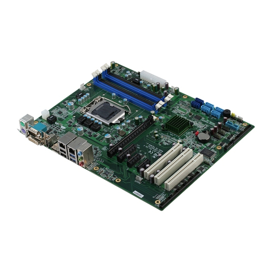
I M B A - Q 7 7
IMBA-Q77
®
TM
Intel
3rd Generation Core
i3/i5/i7
Processor
DDR3 1066/1333 MHz DIMM
2 SATA 6.0Gb/s, 4 SATA 3.0Gb/s
1 PCI-Express[x16], 1 PCI-Express[x4]
2 PCI-Express[x1], 3 PCI
4 USB3.0, 8 USB2.0, 6 COM, 1 LPT
VGA, 1 DVI-D, 2 DisplayPort™
rd
IMBA-Q77 Manual Rev.A 3
Ed.
March 14, 2016
Advertisement
Table of Contents

Related Manuals for Aaeon IMBA-Q77


Summary of Contents for Aaeon IMBA-Q77
- Page 1 Processor DDR3 1066/1333 MHz DIMM 2 SATA 6.0Gb/s, 4 SATA 3.0Gb/s 1 PCI-Express[x16], 1 PCI-Express[x4] 2 PCI-Express[x1], 3 PCI 4 USB3.0, 8 USB2.0, 6 COM, 1 LPT VGA, 1 DVI-D, 2 DisplayPort™ IMBA-Q77 Manual Rev.A 3 March 14, 2016...
-
Page 2: Copyright Notice
AAEON assumes no liabilities resulting from errors or omissions in this document, or from the use of the information contained herein. AAEON reserves the right to make changes in the product design without notice to its users. - Page 3 I n d u s t r i a l M o t h e r b o a r d I M B A - Q 7 7 Acknowledgments All other products’ name or trademarks are properties of their respective owners.
-
Page 4: Packing List
COM Port Cable • USB2.0 Cable • DVD-ROM for Manual (in PDF Format) and Drivers • IO Shield for IMBA-Q77 main board If any of these items should be missing or damaged, please contact your distributor or sales representative immediately. -
Page 5: Table Of Contents
I n d u s t r i a l M o t h e r b o a r d I M B A - Q 7 7 Contents Chapter 1 General Information 1.1 Introduction ..............1-2 1.2 Features ..............1-3 1.3 Specifications ............ - Page 6 I n d u s t r i a l M o t h e r b o a r d I M B A - Q 7 7 Chapter 3 AMI BIOS Setup 3.1 System Test and Initialization........3-2 3.2 AMI BIOS Setup ............
-
Page 7: Chapter 1 General Information
I n d u s t r i a l M o t h e r b o a r d I M B A - Q 7 7 Chapter General Information 1- 1 Chapter 1 General Information... -
Page 8: Introduction
8 USB2.0, 4 USB3.0, 6 COM, two PS/2 ports, and multiple extended bus for a flexible expansion selection. The storage of IMBA-Q77 supports four SATA 3.0 Gb/s and two SATA 6.0 Gb/s to support RAID 0, 1, 5, 10 functions. -
Page 9: Features
I n d u s t r i a l M o t h e r b o a r d I M B A - Q 7 7 1.2 Features ® Intel Generation Core™ i7/ i5/ i3 LGA 1155 Processor ®... -
Page 10: Specifications
I n d u s t r i a l M o t h e r b o a r d I M B A - Q 7 7 1.3 Specifications System Form Factor ® Processor Intel generation Core™ i3/i5/i7 LGA 1155 Processor ... - Page 11 I n d u s t r i a l M o t h e r b o a r d I M B A - Q 7 7 1.2 onboard (optional) Power Requirement ATX standard 24-pin connector x 1, 4-pin +12V connector x 1, CPU fan x 1, system fan x 1 with 4-pin wafer, supports SMART FAN...
- Page 12 I n d u s t r i a l M o t h e r b o a r d I M B A - Q 7 7 I/O: Winbond W83627DHG-P + Fintek F81216AD Storage SATA 3.0 Gb/s x 4, SATA 6.0 Gb/s x 2, support RAID 0,1,5,10 ...
-
Page 13: Chapter 2 Quick Installation Guide
I n d u s t r i a l M o t h e r b o a r d I M B A - Q 7 7 Chapter Quick Installation Guide 2 - 1 Chapter 2 Quick Installation Guide... -
Page 14: Safety Precautions
I n d u s t r i a l M o t h e r b o a r d I M B A - Q 7 7 2.1 Safety Precautions Always completely disconnect the power cord from your board whenever you are working on it. -
Page 15: Location Of Connectors And Jumpers
I n d u s t r i a l M o t h e r b o a r d I M B A - Q 7 7 2.2 Location of Connectors and Jumpers Component Side 2 - 3 Chapter 2 Quick Installation Guide... - Page 16 I n d u s t r i a l M o t h e r b o a r d I M B A - Q 7 7 Solder Side 2 - 4 Chapter 2 Quick Installation Guide...
-
Page 17: Mechanical Drawing
I n d u s t r i a l M o t h e r b o a r d I M B A - Q 7 7 2.3 Mechanical Drawing Component Side 2 - 5 Chapter 2 Quick Installation Guide... - Page 18 I n d u s t r i a l M o t h e r b o a r d I M B A - Q 7 7 Solder Side 2 - 6 Chapter 2 Quick Installation Guide...
-
Page 19: List Of Jumpers
I n d u s t r i a l M o t h e r b o a r d I M B A - Q 7 7 2.4 List of Jumpers The board has a number of jumpers that allow you to configure your system to suit your application. -
Page 20: List Of Connectors
I n d u s t r i a l M o t h e r b o a r d I M B A - Q 7 7 2.5 List of Connectors The board has a number of connectors that allow you to configure your system to suit your application. - Page 21 I n d u s t r i a l M o t h e r b o a r d I M B A - Q 7 7 DIMM2 DDR3 DIMM Slot DIMM3 DDR3 DIMM Slot DIMM4 DDR3 DIMM Slot AUDIO1 AUDIO Connector CPU_FAN1...
-
Page 22: Setting Jumpers
I n d u s t r i a l M o t h e r b o a r d I M B A - Q 7 7 2.6 Setting Jumpers You configure your card to match the needs of your application by setting jumpers. -
Page 23: Clear Cmos (Jp1)
I n d u s t r i a l M o t h e r b o a r d I M B A - Q 7 7 2.7 Clear CMOS (JP1) Function Protected (Default) Clear 2.8 Auto Power Button(JP3) Function Power ON by Button (Default) Auto Power ON... -
Page 24: Front Panel Connector (Fp1)
I n d u s t r i a l M o t h e r b o a r d I M B A - Q 7 7 RS-485 Signal Signal 485DATA- 485DATA+ 2.9 Front Panel Connector (FP1) Signal Signal Power On Button (+) Reset Switch (+) -
Page 25: Serial Port Connector (Com2, 3, 4, 5, 6)
I n d u s t r i a l M o t h e r b o a r d I M B A - Q 7 7 2.11 RS-232 Serial Port Connector (COM2, 3, 4, 5, 6) Signal Signal 2.12 IR Pin Header (IR1) Signal... -
Page 26: Vga Port Pin Header (Cn5)
I n d u s t r i a l M o t h e r b o a r d I M B A - Q 7 7 2.14 VGA Port PIN Header (CN5) Signal Signal VGA_RED_C V_VDO_5V VGA_GRE_C VGA_BLE_C VDO_MONID1_R V_HSYNC... -
Page 27: Parallel Port Pin Header (Lpt1)
I n d u s t r i a l M o t h e r b o a r d I M B A - Q 7 7 USB3_RX1_DP_C USB3_RX2_DN_C USB3_RX2_DP_C USB3_TX1_DN_C USB3_TX1_DP_C USB3_TX2_DN_C USB3_TX2_DP_C USBP_0N_C USBP_0P_C USBP_1N_C USBP_1P_C 2.17 Parallel Port Pin Header (LPT1) Signal Signal... - Page 28 I n d u s t r i a l M o t h e r b o a r d I M B A - Q 7 7 Below Table for China RoHS Requirements 产品中有毒有害物质或元素名称及含量 AAEON Main Board/ Daughter Board/ Backplane 有毒有害物质或元素 部件名称 铅...
-
Page 29: Chapter 3 Ami Bios Setup
I n d u s t r i a l M o t h e r b o a r d I M B A - Q 7 7 Chapter BIOS Setup Chapter 3 AMI BIOS Setup 3-1... -
Page 30: System Test And Initialization
4. The CMOS memory has lost power and the configuration information has been erased. The IMBA-Q77 CMOS memory has an integral lithium battery backup for data retention. However, you will need to replace the complete unit when it finally runs down. -
Page 31: Ami Bios Setup
I n d u s t r i a l M o t h e r b o a r d I M B A - Q 7 7 3.2 AMI BIOS Setup AMI BIOS ROM has a built-in Setup program that allows users to modify the basic system configuration. -
Page 32: Setup Menu
I n d u s t r i a l M o t h e r b o a r d I M B A - Q 7 7 Setup Menu Setup submenu: Main Chapter 3 AMI BIOS Setup 3-4... - Page 33 I n d u s t r i a l M o t h e r b o a r d I M B A - Q 7 7 Setup submenu: Advanced Chapter 3 AMI BIOS Setup 3-5...
-
Page 34: Acpi Settings
I n d u s t r i a l M o t h e r b o a r d I M B A - Q 7 7 ACPI Settings Options Summary : ACPI Sleep State S1 only(CPU Stop Clock) S3 only(Suspend to RAM) Default Select the ACPI sleep state the system will enter when the SUSPEND button is... -
Page 35: S5 Rtc Wake Settings
I n d u s t r i a l M o t h e r b o a r d I M B A - Q 7 7 S5 RTC Wake Settings Options Summary : Wake system with Disabled Default Fixed Time Enabled... -
Page 36: Trusted Computing
I n d u s t r i a l M o t h e r b o a r d I M B A - Q 7 7 Trusted Computing Options Summary : Security Device Disable Default Support Enable Enables or Disables BIOS support for security device. -
Page 37: Cpu Configuration
I n d u s t r i a l M o t h e r b o a r d I M B A - Q 7 7 CPU Configuration Options Summary : Intel Virtualization Disabled Disabled Technology Enabled When enabled, a VMM can utilize the additional hardware capabilities provided by Vanderpool Technology Chapter 3 AMI BIOS Setup 3-9... - Page 38 I n d u s t r i a l M o t h e r b o a r d I M B A - Q 7 7 Digital IO Options Summary : DIO_P#1 Input Default Output DIO_P#2 Input Default Output DIO_P#3...
- Page 39 I n d u s t r i a l M o t h e r b o a r d I M B A - Q 7 7 DIO_P#8 Input Output Default DIO_P#8 Direction Low Default Set GPIO Output as Hi or Low Chapter 3 AMI BIOS Setup 3-11...
- Page 40 I n d u s t r i a l M o t h e r b o a r d I M B A - Q 7 7 SATA Configuration (IDE) Options Summary : SATA Controller(s) Enabled Default Disabled Enable or disable SATA Device.
- Page 41 I n d u s t r i a l M o t h e r b o a r d I M B A - Q 7 7 SATA Configuration (AHCI&RAID) Chapter 3 AMI BIOS Setup 3-13...
- Page 42 I n d u s t r i a l M o t h e r b o a r d I M B A - Q 7 7 Options Summary : SATA Controller(s) Enabled Default Disabled Enable or disable SATA Device. SATA Mode Default Selection...
-
Page 43: Intel Amt Configuration
I n d u s t r i a l M o t h e r b o a r d I M B A - Q 7 7 Intel AMT Configuration Options Summary : Intel AMT Disabled Enabled Default Enable/Disable Intel ®... -
Page 44: Usb Configuration
I n d u s t r i a l M o t h e r b o a r d I M B A - Q 7 7 USB Configuration Options Summary : Legacy USB Enabled Default Support Disabled Auto Enables Legacy USB support. -
Page 45: W83627Dhg Super Io Configuration
I n d u s t r i a l M o t h e r b o a r d I M B A - Q 7 7 W83627DHG Super IO Configuration Options Summary : Serial Port 1 Set Parameters of Serial Port 1 (COMA) Configuration Serial Port 2 Set Parameters of Serial Port 2 (COMB) -
Page 46: Serial Port 1 Configuration
I n d u s t r i a l M o t h e r b o a r d I M B A - Q 7 7 Serial Port 1 Configuration Options Summary : Serial Port Disabled Enabled Default Enable or Disable Serial Port (COM) Select working... -
Page 47: Serial Port 2 Configuration
I n d u s t r i a l M o t h e r b o a r d I M B A - Q 7 7 Serial Port 2 Configuration Options Summary : Serial Port Disabled Enabled Default Enable or Disable Serial Port (COM) Change Settings... - Page 48 I n d u s t r i a l M o t h e r b o a r d I M B A - Q 7 7 ASK-IR Inverting IRTX&500KHz, Demodulation to IRRX Change the Serial Port mode. Select <High Speed>...
-
Page 49: Parallel Port Configuration
I n d u s t r i a l M o t h e r b o a r d I M B A - Q 7 7 Parallel Port Configuration Options Summary : Parallel Port Disabled Enabled Default Enable or Disable Parallel Port (LPT/LPTE) Change Settings Auto... -
Page 50: W83627Dhg Hw Monitor
I n d u s t r i a l M o t h e r b o a r d I M B A - Q 7 7 W83627DHG HW Monitor Options Summary : Smart Fan Disabled Function Enabled Default Enable or Disable Smart Fan Chapter 3 AMI BIOS Setup 3-22... -
Page 51: Smart Fan Mode Configuration
I n d u s t r i a l M o t h e r b o a r d I M B A - Q 7 7 Smart Fan Mode Configuration Options Summary : SYS Smart Fan Manual Mode Default Mode Thermal Cruise Mode... - Page 52 I n d u s t r i a l M o t h e r b o a r d I M B A - Q 7 7 Fan Speed Cruise Mode AUX Smart Fan Mode Select AUX FAN expect Default PWM Output/DC 0~255...
-
Page 53: F81216 Second Super Io Configuration
I n d u s t r i a l M o t h e r b o a r d I M B A - Q 7 7 F81216 Second Super IO Configuration Options Summary : Serial Port 3 Configuration Set Parameters of Serial Port 3 (COMA) Serial Port 4 Configuration Set Parameters of Serial Port 4 (COMB) Serial Port 5 Configuration Set Parameters of Serial Port 5 (COMC) Serial Port 6 Configuration Set Parameters of Serial Port 6 (COMD) -
Page 54: Serial Port 3 Configuration
I n d u s t r i a l M o t h e r b o a r d I M B A - Q 7 7 Serial Port 3 Configuration Options Summary : Serial Port Disabled Enabled Default Enable or Disable Serial Port (COM) Change Settings... -
Page 55: Serial Port 4 Configuration
I n d u s t r i a l M o t h e r b o a r d I M B A - Q 7 7 Serial Port 4 Configuration Options Summary: Serial Port Disabled Enabled Default Enable or Disable Serial Port (COM) Change Settings Auto... -
Page 56: Serial Port 5 Configuration
I n d u s t r i a l M o t h e r b o a r d I M B A - Q 7 7 Serial Port 5 Configuration Options Summary : Serial Port Disabled Enabled Default Enable or Disable Serial Port (COM) Change Settings... -
Page 57: Serial Port 6 Configuration
I n d u s t r i a l M o t h e r b o a r d I M B A - Q 7 7 Serial Port 6 Configuration Options Summary : Serial Port Disabled Enabled Default Enable or Disable Serial Port (COM) Change Settings... - Page 58 I n d u s t r i a l M o t h e r b o a r d I M B A - Q 7 7 Setup submenu: Chipset Chapter 3 AMI BIOS Setup 3-30...
- Page 59 I n d u s t r i a l M o t h e r b o a r d I M B A - Q 7 7 System Agent (SA) Configuration Options Summary : Graphics Config Graphics Settings. Configuration Memory Config Graphics Settings.
-
Page 60: Graphics Configuration
I n d u s t r i a l M o t h e r b o a r d I M B A - Q 7 7 Graphics Configuration Options Summary : Primary Display Auto Default IGFX Select which of IGFX/PEG/PCI Graphics device should be Primary Display Or select SG for Switchable Gfx. - Page 61 I n d u s t r i a l M o t h e r b o a r d I M B A - Q 7 7 128M 160M 192M 224M 256M 288M 320M 352M 384M 416M 448M 480M 512M 1024M...
-
Page 62: Memory Configuration
I n d u s t r i a l M o t h e r b o a r d I M B A - Q 7 7 Memory Configuration Chapter 3 AMI BIOS Setup 3-34... - Page 63 I n d u s t r i a l M o t h e r b o a r d I M B A - Q 7 7 PCH-IO Configuration Options Summary : 82579LM LAN Enabled Default Controller Disabled Enable or disable onboard NIC.
- Page 64 I n d u s t r i a l M o t h e r b o a r d I M B A - Q 7 7 Select power supply mode. Restore AC Always OFF Power Loss Always ON Last State Default Select AC power state when power is re-applied after a power failure.
-
Page 65: Pch Azalia Configuration
I n d u s t r i a l M o t h e r b o a r d I M B A - Q 7 7 PCH Azalia Configuration Options Summary : Azalia Disabled Enabled Auto Control Detection of the Azalia device. Disabled = Azalia will be unconditionally disabled Enabled = Azalia will be unconditionally Enabled Auto = Azalia will be enabled if present, disabled otherwise. - Page 66 I n d u s t r i a l M o t h e r b o a r d I M B A - Q 7 7 Setup submenu: Boot Options Summary : Bootup NumLock Default State Select the keyboard NumLock state Quiet Boot Disabled Enabled...
- Page 67 I n d u s t r i a l M o t h e r b o a r d I M B A - Q 7 7 Hard Drives BBS Priorities Chapter 3 AMI BIOS Setup 3-39...
- Page 68 I n d u s t r i a l M o t h e r b o a r d I M B A - Q 7 7 Submenu: Security Change User/Supervisor Password You can install a Supervisor password, and if you install a supervisor password, you can then install a user password.
- Page 69 I n d u s t r i a l M o t h e r b o a r d I M B A - Q 7 7 Setup submenu: Exit Chapter 3 AMI BIOS Setup 3-41...
-
Page 70: Chapter 4 Driver Installation
I n d u s t r i a l M o t h e r b o a r d I M B A - Q 7 7 Chapter Driver Installation Chapter 4 Driver Installation... - Page 71 I n d u s t r i a l M o t h e r b o a r d I M B A - Q 7 7 The IMBA-Q77 comes with a DVD-ROM that contains all drivers your need.
- Page 72 I n d u s t r i a l M o t h e r b o a r d I M B A - Q 7 7 4.1 Installation: Insert the IMBA-Q77 DVD-ROM into the DVD-ROM Drive. And install the drivers from Step 1 to Step 9 in order. Step 1 – Install Chipset Driver 1.
- Page 73 I n d u s t r i a l M o t h e r b o a r d I M B A - Q 7 7 2. Double click on .exe file located in each OS folder 3.
- Page 74 I n d u s t r i a l M o t h e r b o a r d I M B A - Q 7 7 Step 9 – Install UART Driver ® For Windows 1. Click on the STEP9-UART folder and double click on patch.bat file 2.
- Page 75 I n d u s t r i a l M o t h e r b o a r d I M B A - Q 7 7 2. Change User Account Control Settings to [Never notify] 3. Reboot and Administrator login Chapter 4 Driver Installation...
- Page 76 I n d u s t r i a l M o t h e r b o a r d I M B A - Q 7 7 4. To run patch.bat with [Run as administrator] Chapter4 Drivers Installation...
-
Page 77: Appendix A Programming The Watchdog Timer
I n d u s t r i a l M o t h e r b o a r d I M B A - Q 7 7 Appendix Programming the Watchdog Timer Appendix A Programming the Watchdog Timer... -
Page 78: Programming
IMBA-Q77 utilizes W83627DHG chipset as its watchdog timer controller. Below are the procedures to complete its configuration and the AAEON intial watchdog timer program is also attached based on which you can develop customized program to fit your application. Configuring Sequence Description... - Page 79 I n d u s t r i a l M o t h e r b o a r d I M B A - Q 7 7 (3) Exit the W83627DHG config Mode. Undesired result may occur if the config Mode is not exited normally. (1) Enter the W83627DHG config Mode To enter the W83627DHG config Mode, two special I/O write operations are to be performed during Wait for Key state.
- Page 80 I n d u s t r i a l M o t h e r b o a r d I M B A - Q 7 7 0: GPIO5 is inactive. 1: GPIO5 is active. 0: WDTO# and PLED are inactive. 1: WDTO# and PLED are inactive.
- Page 81 I n d u s t r i a l M o t h e r b o a r d I M B A - Q 7 7 01h: Time-out occurs after 1 second/minute 02h: Time-out occurs after 2 second/minutes 03h: Time-out occurs after 3 second/minutes …………………………………………………..
-
Page 82: W83627Dhg Watchdog Timer Initial Program
I n d u s t r i a l M o t h e r b o a r d I M B A - Q 7 7 A.2 W83627DHG Watchdog Timer Initial Program Register Description 00h: Time-out Disable 01h: Time-out occurs after 1 minute only. - Page 83 I n d u s t r i a l M o t h e r b o a r d I M B A - Q 7 7 ************************************************************************************ // Procedure : AaeonWDTConfig void AaeonWDTConfig (void){ Byte val; //Super I/O Entry Key outportb(SIOIndex,0x87);...
- Page 84 I n d u s t r i a l M o t h e r b o a r d I M B A - Q 7 7 ************************************************************************************ // Procedure : void AaeonWDTEnable (Byte Timer, boolean Unit){ Byte val; //Super I/O Entry Key outportb(SIOIndex,0x87);...
-
Page 85: Appendix B I/O Information
I n d u s t r i a l M o t h e r b o a r d I M B A - Q 7 7 Appendix I/O Information Appendix B I/O Information... -
Page 86: I/O Address Map
I n d u s t r i a l M o t h e r b o a r d I M B A - Q 7 7 B.1 I/O Address Map Appendix B I/O Information... - Page 87 I n d u s t r i a l M o t h e r b o a r d I M B A - Q 7 7 Appendix B I/O Information...
-
Page 88: St Mb Memory Address Map
I n d u s t r i a l M o t h e r b o a r d I M B A - Q 7 7 B.2 1 MB Memory Address Map Appendix B I/O Information... -
Page 89: Irq Mapping Chart
I n d u s t r i a l M o t h e r b o a r d I M B A - Q 7 7 B.3 IRQ Mapping Chart Appendix B I/O Information... - Page 90 I n d u s t r i a l M o t h e r b o a r d I M B A - Q 7 7 Appendix B I/O Information...
- Page 91 I n d u s t r i a l M o t h e r b o a r d I M B A - Q 7 7 Appendix B I/O Information...
-
Page 92: Dma Channel Assignments
I n d u s t r i a l M o t h e r b o a r d I M B A - Q 7 7 B.4 DMA Channel Assignments Appendix B I/O Information... -
Page 93: Appendix C Mating Connector
I n d u s t r i a l M o t h e r b o a r d I M B A - Q 7 7 Appendix Mating Connector C - 1 Appendix C Mating Connector... -
Page 94: List Of Mating Connectors And Cables
I n d u s t r i a l M o t h e r b o a r d I M B A - Q 7 7 C.1 List of Mating Connectors and Cables The table notes mating connectors and available cables. Connector Function Mating Connector... - Page 95 I n d u s t r i a l M o t h e r b o a r d I M B A - Q 7 7 COM2 COM Port Catch 1147-000-10 Serial Port 1701100305 Connector Electronics Cable COM3 COM Port Catch...
- Page 96 I n d u s t r i a l M o t h e r b o a r d I M B A - Q 7 7 DIMM2 DDR3 KORTAK AR240H-031 204PIN B-A0H DIMM3 DDR3 KORTAK AR240H-101 204PIN B-A0H DIMM4 DDR3...
- Page 97 I n d u s t r i a l M o t h e r b o a r d I M B A - Q 7 7 Appendix RAID & AHCI Settings Appendix D RAID & AHCI Settings...
-
Page 98: Appendix D Raid & Ahci Settings
I n d u s t r i a l M o t h e r b o a r d I M B A - Q 7 7 D.1 Setting RAID OS installation to setup RAID Mode Step 1: Copy the files below from “Driver CD ->Step 6 - RAID&AHCI” to Disk Step 2: Connect the USB Floppy (disk with RAID files) to the board Appendix D RAID &... - Page 99 I n d u s t r i a l M o t h e r b o a r d I M B A - Q 7 7 Step 3: The setting procedures “ In BIOS Setup Menu” A: Advanced -> SATA Configuration -> SATA Mode Selection -> RAID Mode Step 4: The setting procedures “In BIOS Setup Menu”...
- Page 100 I n d u s t r i a l M o t h e r b o a r d I M B A - Q 7 7 Step 5: The setting procedures “In BIOS Setup Menu” D: Save & Exit -> Save Changes and Exit Step 6: Press Ctrl-I to enter MAIN MENU Appendix D RAID &...
- Page 101 I n d u s t r i a l M o t h e r b o a r d I M B A - Q 7 7 Step 8: Choose “1.Create RAID Volume” Step 9: RAID Level -> RAID0(Stripe) Appendix D RAID &...
- Page 102 I n d u s t r i a l M o t h e r b o a r d I M B A - Q 7 7 Step 10: Choose “Create Volume” Step 11: Choose “Y” Appendix D RAID & AHCI Settings...
- Page 103 I n d u s t r i a l M o t h e r b o a r d I M B A - Q 7 7 Step 12: Choose “5. Exit” Step 13: Choose “Y” Appendix D RAID & AHCI Settings...
- Page 104 I n d u s t r i a l M o t h e r b o a r d I M B A - Q 7 7 Step 14: Setup OS Step 15: Press “F6” Appendix D RAID & AHCI Settings...
- Page 105 I n d u s t r i a l M o t h e r b o a r d I M B A - Q 7 7 Step 16: Choose “S” Step 17: Choose “Intel(R) Desktop/Workstation/Server Express Chipset SATA RAID Controller”...
- Page 106 I n d u s t r i a l M o t h e r b o a r d I M B A - Q 7 7 Step 18: It will show the model number you select and then press “ENTER” Step 19: Setup is starting Windows D-10 Appendix D RAID &...
-
Page 107: Setting Ahci
I n d u s t r i a l M o t h e r b o a r d I M B A - Q 7 7 C.2 Setting AHCI OS installation to setup AHCI Mode Step 1: Copy the files below from “Driver CD ->Step 6 - RAID&AHCI” to Disk Step 2: Connect the USB Floppy (disk with AHCI files) to the board D-11... - Page 108 I n d u s t r i a l M o t h e r b o a r d I M B A - Q 7 7 Step 3: The setting procedures “ In BIOS Setup Menu” A: Advanced -> SATA Configuration -> SATA Configuration -> SATA Mode ->...
- Page 109 I n d u s t r i a l M o t h e r b o a r d I M B A - Q 7 7 Step 5: The setting procedures “In BIOS Setup Menu” C: Save & Exit -> Save Changes and Reset Step 6: Setup OS D-13 Appendix D RAID &...
- Page 110 I n d u s t r i a l M o t h e r b o a r d I M B A - Q 7 7 Step 7: Press “F6” Step 8: Choose “S” D-14 Appendix D RAID & AHCI Settings...
- Page 111 I n d u s t r i a l M o t h e r b o a r d I M B A - Q 7 7 Step 9: Choose “Intel(R) 7 Series Chipset Family SATA AHCI Controller” Step 10: It will show the model number you select and then press “ENTER”...
- Page 112 I n d u s t r i a l M o t h e r b o a r d I M B A - Q 7 7 Step 11: Setup is loading files D-16 Appendix D RAID & AHCI Settings...
-
Page 113: Appendix E Digital Input & Output
I n d u s t r i a l M o t h e r b o a r d I M B A - Q 7 7 Appendix Digital Input & Output Appendix E Digital Input & Output... -
Page 114: Dio Programming
I M B A - Q 7 7 E.1 DIO Programming IMBA-Q77 utilizes W83627DHG chipset as its Digital I/O controller. Below are the procedures to complete its configuration and the AAEON initial watchdog timer program is also attached based on which you can develop customized program to fit your application. -
Page 115: Digital I/O Register
I n d u s t r i a l M o t h e r b o a r d I M B A - Q 7 7 E.2 Digital I/O Register GPIO Device Configuration Register (LDN 0x09) Register 0x[HEX] Register Name DIO I/O register 0: The respective DIO PIN is programmed... -
Page 116: Digital I/O Sample Program
I n d u s t r i a l M o t h e r b o a r d I M B A - Q 7 7 E.3 Digital I/O Sample Program Digital Input/Output register table Digital Input Pin Status Register DIO-1(GPIO30) 0x09... - Page 117 I n d u s t r i a l M o t h e r b o a r d I M B A - Q 7 7 ************************************************************************************ #include <stdio.h> #include <conio.h> #define SIOIndex 0x2E //Modify for project support 2E/4E #define SIOData 0x2F //Modify for project support 2F/4F #define boolean AaeonDigitalInput(int byte LDN, int byte RegNum, int byte...
- Page 118 I n d u s t r i a l M o t h e r b o a r d I M B A - Q 7 7 AaeonDigitalOutput(int byte LDN, int byte RegNum, int byte BitNum, boolean Status); Appendix E Digital Input &...
- Page 119 I n d u s t r i a l M o t h e r b o a r d I M B A - Q 7 7 ************************************************************************************ // Procedure : AaeonDigitalInput boolean AaeonDigitalInput(int byte LDN, int byte RegNum, int byte BitNum){ int byte ByteTempValue0 = 0;...
Need help?
Do you have a question about the IMBA-Q77 and is the answer not in the manual?
Questions and answers