Table of Contents
Advertisement
Quick Links
Advertisement
Table of Contents

Subscribe to Our Youtube Channel
Related Manuals for RADWAG PUE 5


Summary of Contents for RADWAG PUE 5
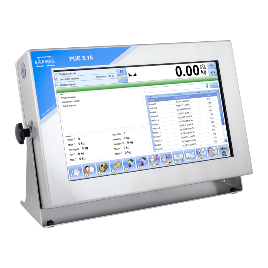
- Page 1 PUE 5 WEIGHING INDICATOR USER MANUAL ITKU-84-04-04-24-EN...
- Page 2 APRIL 2024...
- Page 3 PRECAUTIONS Prior to installation, use or maintenance activities, carefully read this user manual. Use the PUE 5 Indicator only as intended. Prior to the first use, carefully read this user manual. Use the device only as intended. Protect the indicator against considerable temperature variation, solar and UV radiation, substances causing chemical reactions.
-
Page 4: Table Of Contents
4.5. Technical Specifications ..........................11 5. INDICATOR INSTALLATION .......................... 12 5.1. Unpacking and Installation ........................12 5.2. Start-Up ..............................12 6. „PUE 5 CORE” SOFTWARE ........................... 12 6.1. Program Start-up ............................13 6.2. Main Window ............................. 13 6.3. Navigation in the Menu ..........................14 6.3.1. -
Page 5: Intended Use
PUE 5 indicator is a genuine device that consists of two units: the computer and the weighing module, placed in one housing. Both of these units are connected via an internal interface. -
Page 6: Maintenance
3. MAINTENANCE 3.1. Cleaning Stainless Steel Components Avoid using cleansers containing any corrosive chemicals, e.g. bleach (with chlorine). Do not use cleansers containing abrasive substances. Always remove the dirt using microfiber cloth to avoid damage of protective coating. Daily cleaning routine (removal of small stains): 1. - Page 7 PUE 5.15 indicator dimensions PUE 5.19 indicator dimensions...
-
Page 8: Connectors
4.2. Connectors Back PUE 5.15, PUE 5.19 board view Cable glands (x4pcs.) for load cell cable USB M12 4P connector RS232 (2) connector Plug (optionally 4IN, RS232 (1), RS485) Plug (optionally RS232 (3)) Ethernet (2) RJ45 connector USB panel connector... -
Page 9: Connectors Topology
USB panel USB A Standard USB A 4.4. Inputs / Outputs Optional design The PUE 5 indicator is optionally equipped with 4 optoisolated inputs and 4 semiconductor outputs (solid-state relays). 4.4.1. Connectors topology Pin1 – OUT1 Pin2 – OUT2 Pin3 – OUT3 Pin4 –... -
Page 10: Technical Specifications
4.4.2. Technical Specifications Output parameters Output quantity Output type Solid-state relay Cable cross-section 0.14 - 0.5 mm Maximum output current 0.5 A DC Maximum output voltage 30 VDC, AC Input parameters Input quantity Input type Optoisolated Cable cross-section 0.14 - 0.5 mm Voltage range 5 - 24 VDC 4.4.3. -
Page 11: Technical Specifications
4.5. Technical Specifications PUE 5.15 PUE 5.19 Housing stainless steel IP rating IP67 LCD 15,6’’ (1366x768) LCD 19’’ (1280x1024) Display Touch screen 100 ÷ 240VAC 50 ÷ 60Hz Power supply Maximum power consumption 0 ÷ 40C Operation temperature -20C ÷ 60C Storage temperature Max. -
Page 12: Indicator Installation
After completing the startup procedure, the device is ready for operation. 6. „PUE 5 CORE” SOFTWARE ”PUE 5 Core” is a program designed to enable control of MW-04 mass converter. The program allows you to calibrate the mass converter, read mass,... -
Page 13: Program Start-Up
6.1. Program Start-up The program can be launched using the <PUE 5 Core> shortcut on the desktop. After starting the program, the main program window will be displayed. 6.2. Main Window The home page can be divided into 5 fields: ... -
Page 14: Navigation In The Menu
The on-screen functional buttons are showed below: At the bottom of the screen you can see permanent functional buttons: 6.3. Navigation in the Menu Navigation in the menu is intuitive and user-friendly. Thanks to the touch screen display, it is very easy to use the program. Press the screen button or field in the screen to activate the assigned operate or function. -
Page 15: Installer Instruction
Press in the lower bar to return to home page immediately. 7. INSTALLER INSTRUCTION The PUE 5 indicator can be a base component of a load cell scale. 7.1. MW-04 Mass Converter MW-04 Mass Converter MW-04 Mass Converter (334Rxxxx) functions as a base component comprising A/D converter boards and 4IN/4OUT board. -
Page 16: A/D Converter
7.3.1. Connection of the 6-wire Load Cell Connection for load cells featuring 6-lead cable shall be carried out in accordance with diagram presented in figure below: Connection of the 6-wire Load Cell Radwag A/C transducer board Signals from load cell NOTES SHIELD Read point 7.1.3... -
Page 17: Connection Of The 4-Wire Load Cell
7.3.2. Connection of the 4-wire Load Cell Connection for load cells featuring 4-lead cable shall be carried out in accordance with diagram presented in figure below: Connection of the 4-wire load cell Radwag A/C transducer board Signals from load cell NOTES SHIELD Read point 7.1.3... -
Page 18: Factory Parameters
Press ON/OFF switch to power the indicator, the switch is to be found at the back of the housing, wait for the operating system to be loaded. After completing the startup procedure, run the "PUE 5 Core" program using the <PUE 5 Core> shortcut on the desktop. -
Page 19: List Of Global Parameters
Quantity stored Number of stored weighing records. weighing records For the setting: <Disabled (Radwag)>, Disabled (Radwag) when the program is being launched, Empty (white) Radwag logo is displayed. For the setting: VWR Baykon <Empty (white)>, during start-up, Customer BOECO Germany... -
Page 20: List Of Factory Parameters
Parameter Menu with import, export and backup management copy settings. Importing settings from pendrive memory Import into scale. Export Exporting settings to pendrive memory. Menu with backup copy load/record Backup copy functions of global and factory parameters. Set default Restoring default settings. Advanced settings Menu with advanced settings. - Page 21 0, 0.2, 0.4, 0.6, Stability time 0.8, 1, 2, 3, 4, 5, Stability time in [s]. 10, 15, 20. Start mass control: 0 – off, 1 - range: -5% to +15% of start mass, Start mass control 0, 1, 2 2 - range 20% of start mass.
- Page 22 Import of platform 1 parameter settings Import from pendrive mass memory to the scale. Export of platform 1 parameter settings Export to pendrive mass storage. Communication parameters MW-04: indicator with MW-04 mass Communication converter. Address Address of the MW-04 mass converter. 1200 ÷...
-
Page 23: Factory Adjustment
8.4. Factory Adjustment 8.4.1. External Factory Adjustment Enter <Factory> menu and select platform number. Go to <Adjustment> submenu and enter <Adjustment> function. The message: <Adjustment: Unload the weighing pan> will be displayed. Unload weighing pan and press to confirm the message. -
Page 24: Linearity
Determination of factory start mass of the additional platform is analogical to the above-stated description. 8.5. Linearity 8.5.1. Linearity Determination Determining mass for each step of the linearity and corrections via scale software. Procedure: Enter <Factory> menu and select platform number. ... -
Page 25: Corrections
It allows proper adjustment of the scale away from the further use spot. The gravitational correction must be entered on the basis of tables provided by „RADWAG Wagi Elektroniczne” or through calculation as per the following equation: Gcor ... -
Page 26: Diagrams Of Connection Cables
The permissible range, approved by the program, of correction values is as follows: 0,90000 ÷ 1,99999. If the scale is adjusted in the use area, <Gcor> parameter must be set as 1.00000. In case the scale is adjusted away from the further use spot, always enter the gravitational correction. - Page 27 Indicator - printer cable (ZEBRA) USB adapter cable Indicator – barcode scanner cable (LS2208)
-
Page 28: Error Messages
„Scale-Ethernet” cable standard network cable terminated with RJ45 connectors on both ends. 10. ERROR MESSAGES...
Need help?
Do you have a question about the PUE 5 and is the answer not in the manual?
Questions and answers