Table of Contents
Advertisement
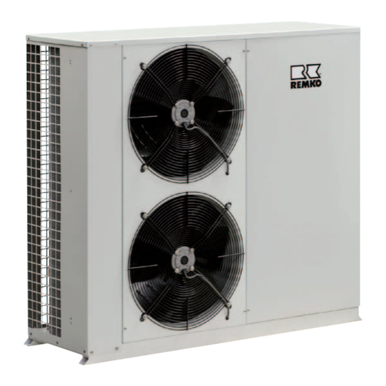
REMKO KWL
KWL 130, KWL 160, KWL 180 (INOX), KWL 220 (INOX),
KWL 270 (INOX), KWL 320 (INOX), KWL 370 (INOX)
KWL 130 H, KWL 160 H, KWL 180 H (INOX),
KWL 220 H (INOX), KWL 270 H (INOX), KWL 320 H (INOX),
KWL 370 H (INOX)
Air-cooled Chiller and
Air-cooled Chiller with Heat Pump function
Operation · Technology · Spare parts
Edition GB – B05
Advertisement
Table of Contents

Summarization of Contents
Safety Notes
Environmental Protection and Recycling
Responsible disposal of packaging and equipment.
Disposal of Equipment and Components
Guidelines for proper disposal of recyclable materials.
Operation
Methods of Operation
Overview of unit control and operating modes.
Adaptive Cooling and Heating Function
Programming Target Values
How to input target values for cooling and heating modes.
Querying Unit Statuses
View adaptive target values and component operating times.
Querying Fault Reports
Fault Reset and Record Access
Procedures for resetting faults and accessing fault history.
Fault Acknowledgement
Process for acknowledging and handling faults.
Controller Operating Structure and Menus
Display Navigation and Value Views
Navigating displays for target and current values.
Menu Access and Parameter Levels
Accessing menus and parameter settings.
Care and Maintenance
Maintenance Recommendations
Scheduled maintenance and service advice.
Shut-down Procedures
Temporary and Permanent Shut-down
Steps for short-term and long-term unit shutdown.
Troubleshooting and Customer Service
Malfunctions and Their Solutions
Identifying and resolving unit faults with causes and remedies.
Fault Indication by Code
Interpretation of fault codes for diagnosis.
Installation Instructions for Qualified Personnel
Wall Openings, Material & Site Selection
Preparing openings, materials, and choosing the installation location.
Environmental Factors and Indoor Installation
Considerations for site conditions and indoor placement.
Minimum Clearances
Required spacing around the unit for proper operation and maintenance.
Installation Procedures
Pallet Separation and Unit Layout
Steps to prepare and position the unit.
Unit Installation and Weight Loads
Attaching the unit and understanding weight distribution.
Medium Piping Connection
System Components and Pipe Routing
Overview of necessary components and piping guidelines.
Medium Flow and System Volume
Flow Limits, Volume Requirements, and Frost Protection
Ensuring correct medium flow, volume, and using glycol.
System Components and Settings
Pressure Gauges, Valves, and Accessories
Installation of measurement devices and balancing valves.
Antifreeze Protection Configuration
Antifreeze Parameters and Glycol Settings
Adjusting settings for antifreeze protection with glycol.
System Components: Expansion Vessels, Valves
Notes on expansion vessels, safety valves, shut-off and bleeding valves.
Condensate Management
Fill, Drain, Dirt Traps, and Reservoirs
Connecting for draining, installing dirt traps, and managing reservoirs.
Condensate Drainage and Leakage Discharge
Ensuring proper condensate flow and secure discharge.
Electrical Connection
Power Supply and Terminal Connections
Connecting the unit to the power supply and terminal details.
External Enabling and Operating Mode Control
Using external contacts for unit operation and standby.
System Control and Accessories
External Controls and Fault Signals
Using external contacts for mode control and fault reporting.
Accessory Functions and Configuration
Notes on winter pressure controllers, crankcase heaters, remote controls.
Electrical Components and Safety Equipment
Pressure Switches and Thermal Contacts
HP/LP switches, differential pressure switch, thermal contacts.
Control Relays, Sensors, and Fan Control
Phase sequence relay, fan control, medium sensors.
Electrical Circuit Diagrams
KWL 130(H) - 160(H) Schematics
Wiring diagrams for KWL 130/160 models.
KWL 180(H) - 320(H) Schematics
Wiring diagrams for KWL 180/320 models.
KWL 370 (H) Schematics
Wiring diagrams for KWL 370 models.
Before Commissioning
System Filling and Medium Preparation
Steps for filling the system and preparing the medium.
Pressure Settings and System Bleeding
Adjusting preliminary pressure and bleeding air.
Commissioning
Working Tests for Cooling and Heating Modes
Procedures for testing the unit in cooling and heating modes.
Final Tasks After Commissioning
Steps to complete after testing, including reassembly.
Characteristic Curves
Pressure Loss and Equipment Pressure Curves
Graphs illustrating pressure loss and equipment pressure.
Technical Data - Cooling and Heating
Cooling and Heating Capacity Performance
Tables detailing cooling and heating output based on conditions.
Sound Pressure Levels
Measurements of sound pressure levels for different models and frequencies.
Technical Data - General Specifications
Operating Modes and Cooling Performance
Details on operating modes, cooling capacity, and efficiency.
Electrical and Medium Specifications
Power consumption, current, flow volumes, and pressures.
Dimensions, Weight, and Serial Numbers
Physical size, weight, and identification data.


Need help?
Do you have a question about the KWL 180 and is the answer not in the manual?
Questions and answers