
Subscribe to Our Youtube Channel
Related Manuals for Carrier AquaForce PUREtec 30XAV-ZE 401


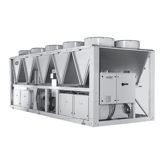
Summary of Contents for Carrier AquaForce PUREtec 30XAV-ZE 401
- Page 1 InsTallaTIon, oPEraTIon and MaInTEnancE InsTrUcTIons Variable-Speed Air-Cooled Screw Chillers AquaForce PUREtec with R1234ze (E) 30XAV-ZE 401-901 nominal cooling capacity : 400-900 kW 50 hz Original document...
-
Page 2: Table Of Contents
Contents 1 - IntRoDUCtIon ..................................4 Installation safety considerations ............................4 1.1 - 1.2 - Equipment and components under pressure ........................5 1.3 - Maintenance safety considerations ............................5 1.4 - Repair safety considerations ..............................8 2 - PRelImInaRy CheCks ..............................10 2.1 - Check equipment received .............................. - Page 3 11.8 - Compressor maintenance ..............................38 11.9 - Variable frequency drive maintenance ..........................38 12 - CheCklIst to Be maDe By the InstalleR BefoRe CallIng CaRRIeR seRVICe CommIssIonIng UnIt ..............................39 the images shown on the cover page and in this document are for illustrative purposes only and are not contractual.
-
Page 4: Introduction
Customer shall obtain approval from the local building authorities. Carrier also provides additional guidelines Prior to the initial start-up of the 30XAV-ZE units, the for the safe use of R1234ze(E) refrigerant that should be... -
Page 5: Equipment And Components Under Pressure
The units can also be lifted with slings, using only the The calibration of a valve that has leaked is generally designated lifting points marked on the unit. lower than its original calibration. The new calibration may affect the operating range. To avoid a nuisance tripping or Use slings with the correct capacity, and always follow leaks, replace or re-calibrate the valve. - Page 6 Before any intervention, Carrier mentions here only the principle of a test without verify that there is no voltage present at any accessible removing the pressure switch: conducting parts of the power circuit.
- Page 7 At least once a year, visually inspect the protection The table below shows this frequency, as originally devices (valves, pressure switches). published in the regulation. Check whether an inspection frequency is also set by other regulations or standards applicable to your system (e.g. EN 378, ISO5149, etc.). If the machine operates in a corrosive environment, inspect the protection devices more frequently.
-
Page 8: Repair Safety Considerations
If a leak occurs or if the refrigerant becomes contaminated (e.g. by a short circuit in a motor) remove the complete Consult Carrier Service for this type of test. Carrier charge using a recovery unit and store the refrigerant in mentions here only the principle of a test without mobile containers. - Page 9 Do not siphon refrigerant. When the refrigerant circuit is opened for repair, it is mandatory to plug all openings of the circuit if the repair Avoid spilling liquid refrigerant on skin or splashing it into exceeds 30 minutes; this is to avoid moisture absorbed in the eyes.
-
Page 10: Preliminary Checks
2 - PrElIMInary chEcks The support points under the chassis must have at least the size of the chassis opening at the lifting point (minimum 220 2.1 - check equipment received x 180 mm) in order to prevent a deformation of the chassis. •... -
Page 11: Actual Start-Up
• Check the protection of moving parts. • Verify the accessibility for maintenance or repair and NOTE: If the Carrier instructions (power and water to check the piping. connections and installation) are not observed, the • Verify the status of the valves. -
Page 12: Dimensions, Clearances
3 - dIMEnsIons, clEarancEs 3.1 - 30XaV-ZE 401-501 without hydronic kit 3.2 - 30XaV-ZE 401-501 with hydronic kit INLET PUMP TYPE - UNIT POMPE DOUBLE HP - XAVZE0401 / 0501 674 POMPE DOUBLE BP - XAVZE0401 / 0501 714 POMPE SIMPLE HP - XAVZE0401 / 0501 POMPE SIMPLE BP - XAVZE0401 / 0501 OUTLET PUMP TYPE - UNIT... -
Page 13: 30Xav-Ze 551
3.3 - 30XaV-ZE 551 3.4 - 30XaV-ZE 651 legend: NOTES: All dimensions are given in mm. • Drawings are not contractually binding. Required clearances for maintenance (see note) • Before designing an installation, consult the certified dimensional drawings, available on request. Recommended space for evaporator tube removal •... -
Page 14: 30Xav-Ze 701
3.5 - 30XaV-ZE 701 3.6 - 30XaV-ZE 851 legend: NOTES: All dimensions are given in mm. • Drawings are not contractually binding. Required clearances for maintenance (see note) • Before designing an installation, consult the certified dimensional drawings, available on request. Recommended space for evaporator tube removal •... -
Page 15: 30Xav-Ze 901
If h < H (2.3 m), minimum S = 3 m recycling of warm air from one unit to another. If h > H or S < 3 m, contact your Carrier distributor to evaluate the various possible arrangements. In certain 1.5 m... -
Page 16: Physical And Electrical Data For 30Xav-Ze Units
4 - PhysICal aND eleCTRICal DaTa fOR 30XaV-Ze UNITs 4.1 - Physical data 30XaV-ZE 30XaV-ZE sound levels standard unit Sound power level*** dB(A) Sound pressure level at 10 m**** dB(A) standard unit + option 279* Sound power level*** dB(A) Sound pressure level at 10 m**** dB(A) standard unit + option 257* Sound power level***... -
Page 17: Electrical Data 30Xav-Ze
4.2 - Electrical data 30XaV-ZE 30XaV-ZE Power circuit Voltage range V-ph-Hz 400-3-50±10% control circuit supply 24 V via internal transformer start-up current* Not Applicable (less than the operating current) Power factor** Maximum*** 0.90-0.92 Cosine phi > 0.98 Total harmonic distortion*** 35-45 Maximum unit power input**** Circuit 1... -
Page 18: Compressor Electrical Data 30Xav-Ze
• The Carrier 30XAV-ZE units are designed and built to ensure conformance • Leakage currents: If protection by monitoring the leakage currents is with these codes. The recommendations of European standard EN 60204-1... -
Page 19: Electrical Connection
The following is only to be used as a guide- 5.1 - Power supply line, and does not make Carrier in any way liable. After wire sizing has been completed, using the certified The power supply must conform to the specification on the dimensional drawing, the installer must ensure easy chiller nameplate. -
Page 20: Field Control Wiring
table of minimum and maximum wire sections (per phase) for connection to 30XaV-Ze units 30XaV-ZE- Max. calculation favourable case: calculation unfavourable case: connectable - suspended aerial lines (standardised routing no. 17) - conductors in conduits or multi-conductor cables in closed section* - XlPE insulated cable conduit (standardised routing no. -
Page 21: Application Data
Evaporator ∆T = 5K the next page. If the system fl ow exceeds the maximum These ranges are given by way of indication. Verify the operating range from the Carrier electronic catalogue. value, it can be bypassed as shown in the diagram. -
Page 22: Variable Flow Evaporator
6.4 - Variable flow evaporator Connection to a buffer tank Variable evaporator flow can be used as standard with 30XAV-ZE chillers. The chillers maintain a constant leaving water temperature under all flow conditions. For this to happen, the flow rate must be higher than the minimum flow given in the table of permissible flow rates good Mauvais... -
Page 23: Water Connections
In case additives or other fluids than those recommen- Electric conductivity 10-600μS/cm. ded by Carrier are used, ensure that the fluids are not 10. pH: Ideal case of neutral pH at 20-25 °C considered as a gas, and that they belong to class 2, as (7.5 <... -
Page 24: Victaulic Water Connections
7.2 - Victaulic water connections 7.2.1 - hydronic connections Inlet/outlet diameters 30XaV-ZE standard Nominal Diameter Actual External Diameter 141.3 168.3 168.3 168.3 168.3 219.1 219.1 options 100c Nominal Diameter Actual External Diameter 168.3 168.3 168.3 168.3 168.3 219.1 219.1 options 116 Nominal Diameter Actual External Diameter 141.3... - Page 25 7.2.2 - Piping limitations Depending on the unit size and options, the space between water box connections and the nearest component can Clearance vary. This results in piping limitations. In the case of straight pipes, the space remaining available for pipe insulation are listed in the table below.
-
Page 26: Flow Detection
7.5.2 - optional evaporator freeze protection (30XaV-Ze) Failure to follow this instruction will void the Carrier guarantee. In cases where it is not possible to apply the recommenda- tions in paragraph 7.5.1, the units can be equipped with... -
Page 27: Operation Of Two Units In Master/Slave Mode (Option 58)
30XaV-Ze with configuration: leaving water control 7.7 - operation of two units in master/slave mode (option 58) As standard, the control of a master/slave assembly is from the entering water temperature and does not require any additional sensors (standard configuration). It can also be controlled from the leaving water temperature, in this case two additional sensors must be added on the common piping. -
Page 28: Unit With Hydronic Kit
8 - UNIT WITh hyDRONIC KIT 8.1 - available static pressure for the system Data applicable for fresh water, 20°C - In case of use of the glycol, the maximum water flow is reduced - Glycol percentage is limited to 40% - For ambiant temperature over 40°C, maximum water flow is limited low pressure pumps (options 116T/116U) 501 simple... -
Page 29: Npsh (Net Positive Suction Head) Required ; Hydronic Module Option
These data are given for indicative purpose to user and 30XAV-ZE control manual). may vary depending on hydronic circuit fouling and proper operation of the pump. Carrier does not undertake Fluid pressure is measured by pressure sensors fitted at the accuracy of this information. -
Page 30: Major System Components And Operation Data
Must follow local regulations and be made by qualified following lubricants: operators and in accordance with qualified procedures, • Carrier material specification PP47-38 this include changing the heat exchanger tubes. • Must be made in accordance with the instructions of ATTENTION: Too much oil in the circuit can cause a the original manufacturer. -
Page 31: High-Pressure Safety Switch
This is also the case for together at the same rotational speed. The rotational speed the products originally supplied by Carrier. at full load or partial load of each circuit is controlled by an algorithm that continuously optimises the condensing temperature to obtain the best energy efficiency (EER) 9.7.7 - oil separator... -
Page 32: Electronic Expansion Valve (Exv)
According to the Regulation No. 327/2011 implementing directive 2009/125/EC with regard to ecodesign requirements for fans driven by motors with an electric input power between 125 W and 500 kilowatts. Product 30XaV-ZE Global fan efficiency Measurement category Efficiency category Static Energy efficiency target N(2015) N(2015) 40 Efficiency level at the optimum efficiency point... -
Page 33: Service Valve (Option 92)
If there (within the acceptable range) is managed through RS485 is a pressure difference, leak-tightness at the valve may be communication via LEN Protocol by the "Carrier lost and the valve can even fail altogether. Controller". -
Page 34: Options
10 - oPTIons options description avantages Utilisation IP54 control box Increased leak tightness of control boxes Protects the inside of the electrical box from dusts and sand. 401-901 In general this option is recommended for installations in polluted environments Grilles and enclosure panels Metal grilles on the 4 unit sides, plus side Improves aesthetics, protection against intrusion to the unit 401-901... - Page 35 298 while all of them must be equipped with option 149 NOTE 3: If the Carrier PlantCTRL™ is on site, ® option 298 shall be integrated in the Carrier ® PlantCTRL™ while option 149 is still mandatory for each single unit. Variable Water Flow control...
-
Page 36: Standard Maintenance
In these cases, the following maintenance operations are recommended. A Carrier Service maintenance contract is the best way to ensure the maximum operating life for your equipment Carry out all level 1 operations, then: and, through the expertise of Carrier technicians, provides •... -
Page 37: Tightening Torques For The Main Electrical Connections
To reduce waste, the refrigerant and the oil must be 11.4.2 - Connection precautions for the compressor power terminals transferred in accordance with applicable regulations, using methods that limit refrigerant leaks and pressure These precautions must be applied during an intervention drops and with materials that are suitable for the products. -
Page 38: Evaporator Maintenance
Products qualified as suitable for cleaning untreated Correct compressor rotation is one of the most critical MCHE coils are available from the Carrier spare parts application considerations. Reverse rotation, even for a network. After cleaning, rinsing of the coil is mandatory very short duration, damages the compressor. -
Page 39: Checklist To Be Made By The Installer Before Calling Carrier Service Commissioning Unit
12 - CheCKlIsT TO Be MaDe By The INsTalleR BefORe CallINg CaRRIeR seRVICe COMMIssIONINg UnIT Preliminary information Job name: ......................................Location: ........................................ Installing contractor: .................................... Distributor: ......................................equipement Model 30XAV-ZE: ....................................Compressors Circuit A Circuit B Model # Model #... - Page 40 WARNING: Operation of the chiller with an improper supply voltage or excessive phase imbalance constitutes abuse which will invalidate the Carrier warranty. If the phase imbalance exceeds 2% for voltage, or 10% for current, immediately contact your local electricity supply at once and ensure that the chiller is not switched on until corrective measures have been taken .
- Page 41 To Start the chiller WARNING: Ensure that all service valves are open, and the pump is running before attempting to start this machine. Once all checks have been made, try to start the unit. The unit starts and runs properly. Temperatures and pressures WARNING: Once the machine has been operating for a while and the temperatures and pressures have stabilised, record the following:...
- Page 44 Order No: 10159, 07.2016 - Supersedes order No: New. Manufacturer: Carrier SCS, Montluel, France. Manufacturer reserves the right to change any product specifications without notice. Printed in the European Union.
Need help?
Do you have a question about the AquaForce PUREtec 30XAV-ZE 401 and is the answer not in the manual?
Questions and answers