
Related Manuals for Carrier AquaForce 30XAV 500


Summary of Contents for Carrier AquaForce 30XAV 500
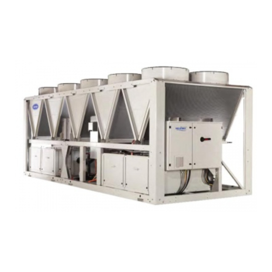
- Page 1 I N S T A L L A T I O N , O P E R A T I O N A N D M A I N T E N A N C E I N S T R U C T I O N S Variable-Speed Air-Cooled Screw Chillers 30XAV 500 - 1150 Nominal cooling capacity : 500 - 1150 kW...
-
Page 2: Table Of Contents
CONTENTS 1 - INTRODUCTION ..................................4 1.1 - Installation safety considerations ............................4 1.2 - Equipment and components under pressure ........................5 1.3 - Maintenance safety considerations ............................5 1.4 - Repair safety considerations ..............................7 2 - PRELIMINARY CHECKS ..............................8 2.1 - Check equipment received .............................. - Page 3 11.8 - Compressor maintenance ..............................37 11.9 - Variable frequency drive maintenance ..........................37 12 - CHECKLIST TO BE MADE BY THE INSTALLER BEFORE CALLING CARRIER SERVICE COMMISSIONING UNIT ................................38 The images shown on the cover page and in this document are for illustrative purposes only and are not contractual.
-
Page 4: Introduction
Fire extinguishers appropriate to the system and the company. refrigerant type must be easily accessible. Carrier strongly recommends employing a specialised All factory -installed relief valves are lead-sealed to prevent company to unload the machine. any calibration change. The external relief valves must... -
Page 5: Equipment And Components Under Pressure
1.3 - Maintenance safety considerations Ensure good ventilation, as accumulation of refrigerant in an enclosed space can displace oxygen and cause Carrier recommends the following drafting for a logbook asphyxiation or explosions. (the table below should not be considered as reference and... - Page 6 Ensure that the refrigerant is never released to the - Recommissioning of the equipment. atmosphere during installation, maintenance or Consult Carrier Service for this type of test. Carrier mentions equipment disposal. here only the principle of a test without removing the...
-
Page 7: Repair Safety Considerations
1.4 - Repair safety considerations Avoid spilling liquid refrigerant on skin or splashing it into the eyes. Use safety goggles and safety gloves. Wash any spills All installed parts must be maintained by the personnel in from the skin with soap and water. If liquid refrigerant enters charge, in order to avoid deterioration and injury. -
Page 8: Preliminary Checks
ATTENTION: No part of the unit must be used as a walk- - Voltage, frequency, number of phases way, rack or support. Periodically check and repair or if - Maximum current drawn necessary replace any component or piping that shows signs - Maximum power input of damage. -
Page 9: Actual Start-Up
• Compare the complete installation with the refrigeration system and power circuit diagrams. NOTE: If the Carrier instructions (power and water • Check that all components comply with the design connections and installation) are not observed, the Carrier specifications. -
Page 10: Dimensions, Clearances
3 - DIMENSIONS, CLEARANCES 3.1 - 30XAV 500-600 without hydronic kit 3.2 - 30XAV 500-600 with hydronic kit NOTES: Legend: All dimensions are given in mm. • Drawings are not contractually binding. Required clearances for maintenance (see note) • Before designing an installation, consult the certified dimensional drawings, available on request. -
Page 11: 30Xav 700
3.3 - 30XAV 700 3.4 - 30XAV 800 NOTES: Legend: All dimensions are given in mm. • Drawings are not contractually binding. Required clearances for maintenance (see note) • Before designing an installation, consult the certified dimensional drawings, available on request. Recommended space for evaporator tube removal • For the positioning of the fixing points, weight Water inlet for standard unit distribution and centre of gravity coordinates please For options 5, 6, 100A, 100C, 107 refer to the certified drawing. -
Page 12: 30Xav 950
3.5 - 30XAV 950 3.6 - 30XAV 1050 NOTES: Legend: All dimensions are given in mm. • Drawings are not contractually binding. Required clearances for maintenance (see note) • Before designing an installation, consult the certified dimensional drawings, available on request. Recommended space for evaporator tube removal • For the positioning of the fixing points, weight Water inlet for standard unit distribution and centre of gravity coordinates please For options 5, 6, 100A, 100C, 107 refer to the certified drawing. -
Page 13: 30Xav 1150
If h < H (2.3 m), minimum S = 3 m of warm air from one unit to another. If h > H or S < 3 m, contact your Carrier distributor to evaluate the various possible arrangements. In certain 1.5 m... -
Page 14: Physical And Electrical Data For 30Xav Units
4 - PHYSICAL AND ELECTRICAL DATA FOR 30XAV UNITS 4.1 - Physical data 30XAV 30XAV 1050 1150 Sound levels Standard unit Sound power level*** dB(A) Sound pressure level at 10 m**** dB(A) Standard unit + option 279* Sound power level*** dB(A) Sound pressure level at 10 m**** dB(A) -
Page 15: Electrical Data 30Xav
4.2 - Electrical data 30XAV 30XAV 1050 1150 Power circuit Voltage range V-ph-Hz 400-3- 50±10% Control circuit supply 24 V via internal transformer Start-up Current* Not Applicable (less than the operating current) Power factor** Maximum*** 0.91-0.93 Cosine phi > 0.98 Total harmonic distortion*** 35-45 Maximum unit power input**** Circuit 1 † Circuit 2 †... -
Page 16: Electrical Data, Optional Hydronic Module
I. Altitudes above sea level < 1000**** II. Ambient air temperature °C < 40* (up to 50°C with reduced water flow) III. Maximum air temperature °C Please refer to the operating conditions given in this manual or in the specific conditions in the Carrier selection programs. IV. Potentially explosive atmosphere Non ATEX environment For of high pressure pump motors (options 116B & 116C) N°* Description*** Units 30XA Nominal efficiency at full load and nominal voltage... -
Page 17: Compressor Electrical Data 30Xav
NOTE: If particular aspects of an actual installation do not conform to the equipment**. conditions described above, or if there are other conditions which should be • Appendix B of standard EN 60204-1 specifies the electrical characteristics used for the considered, always contact your local Carrier representative. operation of the machines. Those specified below are applied to 30XAV units in addition to other information given in this document: Depending on the size or options selected for the machine Physical environment***; The classification of the environment is specified in standard... -
Page 18: Electrical Connection
The following is only to be used as a guide-line, 5.1 - Power supply and does not make Carrier in any way liable. After wire sizing has been completed, using the certified dimensional drawing, The power supply must conform to the specification on the the installer must ensure easy connection and define any chiller nameplate. -
Page 19: Field Control Wiring
Table of minimum and maximum wire sections (per phase) for connection to 30XAV units 30XAV Max. Calculation favourable case: Calculation unfavourable case: connectable - Suspended aerial lines (standardised routing No. 17) - Conductors in conduits or multi-conductor cables in closed section* - XLPE insulated cable conduit (standardised routing No. -
Page 20: Application Data
The maximum chilled water flow is shown in the table on the Full load next page. If the system flow exceeds the maximum value, it Note: can be bypassed as shown in the diagram. Evaporator ∆T = 5K These ranges are given by way of indication. Verify the operating range from the Carrier electronic catalogue. For maximum chilled water flow rate Legend Operating range, standard unit 30XAV Below 0 °C air temperature the unit must either be equipped with the evaporator freeze protection option 41A, or the water loop must be protected against freeze by using a freeze protection solution (by the installer). -
Page 21: Variable Flow Evaporator
6.4 - Variable flow evaporator Connection to a buffer tank Variable evaporator flow can be used as standard with 30XAV chillers. The chillers maintain a constant leaving water temperature under all flow conditions. For this to happen, the flow rate must be higher than the minimum flow given Good in the table of permissible flow rates and must not vary by more than 10% per minute. -
Page 22: Water Connections
Electric conductivity 10-600μS/cm. by Carrier are used, ensure that the fluids are not 10. p H : I d e a l c a s e o f n e u t r a l p H a t 2 0 - 2 5 ° C considered as a gas, and that they belong to class 2, as (7.5 <... -
Page 23: Victaulic Water Connections
7.2 - Victaulic water connections 7.2.1 - Hydronic connections Inlet/outlet diameters 30XAV 1050 1150 Standard Nominal Diameter Actual External Diameter 141.3 168.3 168.3 168.3 168.3 219.1 219.1 Options 100C Nominal Diameter Actual External Diameter 168.3 168.3 168.3 168.3 168.3 219.1 219.1 Options 116 Nominal Diameter Actual External Diameter 141.3 141.3 The hydronic module options are compatible only with closed heat exchange fluid loops. - Page 24 7.2.2 - Piping limitations Depending on the unit size and options, the space between water box connections and the nearest component can vary. Clearance This results in piping limitations. In the case of straight pipes, the space remaining available for pipe insulation are listed in the table below.
-
Page 25: Flow Detection
Failure with hydronic kit). The antifreeze solution and heaters can to follow this instruction will void the Carrier guarantee. be combined. The water flow switch is installed on the evaporator water... -
Page 26: Operation Of Two Units In Master/Slave Mode (Option 58)
7.7 - Operation of two units in master/slave mode 30XAV with configuration: Leaving water control (option 58) As standard, the control of a master/slave assembly is from the entering water temperature and does not require any additional sensors (standard configuration). It can also be controlled from the leaving water temperature, in this case two additional sensors must be added on the common piping. -
Page 27: Unit With Hydronic Kit
8 - UNIT WITH HYDRONIC KIT 8.1 - Available static pressure for the system Data applicable for fresh water, 20°C - In case of use of the glycol, the maximum water flow is reduced - Glycol percentage is limited to 40% - For ambiant temperature over 40°C, maximum water flow is limited Low pressure pumps (options 116T/116U) Low pressure pumps (options 116T/116U) -
Page 28: Npsh (Net Positive Suction Head) Required ; Hydronic Module Option
Fluid pressure is measured by pressure sensors fitted at pump operation of the pump. Carrier does not undertake the inlet and unit outlet. The system calculates the flow rate accuracy of this information. -
Page 29: Major System Components And Operation Data
• Must follow local regulations and be made by qualified • Castrol Icematic SW220 (Carrier specification PP47-32) operators and in accordance with qualified procedures, • Lubrizol Emkarate RL220H (Carrier specification this include changing the heat exchanger tubes. -
Page 30: High-Pressure Safety Switch
This is also the case for or partial load of each circuit is controlled by an algorithm the products originally supplied by Carrier. that continuously optimises the condensing temperature to obtain the best energy efficiency (EER) whatever the 9.7.7 - Oil separator... -
Page 31: Electronic Expansion Valve (Exv)
According to the Regulation No. 327/2011 implementing directive 2009/125/EC with regard to ecodesign requirements for fans driven by motors with an electric input power between 125 W and 500 kilowatts. Product 30XAV Global fan efficiency Measurement category Efficiency category Static Energy efficiency target N(2015) N(2015) 40 Efficiency level at the optimum efficiency point 45.7 Variable frequency drive... -
Page 32: Service Valve (Option 92)
The compressor start-up/stop and the frequency setpoint and the valve can even fail altogether. (within the acceptable range) is managed through RS485 communication via LEN Protocol by the "Carrier Controller". Equal pressure One of the other features of the "variable frequency drive"... -
Page 33: Options
10 - OPTIONS Options Description Avantages Utilisation IP54 control box Increased leak tightness of control boxes Protects the inside of the electrical box from dusts and sand. 500-1150 In general this option is recommended for installations in polluted environments Grilles and enclosure panels Metal grilles on the 4 unit sides, plus side Improves aesthetics, protection against intrusion to the unit 500-1150 enclosure panels at each end of the coil interior, coil and piping protection against impacts. Enclosure panels Side enclosure panels at each end of the coil Improves aesthetics, coil and piping protection against 500-1150... - Page 34 QM295 New software algorithms to allow quick restart Full capacity recovery in less than 5 minutes after power 500-1150 and fast loading while preserving unit-reliability failure. Matches requirements of typical critical missions applications Carrier Connect link (BSS 3G router board Enabler for Carrier Connect service offer 500-1150 regions only) NOTE 1: require option 149 NOTE 2: when more than one machine is...
-
Page 35: Standard Maintenance
In these cases, the following maintenance operations are A Carrier Service maintenance contract is the best way to recommended. ensure the maximum operating life for your equipment and, Carry out all level 1 operations, then: through the expertise of Carrier technicians, provides the •... -
Page 36: Tightening Torques For The Main Electrical Connections
To reduce waste, the refrigerant and the oil must be 11.4.2 - Connection precautions for the compressor power transferred in accordance with applicable regulations, using terminals methods that limit refrigerant leaks and pressure drops and These precautions must be applied during an intervention with materials that are suitable for the products. -
Page 37: Evaporator Maintenance
Carrier spare parts network. After cleaning, rinsing of the coil is mandatory (see Carrier The reverse rotation protection scheme must be able to standard RW01--25). The use of any other cleaning product determine the direction of rotation and stop the compressor is strictly prohibited. -
Page 38: Checklist To Be Made By The Installer Before Calling Carrier Service Commissioning Unit
12 - CHECKLIST TO BE MADE BY THE INSTALLER BEFORE CALLING CARRIER SERVICE COMMISSIONING UNIT Preliminary information Job name: ......................................Location: ........................................ Installing contractor: .................................... Distributor: ......................................Equipement Model 30XAV: ....................................... Compressors Circuit A Circuit B Model # Model #... - Page 40 WARNING: Operation of the chiller with an improper supply voltage or excessive phase imbalance constitutes abuse which will invalidate the Carrier warranty. If the phase imbalance exceeds 2% for voltage, or 10% for current, immediately contact your local electricity supply at once and ensure that the chiller is not switched on until corrective measures have been taken .
- Page 41 To Start the chiller WARNING: Ensure that all service valves are open, and the pump is running before attempting to start this machine. Once all checks have been made, try to start the unit. The unit starts and runs properly. Temperatures and pressures WARNING: Once the machine has been operating for a while and the temperatures and pressures have stabilised, record the following:...
- Page 42 Order No: 13552, 12.2016 - Supersedes order No: 13552, 07.2015. Manufacturer: Carrier SCS, Montluel, France. Manufacturer reserves the right to change any product specifications without notice. Printed in the European Union.
Need help?
Do you have a question about the AquaForce 30XAV 500 and is the answer not in the manual?
Questions and answers