
Related Manuals for Sentera Controls DPSA-2


Summary of Contents for Sentera Controls DPSA-2
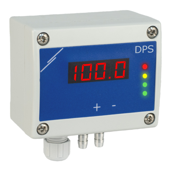
- Page 1 DPSA -2 DIFFERENTIAL PRESSURE CONTROLLER WITH DISPLAY FOR DAMPER ACTUATORS Mounting and operating instructions...
-
Page 2: Table Of Contents
DPSA -2 DIFFERENTIAL PRESSURE CONTROLLER WITH DISPLAY FOR DAMPER ACTUATORS Table of contents SAFETY AND PRECAUTIONS PRODUCT DESCRIPTION ARTICLE CODES INTENDED AREA OF USE TECHNICAL DATA STANDARDS OPERATIONAL DIAGRAM WIRING AND CONNECTIONS MOUNTING INSTRUCTIONS IN STEPS OPERATING INSTRUCTIONS VERIFICATION OF THE INSTALLATION INSTRUCTIONS TRANSPORT AND STORAGE WARRANTY AND RESTRICTIONS MAINTENANCE... -
Page 3: Dpsa -2
DPSA -2 DIFFERENTIAL PRESSURE CONTROLLER WITH DISPLAY FOR DAMPER ACTUATORS SAFETY AND PRECAUTIONS Read all the information, the datasheet, Modbus map, mounting and operating instructions and study the wiring and connection diagram before working with the product. For personal and equipment safety, and for optimum product performance, make sure you entirely understand the contents before installing, using, or maintaining this product. -
Page 4: Product Description
DPSA -2 DIFFERENTIAL PRESSURE CONTROLLER WITH DISPLAY FOR DAMPER ACTUATORS PRODUCT DESCRIPTION The DPSA -2 series are high resolution differential pressure controllers with display. The integrated PI control with anti-windup function offers the possibility to directly control damper actuators. They are equipped with a fully digital state-of-the-art pressure transducer designed for a wide range of applications. -
Page 5: Standards
DPSA -2 DIFFERENTIAL PRESSURE CONTROLLER WITH DISPLAY FOR DAMPER ACTUATORS STANDARDS ■ Low Voltage Directive 2014/34/EC ► EN 60529:1991 Degrees of protection provided by enclosures (IP Code) Amendment AC:1993 to EN 60529 ► EN 60730-1:2011 Automatic electrical controls for household and similar use - Part 1: General requirements ■... -
Page 6: Wiring And Connections
DPSA -2 DIFFERENTIAL PRESSURE CONTROLLER WITH DISPLAY FOR DAMPER ACTUATORS WIRING AND CONNECTIONS Article type DPSAF -2 DPSAG -2 18—34 VDC 18—34 VDC 15—24 VAC ±10% Ground Common ground AC ~ Modbus RTU (RS485), signal A Modbus RTU (RS485), signal /B Analogue / modulating output (0—10 VDC / 0—20 mA / PWM) Ground AO Common ground... - Page 7 DPSA -2 DIFFERENTIAL PRESSURE CONTROLLER WITH DISPLAY FOR DAMPER ACTUATORS Fig. 3 Connections Power supply Modbus RTU G: 15—24 VAC ±10% / 18—34 VDC Analogue / modulating output F: 18—34 VDC 0—10 VDC / 0—20 mA/PWM Connect the nozzles to the duct (see Fig. 4). Depending the application you must use a specific connection set to connect the nozzles of the unit to the duct: To measure differential pressure, use PSET-QF or PSET-PVC set (pressure measurement is the unit default setting);...
- Page 8 DPSA -2 DIFFERENTIAL PRESSURE CONTROLLER WITH DISPLAY FOR DAMPER ACTUATORS For sensor calibration and Modbus registers reset procedures, refer to section NO T E “Operating instructions”. Always calibrate the sensor before initial use. PWM voltage selection: When the internal pull-up resistor (JP1) is connected , the voltage source is set via Modbus holding register 54, i.e.
-
Page 9: Operating Instructions
DPSA -2 DIFFERENTIAL PRESSURE CONTROLLER WITH DISPLAY FOR DAMPER ACTUATORS For the complete Modbus register data, refer to the product Modbus Register NO T E Map, which is a separate document attached to the article code on the website and contains the registers list. Products with earlier firmware versions may not be compatible with this list. - Page 10 DPSA -2 DIFFERENTIAL PRESSURE CONTROLLER WITH DISPLAY FOR DAMPER ACTUATORS Fig. 9 Modbus holding register reset jumper Modbus communication holding registers from 1 to 3 will be reset to the default values. Remove the jumper. Correct reading of air velocity is possible only if it is enabled by holding register ATTENTION 64 (Pitot air velocity) and a transmitter is connected to the appropriate Pitot tube connection set (PSET-PTX-200).
- Page 11 DPSA -2 DIFFERENTIAL PRESSURE CONTROLLER WITH DISPLAY FOR DAMPER ACTUATORS Fig. 11 Out of range indication 11 a Below control range minimum limit 11 b Above control range maximum limit Air volume flow display mode: Air volume flow rate within the range 0—9999 m /h is displayed with a resolution of 1 m /h.
-
Page 12: Verification Of The Installation Instructions
DPSA -2 DIFFERENTIAL PRESSURE CONTROLLER WITH DISPLAY FOR DAMPER ACTUATORS Fig. 14 Sensor element error Sensor failure condition is displayed only if the display is not in OFF mode (enabled NO T E and disabled via holding register 91). LED indications - LED display disabled (See Fig. 15): When the green LED1 is on, the power supply is adequate and Modbus RTU communication is active. -
Page 13: Transport And Storage
DPSA -2 DIFFERENTIAL PRESSURE CONTROLLER WITH DISPLAY FOR DAMPER ACTUATORS Fig. 16 Power / Modbus communication indication ATTENTION The status of the LEDs can be checked only when the unit is energised. Take the relevant safety measures! TRANSPORT AND STORAGE Avoid shocks and extreme conditions;...
Need help?
Do you have a question about the DPSA-2 and is the answer not in the manual?
Questions and answers