Table of Contents
Advertisement
Quick Links
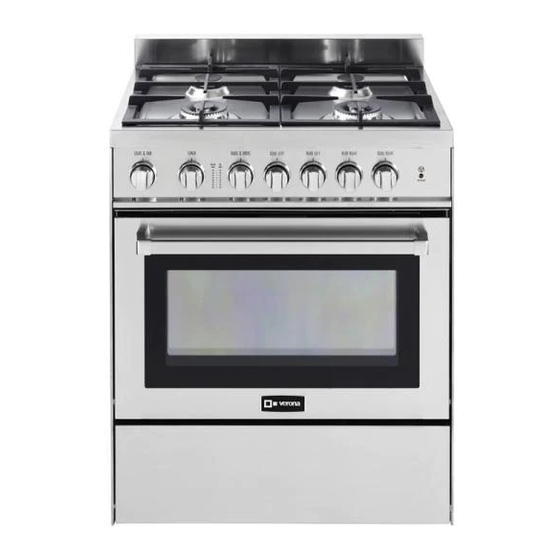
GAS RANGE
for residential use only
VEFSGG 304 ..
Models:
USERS OPERATING INSTRUCTIONS
IMPORTANT - PLEASE READ AND FOLLOW
• Before beginning, please read these instructions completely and carefully.
• Do not remove permanently affixed labels, warnings, or plates from the product. This may
void the warranty.
• Please observe all local and national codes and ordinances.
• Please ensure that this product is properly grounded.
• The electrical plug should always be accessible.
• The installer should leave these instructions with the consumer who should retain
for local inspector's use and for future reference.
Installation must conform with local codes or in the absence of codes, the National Fuel Gas
Code ANSI Z223.1/NFPA 54 - Iatest edition. Electrical installation must be in accordance with
the National Electrical Code, ANSI/NFPA70 - latest edition and/or local codes.
IN CANADA: Installation must be in accordance with the current CAN/CGA-B149.1 National
Gas Installation Code or CAN/CGA-B149.2, Propane Installation Code and/or local codes.
Electrical installation must be in accordance with the current CSA C22.1 Canadian Electrical
Codes Part 1 and/or local codes.
INSTALLATION IN MANUFACTURED (MOBILE) HOME: The installation must conform with
the Manufactured Home Construction and Safety Standard, Title 24 CFR, Part 3280 [formerly
the Federal Standard for Mobile Home Construction and Safety, Title 24, HUD (Part 280)]
or, when such standard is not applicable, the Standard for Manufactured Home Installations,
ANSI/NCSBCS A225.1, or with local codes where applicable.
INSTALLATION IN RECREATIONAL PARK TRAILERS: The installation must conform with
state or other codes or, in the absence of such codes, with the Standard for Recreational Park
Trailers, ANSI A119.5.
Installation of any gas-fired equipment should be made by a licensed plumber. A manual shut-
off valve must be installed in an accessible location in the gas line external to the appliance
for the purpose of turning on or shutting off gas to the appliance (In Massachusetts such shu-
toff devices should be approved by the Board of State Examiners of Plumbers & Gas Fitters).
If an external electrical source is utilized, the appliance, when installed, must be electrically
grounded in accordance with local codes or, in the absence of local codes, with the national
Electrical Code, ANSI/NFPA 70.
Some models are supplied with a protective film on steel and aluminium
parts. This film must be removed before installing/using the appliance.
THIS RANGE IS FOR RESIDENTIAL USE ONLY
R
Advertisement
Table of Contents

Related Manuals for Verona VEFSGG 304 Series


Summary of Contents for Verona VEFSGG 304 Series
- Page 1 GAS RANGE for residential use only VEFSGG 304 .. Models: USERS OPERATING INSTRUCTIONS IMPORTANT - PLEASE READ AND FOLLOW • Before beginning, please read these instructions completely and carefully. • Do not remove permanently affixed labels, warnings, or plates from the product. This may void the warranty. • Please observe all local and national codes and ordinances. • Please ensure that this product is properly grounded. • The electrical plug should always be accessible. • The installer should leave these instructions with the consumer who should retain for local inspector’s use and for future reference.
-
Page 2: What To Do If You Smell Gas
WARNING ! To reduce the risk of tipping the appliance, the appliance must be secured by properly installed anti-tip device packed with the appliance. • ALL RANGES CAN TIP • INJURY TO PERSONS COULD RESULT • INSTALL ANTI-TIP DEVICE PACKED WITH RANGE • SEE INSTALLATION INSTRUCTIONS WARNING ! If the information in this manual is not followed exactly, a fire or explosion may result causing property damage, personal injury, or death. – Do not store or use gasoline or other flammable vapors and liquids in the vicinity of this or any other appliance. - Page 3 Dear Customer, Thank you for having purchased and given your preference to our product. The safety precautions and recommendations reported below are for your own safety and that of others. They will also provide a means by which to make full use of the features offered by your appliance. Please preserve this booklet carefully.
-
Page 4: General Information
USER INSTRUCTIONS GENERAL INFORMATION WARNING!! WARNING!! 1. ELECTRICAL GROUNDING INSTRUCTIONS This appliance shall not be used for space heating. This The range must be electrically grounded in accordance with information is based on safety considerations. local codes or, in the absence of local codes, with the Natio- nal Electrical Code, ANSI/NFPA No. 70-latest edition, in Cana- 2. To eliminate risk of burns or fire by reaching over heated sur- da Canadian Electrical Code. face units, cabinet storage located above the surface units should be avoided. Installation should be made by a Iicensed electrician. FOR PERSONAL SAFETY, THIS APPLIANCE MUST BE PRO- 3. AlI openings in the wall behind the appliance and in the floor PERLY GROUNDED. under the appliance shall be sealed. If an external electrical source is utilized, the installation must be 4. Keep appliance area clear and free from combustible mate- electrically grounded in accordance with local codes or, in the rials, gasoline, and other flammable vapors. -
Page 5: Important Precautions And Recommendations
IMPORTANT PRECAUTIONS AND RECOMMENDATIONS After having unpacked the appliance, check to ensure that it is not damaged. In case of doubt, do not use it and consult your supplier or a professionally qualified technician. Packing elements (i.e. plastic bags, polystyrene foam, nails, packing straps, etc.) should not be left around within easy reach of children, as these may cause serious injuries. The packaging material is recyclable and is marked with the recycling symbol • Do not attempt to modify the technical characteristics of the appliance as this may become dangerous to use. • Do not carry out cleaning or maintenance operations on the appliance without having previously di- sconnected it from the electric power supply. • After use, ensure that the knobs are in position. • Do not allow children or other incapable people to use the appliance without supervision. • During and after use of the range, certain parts will become very hot. Do not touch hot parts. • Keep children away from the range when it is in use. • Some models are supplied with a protective film on steel and aluminium parts. This film must be remo- ved before installing/using the appliance. • Fire risk! Do not store flammable material in the oven and in the storage compartment (accessible through a pivoting panel). • Make sure that electrical cables connecting other appliances in the proximity of the range cannot come into contact with the hob or become entrapped in the oven door. • Do not line the oven walls with aluminium foil. Do not place shelves, broiler pan, pans or other cooking utensils on the base of the oven chamber. • The manufacturer declines all liability for injury to persons or damage to property caused by incorrect or improper use of the appliance. • To avoid any possible hazard, the appliance must be installed by qualified personnel only. Any repairs by unqualified persons may result in electric shock or short circuit. In order to avoid possible injuries to your body or to the appliance, do not attempt any repairs by yourself. Such work should be carried... -
Page 6: Gas Burners
features Fig. 1.1 GAS BURNERS 1. Rear left Semi-rapid burner (SR) - 8000 BTU/hr 2. Rear right Semi-rapid burner (SR) - 8000 BTU/hr 3. Front right Dual burner (D) - 17000 BTU/hr 4. Front left Dual burner (D) - 17000 BTU/hr Note: • The electric gas-lighting device is incorporated into the knobs. • The appliance has a safety valve system fitted. The flow of gas will stop if and when the flame should acciden- tally go out. CAUTION: If the burner is accidentally extinguished, turn the gas off at the control knob and wait at least 1 minute befo- re attempting to relight. CAUTION: Gas appliances produce heat and humidity in the en- vironment in which they are installed. Ensure that the cooking area is well ventilated fol- lowing national/local codes. - Page 7 Fig. 1.2 CONTROLS DESCRIPTION Gas cooking hob controls: Oven controls: 1. Front left burner (4) control knob 5. Oven and broil burner control knob 2. Rear left burner (1) control knob 6. Oven light & fan control knob 3. Rear right burner (2) control knob 7. Cooling fan failure warning light 4. Front right burner (3) control knob 8. 60 minutes alarm control knob COOLING FAN WARNING LIGHT WARNING VERY IMPORTANT NOTICE Operate the cooking hob burners When the cooling fan failure warning light is OFF the and the oven or broil as per in- cooling fan motor is correctly operating.
- Page 8 how to use the top burners GAS BURNERS (Semi-rapid) Gas flow to the burners is adjusted by turning the knobs (illustrated in fig. 2.1) which control the valves. Turning the knob so that the symbols printed on itself point to the symbol printed on the control panel achieves the following functions: Knob Function SEMI-RAPID burners position closed valve maximum rate minimum rate Fig. 2.1 The maximum aperture position permits rapid boiling of liquids, whereas the minimum aperture position allows simmer warming of food or maintaining boiling conditions of liquids.
- Page 9 LIGHTING GAS BURNERS FITTED WITH FLAME FAILURE SAFETY DEVICE (Semi-rapid burners) In order to light the burner, you must: 1. Push and turn the knob in an anti-clockwise direction up to the position (ma- ximum rate), push in and hold the knob until the flame has been lit (fig. 2.2). The sparks produced by the lighter situated inside the relative burner will light the flame. In the event that the local gas supply conditions makes it difficult to light the burner in position (maximum rate), try again with the knob in position (minimum rate). 2. Wait for about ten seconds after the gas burner has been lit before letting go the knob (safety device activation delay). 3. Adjust the gas valve to the desired position. If there is no mains electrical supply, the burners can be used with no restriction. In that case, in order to light the burner, you must: 1. Bring a lighted match close to the burner (as per side figure) and keep it in place until the burner has been ignited. 2. Push and turn the knob in an anti-clockwise direction up to the position (ma- ximum rate), push in and hold the knob until the flame has been lit (fig. 2.2). In the event that the local gas supply conditions makes it difficult to light the burner in position (maximum rate), try again with the knob in position (minimum rate). 3. Wait for about ten seconds after the gas burner has been lit before letting go the knob (safety device activation delay). 4. Adjust the gas valve to the desired position. If the burner flame should go out for some reason, the safety valve will automatically stop the gas flow. To re-light the burner, return the knob to the closed position, wait for at least 1 minute and then repeat the lighting procedure.
- Page 10 GAS BURNERS (Dual) The Dual Burner is a very flexible burner which allows different regulations and optimal cooking. It is composed by one inner and one outer crown; the flame of the inner crown can be regulated separately from the flames of the outer crown. The Dual Burner can be used: • As a high-power burner (all flames produced simultaneously by inner and outer crown) which can be adjusted from the maximum ( ) to the minimum ( position. Intermediate operating adjustments can be achieved by positioning the indicator between the maximum and minimum opening positions, and never between the maximum opening and position.
- Page 11 LIGHTING GAS BURNERS FITTED WITH FLAME FAILURE SAFETY DEVICE (Dual burners) In order to light the burner, you must: 1. Push and turn the knob in an anti-clockwise direction up to the position (maximum rate of inner + outer crown); push in and hold the knob until the flame has been lit (fig. 2.4). The sparks produced by the lighter situated inside the relative burner will light the flame. In the event that the local gas supply conditions makes it difficult to light the burner in position , try again with the knob in position 2. Wait for about ten seconds after the gas burner has been lit before letting go the knob (safety device activation delay). 3. Adjust the gas valve to the desired position. If there is no mains electrical supply, the burners can be used with no restriction. In that case, in order to light the burner, you must: 1. Bring a lighted match close to the burner (as per side figure) and keep it in place until the burner has been ignited. 2. Push and turn the knob in an anti-clockwise direction up to the position (maximum rate of inner + outer crown); push in and hold the knob until the flame has been lit (fig. 2.4).
- Page 12 CHOICE OF BURNER (fig. 2.5) The symbols or wordings printed on the panel above the gas knobs indicate the corre- spondence between the knob and the burner. The most suitable burner is to be chosen according to the diameter and volume capacity of the container to be warmed. It is important that the diameter of the pots or pans suitably match the heating potential of the burners in order not to jeopardise the efficiency of the burners, bringing about a waste of gas fuel. Fig. 2.5 A small diameter pot or pan placed on a large burner does not necessarily mean that boiling conditions are reached quicker. DIAMETERS OF PANS WHICH MAY BE USED ON THE HOB BURNERS BURNER MINIMUM MAX. Semi-rapid 16 cm (6” 19/64) 24 cm (9” 7/16) Dual 26 cm (10” 3/16) 28 cm (11” 1/16) Wok pans min 36 cm (14” 3/16) - max 40 cm (15” 3/4) Do not use pans with concave or convex bases WRONG CORRECT USE OF DUAL BURNER (Fig. 2.6a - 2.6b) The flat-bottomed pans are to be placed directly onto the pan-support. When using a WOK you need to place the supplied stand in the burner to avoid any faulty operation of the Dual burner (Figs. 2.6a - 2.6b). Fig. 2.6a IMPORTANT: The special grill for wok pans (fig. 2.6b) MUST BE PLACED ONLY over the pan-rest for the Dual burner. CORRECT Fig. 2.6b Ensure that the handles of cookware do not stick out over the edge of the range, to avoid them being knocked over by...
-
Page 13: General Features
how to use the gas oven GENERAL FEATURES Attention: The range becomes very The gas oven is provided with: hot during operation. ■ Oven burner, mounted on the lower part of the oven (14000 BTU/hr). Attention: The oven door becomes ■ Broil burner, mounted on the upper part of the oven (11000 BTU/hr). very hot during operation. ■ Fan motor which can be used in combination with the oven burner or separately Keep children away. (without heating). WARNING: It is not possible to use the fan motor in combination with the broil burner: a The door is hot, use the handle. -
Page 14: Oven Burner
OVEN BURNER It carries out normal “oven cooking”. The gas flow to the burner is regulated by a thermostat which allow to maintain the oven temperature constant. The control of the temperature is assured by a thermostatic probe positioned inside the oven. The probe must be always kept in its housing, in a clean condition, as an incorrect posi- tion or encrustment may cause an alteration in the control of the temperature. OVEN THERMOSTAT The numbers printed on the control knob (fig. 3.1) indicate the increasing oven tempera- ture value (see temperature table near the control knob). Left column of the temperature table refers to oven burner used in combination with the fan motor while right column refers to oven burner used in the normal convection mode Fig. 3.1 (without fan motor). To regulate the temperature, set the chosen number onto the control panel indicator. The position “BROIL” serves only to turn on the broil burner. KNOB OVEN LIGHT AND FAN MOTOR GAS OVEN OVEN SETTING The oven light and the fan motor are controlled by a switch knob on the control panel °F °C °F °C (fig. 3.2). To light up the oven lamp turn the knob anti-clockwise to “LIGHT” position. To operate the fan motor turn the knob clockwise to “LIGHT & FAN” position. In this set- ting also the oven lamp is lit. WARNING: The switch knob can be turned only clockwise from “OFF” to “LIGHT &... - Page 15 IGNITION OF THE OVEN BURNER Important! ■ During ignition of the oven burner, the fan motor shall be switched off (light and fan control knob in “OFF” position – Fig. 3.2). ■ Do not attempt to light the oven burner during power failure. The thermostat allows the automatic control of the temperature. The gas delivery to the oven burner is controlled by a two way thermostatic tap (oven and broil burners) with flame-failure device. To light the oven burner operate as follows: 1. Open the oven door to its full extent. WARNING: Risk of explosion! The oven door must be open during this ope- ration. 2. Press the oven control knob right down and, keeping it pressed, turn counter- Fig. 3.3 clockwise (fig. 3.3) to max position “8”. 3. Release the knob and check the oven burner has lit; if not, turn the knob clockwise back to “OFF” and repeat the procedure from step 2. 4. Once the oven burner has lit, close the oven door slowly and adjust the burner ac- cording to the power required. If the flame extinguishes for any reason, the safety valve will automatically shut off the gas supply to the burner. To re-light the burner, first turn the oven control knob to position “OFF”, wait for at least 1 minute and then repeat the lighting procedure.
- Page 16 CONVECTION BAKING WITH VENTILATION (OVEN BURNER WITH FAN MOTOR) After lighting the oven burner switch on the fan motor by turning the LIGHT & FAN control knob (fig. 3.2) on “LIGHT & FAN” position. Before introducing the food, preheat the oven to the desired temperature. For a correct preheating operation, it is advisable to remove the tray from the oven and introduce it together with the food, when the oven has reached the desired temperature. Check the cooking time and turn off the oven 5 minutes before the theoretical time to recuperate the stored heat. It is possible to cook various different foods at the same time. Fish, cakes and meat can be cooked together without the smells and flavours mixing. The only precautions required are the following: ■ The cooking temperatures must be as close as possible with a maximum difference of 70-80 °F (20-25 °C) between the different foods. ■ Different dishes must be placed in the oven at different times according to the coo- king time required for each one. This type of cooking obviously provides a conside- rable saving on time and energy. Recommended for: For foods of large volume and quantity which require the same internal and external degree of cooking; for ex: rolled roasts, turkey, legs, cakes, etc. DEFROSTING FROZEN FOODS (ONLY FAN MOTOR) With the oven burner control knob in “OFF” position turn the LIGHT & FAN control knob (fig. 3.2) on “LIGHT &...
- Page 17 IGNITION OF THE BROIL BURNER Important! The fan motor cannot be used in combination with the broil burner. ■ A safety device switches off the fan motor when the gas oven/broil control knob is turned on “BROIL” position. Do not attempt to light the broil burner during power failure. ■ The broil burner generates the infra-red rays for broiling. To light the broil burner operate as follow: 1. Open the oven door to the full extent. WARNING: Risk of explosion! The oven door must be open during this operation. 2. Press the oven control knob right down and, keeping it pressed, turn clockwise (fig. 3.4) to the “BROIL” position. 3. Release the knob and check the broil burner has lit; if not, turn the knob counter- clockwise back to “OFF” and repeat the procedure from step 2. 4. Once the broil burner has lit, close the oven door slowly. Fig. 3.4 If the flame extinguishes for any reason, the safety valve will automatically shut off the gas supply to the burner. To re-light the burner, first turn the oven control knob to position “OFF”, wait for at least 1 minute and then repeat the lighting procedure. Do always broil with oven door closed. Attention: The oven door becomes very hot during operation. Keep children away.
- Page 18 STEP Do not use STEP Broiling level STEP Oven cooking level STEP Oven cooking level Fig. 3.5 Fig. 3.6 It is advisable to handle the oven accessories using oven gloves. WRONG BROILING Very important: The broil burner must always be used with the oven door clo- sed. • Position the shelf on the second level from the top (fig. 3.5). • Turn on the broil burner, as explained in the preceding paragraphs and let the broil burner preheat for about 5 minutes with the door closed. Fig. 3.7 • Place the food to be cooked above the broiling pan. • Introduce the broiling pan in the oven (fig. 3.6). The broiling pan should be pla- ced above the shelf and it should be centered with the broil burner (fig. 3.5). CORRECT Do not broil without using the broiling pan. Important: Always use suitable protective gloves when inserting/removing the broiling pan, shelves, pans on other cooking utensils from the oven. Fig. 3.8...
-
Page 19: Minute Counter
60 minutes alarm MINUTE COUNTER (fig. 4.1) The minute counter is a timed acoustic warning device which can be set for a maximum of 60 minutes. The knob (Fig. 4.1) must be rotated clockwise as far as the 60 minute position and then set to the required time by rotating it anticlockwise. IMPORTANT WARNING: This is only a mechanical timer. Remember to turn off the oven/broil manually. Fig. 4.1... - Page 20 cleaning and maintenance GENERAL RECOMANDATION WARNING • Important: Before any operation of cleaning and maintenance disconnect the VERY IMPORTANT appliance from the electrical supply. • It is advisable to clean when the appliance is cold and especially for cleaning the enamelled parts. Before any operation of • Avoid leaving alkaline or acidic substances (lemon juice, vinegar, etc.) on the maintenance disconnect surfaces.
- Page 21 CORRECT POSITION OF THE SEMI-RAPID BURNERS It is very important to check that the burner flame spreader “B” and the cap “A” have been correctly positioned (see figs. 5.1 and 5.2 ). Failure to do so can cause serious problems. CORRECT POSITION OF THE DUAL BURNERS The Dual burner must be correctly positio- ned (see fig. 5.3); the flame spreader “E” must be fitted as shown by the arrows (fig. 5.4). Then position the cap “C” and the ring “D” (figs. 5.3 and 5.6). Correctly positioned burner should not rotate (fig. 5.5).
- Page 22 OVEN SHELF INSTALLATION AND REMOVAL • Assemble the wire racks to the oven walls using the 2 screws (Fig. 5.9). • Slide in, on the guides, the shelf (fig. 5.10). Do not use the first step from the top. The shelf must be fitted so that the stop notch (which stops it sliding out) and the guard rail face the inside of the oven. • Position the broiling pan above the oven shelf (see page 18).
-
Page 23: Removing The Oven Door
REMOVING THE OVEN DOOR The oven door can easily be removed as follows: • Open the door to the full extent (fig. 5.13a). • Open the lever “A” completely on the left and right hinges (fig. 5.13b). • Hold the door as shown in fig. 5.13d. • Gently close the door until left and right hinge levers “A” (fig. 5.13b) are hooked to part “B” of the door (fig. 5.13c) • Withdraw the hinge hooks from their location following arrow “C” (fig. 5.13e). Fig. 5.13a • Rest the door on a soft surface. REFITTING THE OVEN DOOR • Hold the door firmly (fig. 5.14a). • Insert the hinge tongues into the slots, making sure that the groove drops into place as shown in the fig. 5.14b. • Open the door to its full extent. • Fully close the levers “A” on the left and right hinges, as shown in the figure fig. 5.14c. • Close the door and check that it is properly in place. Fig. 5.13b Fig. 5.14a Fig. -
Page 24: Do's And Do Not's
DO’S AND DO NOT’S • Do always use the oven with the door closed. • Do always broil with the door closed. • Do read the user instructions carefully before using the range for first time. • Do allow the oven to heat for about two hours, before using for the first time, in order to expel any smell from the new oven insula- tion, without the introduction of food. • Do clean your oven regularly. • Do remove spills as soon as they occur. • Do always use oven gloves when removing food shelves and trays from the oven. • Do not allow children near the range when in use. • Do not allow fat or oils to build up in the oven base, or oven accessories. • Do not place cooking utensils or plates directly onto the oven base. • Do not place hot enamel parts in water. Leave them to cool first. • Do not allow vinegar, coffee, milk, saltwater, lemon or tomato juice to remain in contact with enamel parts (i.e. inside the oven). • Do not use abrasive cleaners or powders that will scratch the surface of the stainless steel and the enamel. • Do not attempt to repair the internal workings of your range. • Do remove the protective film before the first use. • Fire risk! Do not store flammable material in the oven and in the storage compartment. • Do not use the oven with the oven door open. • Do not use the oven to warm or heat a room.
Need help?
Do you have a question about the VEFSGG 304 Series and is the answer not in the manual?
Questions and answers