Verona VEFSEE 304 P series Installation Instructions Manual
Electric range for residential use only
Hide thumbs
Also See for VEFSEE 304 P series:
- User operating instructions manual (32 pages) ,
- User operating instructions manual (37 pages)
Table of Contents
Advertisement
Quick Links
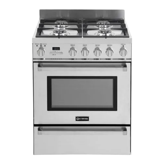
ELECTRIC RANGE
for residential use only
VEFSEE 304 P..
Models:
INSTALLATION INSTRUCTIONS
IMPORTANT - PLEASE READ AND FOLLOW
• Before beginning, please read these instructions completely and carefully.
• Do not remove permanently affixed labels, warnings, or plates from the product. This may
void the warranty.
• Please observe all local and national codes and ordinances.
• Please ensure that this product is properly grounded.
• The installer should leave these instructions with the consumer who should retain
for local inspector's use and for future reference.
Electrical installation must be in accordance with the National Electrical Code, ANSI/NFPA70
- latest edition and/or local codes.
IN CANADA: Electrical installation must be in accordance with the current CSA C22.1
Canadian Electrical Codes Part 1 and/or local codes.
Some models are supplied with a protective film on steel and aluminium
parts. This film must be removed before installing/using the appliance.
THIS RANGE IS FOR RESIDENTIAL USE ONLY
FOR INSTALLER ONLY
R
Advertisement
Table of Contents

Related Manuals for Verona VEFSEE 304 P series


Summary of Contents for Verona VEFSEE 304 P series
- Page 1 ELECTRIC RANGE for residential use only VEFSEE 304 P.. Models: INSTALLATION INSTRUCTIONS IMPORTANT - PLEASE READ AND FOLLOW • Before beginning, please read these instructions completely and carefully. • Do not remove permanently affixed labels, warnings, or plates from the product. This may void the warranty. • Please observe all local and national codes and ordinances. • Please ensure that this product is properly grounded. • The installer should leave these instructions with the consumer who should retain for local inspector’s use and for future reference.
- Page 3 WARNING ! To reduce the risk of tipping the appliance, the appliance must be secured by properly installed anti-tip device packed with the appliance. • ALL RANGES CAN TIP • INJURY TO PERSONS COULD RESULT • INSTALL ANTI-TIP DEVICE PACKED WITH RANGE • SEE INSTALLATION INSTRUCTIONS This appliance is designed and manufactured solely for the cooking of domestic (household) food and in not suitable for any none domestic application and therefore should not be used in a commercial environmement.
-
Page 4: Installation Instructions
INSTALLATION INSTRUCTIONS WARNING! THIS APPLIANCE MUST BE INSTALLED BY A QUALIFIED INSTALLER. Installation must conform with local codes. Improper installation, adjustment, alteration, services, or maintenance can cause injury or property damage. Consult a qualified installer or a service agent. IMPORTANT: The use of suitable protective clothing/gloves is recommended when handling, installing of this appliance. TOOLS NEEDED FOR INSTALLATION (NOT SUPPLIED WITH THE APPLIANCE) T-handle Tape... -
Page 5: General Information
GENERAL INFORMATION WARNING!! WARNING!! 1. ELECTRICAL GROUNDING INSTRUCTIONS This appliance shall not be used for space heating. This The range must be electrically grounded in accordance with information is based on safety considerations. local codes or, in the absence of local codes, with the National Electrical Code, ANSI/NFPA No. 70-latest edition, in Canada 2. AlI openings in the wall behind the appliance and in the floor Canadian Electrical Code. Installation should be made by a under the appliance shall be sealed. Iicensed electrician. 3. Keep appliance area clear and free from combustible Installation should be made by a Iicensed electrician. -
Page 6: Installation
installation PROXIMITY TO SIDE CABINETS 1. This range may be installed directly adjacent to existing 36” (914 mm) high base cabinets. Range dimensions: • width: 29” 7/8 (759 mm) • depth: 24” 13/64 (614.9 mm) • height (without backguard): MIN 35” 21/32 (905.5 mm) - MAX 36” 11/32 (923 mm) • backguard (height): 3” (76 mm) Grounded outlet: should be located from the left to the right side of the range; from 5” 7/16 (138 mm) to 6” 1/8 (155.5 mm) [depending on feet regulation] from the floor. 2. The range CANNOT be installed directly adjacent to sidewalls, tall cabinets, tall appliances, or other side vertical surfaces above 36” (914 mm) high. -
Page 7: Assembling The Backguard
GAS AND ELECTRIC CONNECTION Dotted line showing the position of the range when installed Ref. inch 5” 7/16 - 6” 1/8 (*) 138 - 155.5 (*) (*) : Depending on feet regulation Area for ELECTRICAL connection Fig. 1.2 ASSEMBLING THE BACKGUARD It is mandatory to install the backguard. Assemble the backguard as shown in figure 1.3: • Screw the 2 screws “A” interposing the spacers. • Screw the central screw “B”. Fig. 1.3... - Page 8 PROXIMITY TO SIDE CABINETS STANDARD INSTALLATION Ref. inch Fig. 1.4a 0” 36” 2” 30” minimum 762 minimum 18” minimum 457 minimum 13” maximum 330 maximum 20” minimum 500 minimum Fig. 1.4b...
- Page 9 PROXIMITY TO SIDE CABINETS ISLAND INSTALLATION Ref. inch Fig. 1.5a 0” 36” 2” 30” minimum 762 minimum 18” minimum 457 minimum 13” maximum 330 maximum 20” minimum 500 minimum 12” minimum 305 minimum Fig. 1.5b...
-
Page 10: Anti-Tip Stability Device Installation Instructions
LEVELLING THE RANGE The range is equipped with 4 LEVELLING FEET and may be levelled by screwing or unscrewing the feet (figs. 1.6 - 1.7). It is important to observe the directions of figures 1.6, 1.8a, 1.8b. Fig. 1.6 Supplied with the range Supplied with the range in a separate kit in a separate kit 0” + 5/16” 0 mm + 8 mm + 5/16” + 11/16” + 8 mm Fig. 1.8a Fig. 1.8b + 17.5 mm Fig. 1.7 ANTI-TIP STABILITY DEVICE INSTALLATION INSTRUCTIONS YOU MUST USE STABILITY ANTI TIP BRACKET TO 1. The anti-tip bracket has to be attached as shown on figure below (only rear left side), PREVENT UNIT FROM... -
Page 11: Electrical Connection
electrical connection ELECTRICAL REQUIREMENTS • This appliance must be properly installed and grounded by a qualified technician WARNING in accordance with the National Electrical Code ANSI/NFPA No.70 (latest edition) and local electrical code requirements. IN CANADA: Electrical installation must be in accordance with the current CSA C22.1 Canadian Electrical Codes Part1 and/or TO AVOID ELECTRICAL SHOCK local codes. HAZARD, BEFORE INSTALLING • This appliance may be connected by means of permanent “Hard Wiring” or “Power THE APPLIANCE, SWITCH POWER Supply Cord Kit”. Power supply cord is not supplied, but it is available through your OFF AT THE SERVICE PANEL AND... - Page 12 3-Wire Power Cord Installation (See figures 2.1, 2.2) Fig. 2.1 Screws 1. Remove the Terminal Block Access Plate on the back of the range by unscrewing the 4 fixing Screws (figure 2.1). 2. Check the correct positioning of the Power Cord Bracket as per figure 2.2. 3. Insert the Power Cord through the hole in the Power Cord Bracket; then tighten the Power Cord by using a suitable Strain Relief. Allow enough slack to easily attach the cord terminals to the Terminal Block.
- Page 13 3-Wire Conduit Installation (See figures 2.4 and 2.5) Fig. 2.4 Screws 1. Remove the Terminal Block Access Plate on the back of the range by unscrewing the 4 fixing Screws (figure 2.4). 2. Check the correct positioning of the Conduit Bracket as per figure 2.5. 3. Feed 3/4” trade size Conduit through the hole in the Conduit Bracket and secure to the Conduit Bracket with a Conduit Clamp. 4. Remove the 3 wire terminal nuts and washers from the Terminal Screws Block.
-
Page 14: Wiring Diagram
WIRING DIAGRAM... - Page 16 The manufacturer cannot be held responsible for possible inaccuracies due to printing or transcription errors in the present booklet. The manufacturer reserves the right to make all modifications to its products deemed necessary for manufacture or commercial reasons at any moment and without prior notice, without jeopardising the essential functional and safety characteristics of the appliances. Cod. 1104875 - ß2...
Need help?
Do you have a question about the VEFSEE 304 P series and is the answer not in the manual?
Questions and answers