Table of Contents
Advertisement
Quick Links
Advertisement
Table of Contents

Subscribe to Our Youtube Channel
Related Manuals for Aaeon COM-915 A2.0


Summary of Contents for Aaeon COM-915 A2.0
- Page 1 C O M - 9 1 5 A 2 . 0 COM-915 A2.0 ® ® Intel (Socket 478-based) Pentium ® Celeron M Processors 18-bit Dual-channel LVDS One DDRII 400/533 SODIMM Memory High Definition Audio Interface COM-915 A2.0 Manual 1st Ed. Mar. 2009...
- Page 2 AAEON assumes no liabilities resulting from errors or omissions in this document, or from the use of the information contained herein. AAEON reserves the right to make changes in the product design without notice to its users.
- Page 3 C O M E x p r e s s M o d u l e C O M - 9 1 5 A 2 . 0 Acknowledgments All other products’ name or trademarks are properties of their respective owners. Award is a trademark of Award Software International, Inc.
- Page 4 Before you begin installing your card, please make sure that the following materials have been shipped: • 1 COM-915 A2.0 CPU Module • 1 CD-ROM for manual (in PDF format) and drivers If any of these items should be missing or damaged, please...
- Page 5 ® use Intel Banias-core (0.13μm) CPUs, some components on COM-915 A2.0 have to be changed. Please contact AAEON's sales if you have the special request. 2. Compatibility issue for Transcend USB thumb drive Some Transcend USB thumb drives may not be able to be used as the boot device because of the compatibility issue.
-
Page 6: Table Of Contents
C O M E x p r e s s M o d u l e C O M - 9 1 5 A 2 . 0 Contents Chapter 1 General Information 1.1 Introduction..............1-2 1.2 Features ..............1-3 1.3 Specifications ............1-4 Chapter 2 Quick Installation Guide 2.1 Safety Precautions ............ - Page 7 C O M E x p r e s s M o d u l e C O M - 9 1 5 A 2 . 0 Appendix B I/O Information B.1 I/O Address Map ............B-2 B.2 1 MB Memory Address Map ........B-3 B.3 IRQ Mapping Chart ..........B-4 B.4 DMA Channel Assignments........B-4...
-
Page 8: Chapter 1 General Information
C O M E x p r e s s M o d u l e C O M - 9 1 5 A 2 . 0 Chapter General Information 1- 1 Chapter 1 General Information... -
Page 9: Introduction
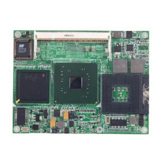
The COM Express CPU module offers flexibility and time-to-market advantages over a fully customized platform. AEON’s COM-915 A2.0 supports 18-bit dual-channel LVDS TFT panel and one DDRII 400/533 SODIMM memory module up to 2GB. High Definition (HD) audio interface can be used by the carrier board’s audio codec. -
Page 10: Features
C O M E x p r e s s M o d u l e C O M - 9 1 5 A 2 . 0 1.2 Features ® ® ® Intel Pentium M/ Celeron M Processors ® Intel 915GME + ICH6M DDRII 400/533 Memory, Max. -
Page 11: Specifications
C O M E x p r e s s M o d u l e C O M - 9 1 5 A 2 . 0 1.3 Specifications System ® ® Intel Socket 478-based Pentium ® M/Celeron M Processor System Memory DDRII SODIMM x 1, supports non-ECC DDRII 400/533 up to... - Page 12 C O M E x p r e s s M o d u l e C O M - 9 1 5 A 2 . 0 I2C x 1 Power Requirement DC +12V operating voltage/ 3.3V for RTC; 2-pin wafer for RTC battery Board Size 4.92”(L) x 3.75”...
- Page 13 C O M E x p r e s s M o d u l e C O M - 9 1 5 A 2 . 0 SDVO Supports SDVO x 2 (Shared with PCI-Express[x16]) Storage PATA x 1 (Two devices); SATAII x USB2.0 x 8 Audio High definition audio...
-
Page 14: Chapter 2 Quick Installation Guide
C O M E x p r e s s M o d u l e C O M - 9 1 5 A 2 . 0 Chapter Quick Installation Guide Notice: The Quick Installation Guide is derived from Chapter 2 of user manual. For other chapters further installation... -
Page 15: Safety Precautions
C O M E x p r e s s M o d u l e C O M - 9 1 5 A 2 . 0 2.1 Safety Precautions Always completely disconnect the power cord from your board whenever you are working on it. -
Page 16: Location Of Connectors/Jumpers And Mechanical
C O M E x p r e s s M o d u l e C O M - 9 1 5 A 2 . 0 2.2 Location of Connectors/ Jumpers and Mechanical Drawings Component Side DIMM1 2 - 3 Chapter 2 Quick Installation Guide... - Page 17 C O M E x p r e s s M o d u l e C O M - 9 1 5 A 2 . 0 Solder Side 2 - 4 Chapter 2 Quick Installation Guide...
-
Page 18: List Of Connectors/ Switch
C O M E x p r e s s M o d u l e C O M - 9 1 5 A 2 . 0 2.3 List of Connectors/ Switch There are a number of connectors and switch in the board that allow you to configure your system to suit your application. -
Page 19: Setting Jumpers
C O M E x p r e s s M o d u l e C O M - 9 1 5 A 2 . 0 2.4 Setting Jumpers You configure your card to match the needs of your application by setting jumpers. -
Page 20: At/Atx Selection (S1)
C O M E x p r e s s M o d u l e C O M - 9 1 5 A 2 . 0 2.5 AT/ATX Selection (S1) Label Function 1 (On), 2 (Off) ATX (Default) 1 (Off), 2 (On) 2.6 COM Express Row AB (CN1) Row A Row B... - Page 21 C O M E x p r e s s M o d u l e C O M - 9 1 5 A 2 . 0 SMB_DAT SUS_S3# SMB_ALERT# SATA0_TX+ SATA1_TX+ SATA0_TX- SATA1_TX- SUS_S4# SUS_STAT# SATA0_RX+ SATA1_RX+ SATA0_RX- SATA1_RX- GND (FIXED) GND (FIXED) SUS_S5#...
- Page 22 C O M E x p r e s s M o d u l e C O M - 9 1 5 A 2 . 0 USB_6_7_OC# USB_4_5_OC# USB4- USB5- USB4+ USB5+ GND (FIXED) GND (FIXED) USB2- USB3- USB2+ USB3+ USB_2_3_OC# USB_0_1_OC#...
- Page 23 C O M E x p r e s s M o d u l e C O M - 9 1 5 A 2 . 0 PCIE_TX2- PCIE_RX2- GPI1 GPO3 PCIE_TX1+ PCIE_RX1+ PCIE_TX1- PCIE_RX1- WAKE0# GPI2 WAKE1# PCIE_TX0+ PCIE_RX0+ PCIE_TX0- PCIE_RX0- GND (FIXED)
- Page 24 C O M E x p r e s s M o d u l e C O M - 9 1 5 A 2 . 0 KBD_RST# VCC_5V_SBY KBD_A20GATE VCC_5V_SBY PCIESLOT1_CLK RSVD PCIESLOT1_CLK# VGA_RED GND (FIXED) GND (FIXED) RSVD VGA_GRN RSVD VGA_BLU...
-
Page 25: Com Express Row Cd (Cn2)
C O M E x p r e s s M o d u l e C O M - 9 1 5 A 2 . 0 A110 GND (FIXED) B110 GND (FIXED) 2.7 COM Express Row CD (CN2) Row C Row D GND (FIXED) GND (FIXED) - Page 26 C O M E x p r e s s M o d u l e C O M - 9 1 5 A 2 . 0 GND (FIXED) GND (FIXED) PCI_REQ0# PCI_AD1 PCI_RESET# PCI_AD3 PCI_AD0 PCI_AD5 PCI_AD2 PCI_AD7 PCI_AD4 PCI_C/BE0# PCI_AD6 PCI_AD9...
- Page 27 C O M E x p r e s s M o d u l e C O M - 9 1 5 A 2 . 0 PCI_AD25 PCI_AD30 PCI_AD27 PCI_IRQC# PCI_AD29 PCI_IRQD# PCI_AD31 PCI_CLKRUN# PCI_IRQA# PCI_IRQB# PCI_CLK GND (FIXED) GND (FIXED) PEG_RX0+ PEG_TX0+...
- Page 28 C O M E x p r e s s M o d u l e C O M - 9 1 5 A 2 . 0 PEG_RXN5 PEG_TXN5 GND (FIXED) GND (FIXED) PEG_RXP6 PEG_TXP6 PEG_RXN6 PEG_TXN6 SDVO_DAT SDVO_CLK PEG_RXP7 PEG_TXP7 PEG_RXN7 PEG_TXN7...
- Page 29 C O M E x p r e s s M o d u l e C O M - 9 1 5 A 2 . 0 PEG_RXP13 PEG_TXP13 PEG_RXN13 PEG_TXN13 RSVD PEG_RXP14 PEG_TXP14 PEG_RXN14 PEG_TXN14 C100 GND (FIXED) D100 GND (FIXED) C101 PEG_RXP15...
-
Page 30: Chapter 3 Award Bios Setup
C O M E x p r e s s M o d u l e C O M - 9 1 5 A 2 . 0 Chapter Award BIOS Setup Chapter 3 Award BIOS Setup 3-1... - Page 31 C O M E x p r e s s M o d u l e C O M - 9 1 5 A 2 . 0 3.1 System Test and Initialization These routines test and initialize board hardware. If the routines encounter an error during the tests, you will either hear a few short beeps or see an error message on the screen.
- Page 32 C O M E x p r e s s M o d u l e C O M - 9 1 5 A 2 . 0 3.2 Award BIOS Setup Awards BIOS ROM has a built-in Setup program that allows users to modify the basic system configuration.
- Page 33 Save CMOS value changes to CMOS and exit setup. Exit Without Saving Abandon all CMOS value changes and exit setup. You can refer to the "AAEON BIOS Item Description.pdf" file in the CD for the meaning of each setting in this chapter. Chapter 3 Award BIOS Setup 3-4...
-
Page 34: Chapter 4 Driver Installation
C O M E x p r e s s M o d u l e C O M - 9 1 5 A 2 . 0 Chapter Driver Installation Chapter 4 Driver Installation... - Page 35 C O M E x p r e s s M o d u l e C O M - 9 1 5 A 2 . 0 The COM-915 A2.0 comes with an AutoRun CD-ROM that contains all drivers and utilities that can help you to install the driver automatically.
- Page 36 C O M E x p r e s s M o d u l e C O M - 9 1 5 A 2 . 0 4.1 Installation: Insert the COM-915 A2.0 CD-ROM into the CD-ROM drive. And install the drivers from Step 1 to Step 5 in order. ®...
- Page 37 C O M E x p r e s s M o d u l e C O M - 9 1 5 A 2 . 0 Step 4 –Install Realtech Audio Driver 1. Click on the Step 4 –Realtek Audio Driver folder and select the OS folder your system is 2.
-
Page 38: Appendix A Programming The Watchdog Timer
C O M E x p r e s s M o d u l e C O M - 9 1 5 A 2 . 0 Appendix Programming the Watchdog Timer Appendix A Programming the Watchdog Timer A-1... -
Page 39: Programming
C O M E x p r e s s M o d u l e C O M - 9 1 5 A 2 . 0 A.1 Programming COM-915 A2.0 utilizes ITE 8712 chipset as its watchdog timer controller. Below are the procedures to complete its configuration and the AAEON intial watchdog timer program is also attached based on which you can develop customized program to fit your application. - Page 40 C O M E x p r e s s M o d u l e C O M - 9 1 5 A 2 . 0 There are three steps to complete the configuration setup: (1) Enter the MB PnP Mode; (2) Modify the data of configuration registers; (3) Exit the MB PnP Mode.
- Page 41 C O M E x p r e s s M o d u l e C O M - 9 1 5 A 2 . 0 WatchDog Timer Configuration Registers Configure Control (Index=02h) This register is write only. Its values are not sticky; that is to say, a hardware reset will automatically clear the bits, and does not require the software to clear them.
- Page 42 C O M E x p r e s s M o d u l e C O M - 9 1 5 A 2 . 0 WatchDog Timer Configuration Register (Index=72h, Default=00h) WatchDog Timer Time-out Value Register (Index=73h, Default=00h) Appendix A Programming the Watchdog Timer A-5...
-
Page 43: It8712 Watchdog Timer Initial Program
C O M E x p r e s s M o d u l e C O M - 9 1 5 A 2 . 0 A.2 IT8712 Watchdog Timer Initial Program .MODEL SMALL .CODE Main: CALL Enter_Configuration_mode CALL Check_Chip mov cl, 7 call Set_Logic_Device ;time setting... - Page 44 C O M E x p r e s s M o d u l e C O M - 9 1 5 A 2 . 0 ; game port enable mov cl, 9 call Set_Logic_Device Initial_OK: CALL Exit_Configuration_mode MOV AH,4Ch INT 21h Enter_Configuration_Mode PROC NEAR MOV SI,WORD PTR CS:[Offset Cfg_Port]...
- Page 45 C O M E x p r e s s M o d u l e C O M - 9 1 5 A 2 . 0 Exit_Configuration_Mode ENDP Check_Chip PROC NEAR MOV AL,20h CALL Read_Configuration_Data CMP AL,87h JNE Not_Initial MOV AL,21h CALL Read_Configuration_Data CMP AL,12h...
- Page 46 C O M E x p r e s s M o d u l e C O M - 9 1 5 A 2 . 0 MOV DX,WORD PTR CS:[Cfg_Port+06h] IN AL,DX Read_Configuration_Data ENDP Write_Configuration_Data PROC NEAR MOV DX,WORD PTR CS:[Cfg_Port+04h] OUT DX,AL XCHG AL,AH MOV DX,WORD PTR CS:[Cfg_Port+06h]...
- Page 47 C O M E x p r e s s M o d u l e C O M - 9 1 5 A 2 . 0 push ax push cx xchg al,cl mov cl,07h call Superio_Set_Reg pop cx pop ax Set_Logic_Device endp ;Select 02Eh->Index Port, 02Fh->Data Port Cfg_Port DB 087h,001h,055h,055h...
-
Page 48: Appendix B I/O Information
C O M E x p r e s s M o d u l e C O M - 9 1 5 A 2 . 0 Appendix I/O Information B - 1 Appendix B I/O Information... -
Page 49: I/O Address Map
C O M E x p r e s s M o d u l e C O M - 9 1 5 A 2 . 0 B.1 I/O Address Map B - 2 Appendix B I/O Information... -
Page 50: St Mb Memory Address Map
C O M E x p r e s s M o d u l e C O M - 9 1 5 A 2 . 0 B.2 1 MB Memory Address Map B - 3 Appendix B I/O Information... -
Page 51: Irq Mapping Chart
C O M E x p r e s s M o d u l e C O M - 9 1 5 A 2 . 0 B.3 IRQ Mapping Chart B.4 DMA Channel Assignments B - 4 Appendix B I/O Information...
Need help?
Do you have a question about the COM-915 A2.0 and is the answer not in the manual?
Questions and answers