Table of Contents
Advertisement
Quick Links
Download this manual
See also:
User Manual
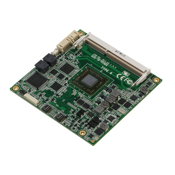
C O M E x p r e s s M o d u l e
C O M - K B
COM-KB
®
AMD
Embedded G-series APU (SoC)
AMD® GX-420CA Quad-core 2.0GHz SOC
with AMD Radeon™ HD 8400E Graphics
AMD® GX-217GA Dual-core 1.65GHz SOC
with AMD Radeon™ HD 8280E Graphics
Gigabit Ethernet
2 SATA 6.0Gb/s
8 USB2.0, 2 USB3.0
5 PCI-E[x1]
COM Express CPU Module
COM-KB Manual 1st Ed.
February 21, 2014
Advertisement
Table of Contents

Related Manuals for Aaeon COM-KB


Summary of Contents for Aaeon COM-KB
- Page 1 AMD® GX-420CA Quad-core 2.0GHz SOC with AMD Radeon™ HD 8400E Graphics AMD® GX-217GA Dual-core 1.65GHz SOC with AMD Radeon™ HD 8280E Graphics Gigabit Ethernet 2 SATA 6.0Gb/s 8 USB2.0, 2 USB3.0 5 PCI-E[x1] COM Express CPU Module COM-KB Manual 1st Ed. February 21, 2014...
- Page 2 AAEON assumes no liabilities resulting from errors or omissions in this document, or from the use of the information contained herein. AAEON reserves the right to make changes in the product design without notice to its users.
- Page 3 C O M E x p r e s s M o d u l e C O M - K B Acknowledgments All other products’ name or trademarks are properties of their respective owners. AMI is a trademark of American Megatrends Inc. ®...
- Page 4 Before you begin installing your card, please make sure that the following materials have been shipped: M2.5 Screw DVD-ROM for manual (in PDF format) and drivers COM-KB If any of these items should be missing or damaged, please contact your distributor or sales representative immediately.
-
Page 5: Table Of Contents
C O M E x p r e s s M o d u l e C O M - K B Contents Chapter 1 General Information 1.1 Introduction ..............1-2 1.2 Features ..............1-3 1.3 Specifications ............1-4 Chapter 2 Quick Installation Guide 2.1 Safety Precautions ............ - Page 6 C O M E x p r e s s M o d u l e C O M - K B 2.17 ROW_AB Connector (CN9) ........2-14 2.18 ROW_CD Connector (CN10) ........2-14 2.19 DDR3 SODIMM Connector (DIMM1) ...... 2-14 2.20 Standard DDR3 SODIMM Connector .....
-
Page 7: Chapter 1 General Information
C O M E x p r e s s M o d u l e C O M - K B Chapter General Information 1- 1 Chapter 1 General Information... -
Page 8: Introduction
AAEON, a leading embedded board manufacturer, is pleased to announce the debut of their new generation COM Express Module-- COM-KB. The COM-KB is a cutting-edge product that provides high performance and low power consumption in the embedded market. COM-KB adopts the latest AMD embedded G-Series SoC processor. -
Page 9: Features
C O M E x p r e s s M o d u l e C O M - K B 1.2 Features AMD® Embedded G-Series SOC APU AMD® GX-415GA Quad-core 1.5GHz SOC with AMD Radeon™ HD 8330E Graphics ... -
Page 10: Specifications
C O M E x p r e s s M o d u l e C O M - K B 1.3 Specifications System Form Factor COM Express Basic module, Pin-out Type 6, COM. 0 Rev. 2.1 Processor Onboard AMD Embedded G-series APU (SoC) Processors... - Page 11 C O M E x p r e s s M o d u l e C O M - K B Storage Temperature -40°F ~ 176°F (-40°C ~ 80°C) Operating Humidity 0% ~ 90% relative humidity, non-condensing ®...
-
Page 12: Chapter 2 Quick Installation Guide
C O M E x p r e s s M o d u l e C O M - K B Chapter Quick Installation Guide Chapter 2 Quick Installation Guide... -
Page 13: Safety Precautions
C O M E x p r e s s M o d u l e C O M - K B 2.1 Safety Precautions Always completely disconnect the power cord from your board whenever you are working on it. Do not make connections while the power is on, because a sudden rush of power can damage sensitive electronic components. -
Page 14: Location Of Connectors And Jumpers
C O M E x p r e s s M o d u l e C O M - K B 2.2 Location of Connectors and Jumpers Component Side Chapter 2 Quick Installation Guide... - Page 15 C O M E x p r e s s M o d u l e C O M - K B Solder Side Chapter 2 Quick Installation Guide...
-
Page 16: Mechanical Drawing
C O M E x p r e s s M o d u l e C O M - K B 2.3 Mechanical Drawing Component Side Chapter 2 Quick Installation Guide... - Page 17 C O M E x p r e s s M o d u l e C O M - K B Solder Side Chapter 2 Quick Installation Guide...
-
Page 18: List Of Jumpers
C O M E x p r e s s M o d u l e C O M - K B 2.4 List of Jumpers The board has a number of jumpers that allow you to configure your system to suit your application. The table below shows the function of each of the board's jumpers: Jumpers Label... -
Page 19: List Of Connectors
C O M E x p r e s s M o d u l e C O M - K B 2.5 List of Connectors The board has a number of connectors that allow you to configure your system to suit your application. The table below shows the function of each board's connectors: Connectors Label... -
Page 20: Setting Jumpers
C O M E x p r e s s M o d u l e C O M - K B 2.6 Setting Jumpers You configure your card to match the needs of your application by setting jumpers. A jumper is the simplest kind of electric switch. It consists of two metal pins and a small metal clip (often protected by a plastic cover) that slides over the pins to connect them. -
Page 21: Dp0 (Ddi1) Selection/Dp1 (Ddi2) Selection (Sw1)
C O M E x p r e s s M o d u l e C O M - K B 2.7 DP0 (SW1) (DDI1) Selection/DP1 (DDI2) Selection Function : DP 1 Off 2 Off Function : HDMI/DVI 1 Off 2 On Function : eDP 1 On... -
Page 22: Power Type Selection/Rtc Clear/Ddr3 Voltage
C O M E x p r e s s M o d u l e C O M - K B 2.8 Power Type Selection/RTC Clear/DDR3 Voltage Selection/LVDS Backlight Selection (SW2) Function 1 On ATX (Default) 1 Off 2 On RTC Clear 2 Off RTC reserved (Default) -
Page 23: Battery Connector (Cn4)
C O M E x p r e s s M o d u l e C O M - K B SPI_CS#_F 2.12 Battery Connector (CN4) Signal +3V From battery 2.13 EDP/18BIT LVDS Connector (CN5) Signal +3.3V with Fuse +3.3V with Fuse EDP_TX2_N (18BIT LVDS: L0N) EDP_TX2_P (18BIT LVDS: L0P) -
Page 24: 18Bit Lvds Connector (Cn6)
C O M E x p r e s s M o d u l e C O M - K B VOL_CON BLON EDP_HPD +12V with Fuse +12V with Fuse +12V with Fuse +12V with Fuse 2.14 18BIT LVDS Connector (CN6) Signal +12V with Fuse VOL_PWM (SW2 POS 4) -
Page 25: Spi Ec Program Connector (Cn8)
C O M E x p r e s s M o d u l e C O M - K B LPC FRAME# LPC_RST# LPC CLK1 LPC DRQ0 SERIRQ 2.16 SPI EC Program connector (CN8) Signal FMISO_F FSCK_F +3V3_EC FMOSI_F FSCE#_F 2.17 ROW_AB connector (CN9) - Page 26 C O M E x p r e s s M o d u l e C O M - K B Below Table for China RoHS Requirements 产品中有毒有害物质或元素名称及含量 AAEON Main Board/ Daughter Board/ Backplane 有毒有害物质或元素 部件名称 铅 汞 镉...
- Page 27 C O M E x p r e s s M o d u l e C O M - K B Chapter BIOS Setup Chapter 3 AMI BIOS Setup 3-1...
-
Page 28: System Test And Initialization
3. The system configuration is reset by Clear-CMOS jumper 4. The CMOS memory has lost power and the configuration information has been erased. The COM-KB CMOS memory has an integral lithium battery backup for data retention. You have to replace the battery when it finally runs down. -
Page 29: Ami Bios Setup
C O M E x p r e s s M o d u l e C O M - K B 3.2 AMI BIOS Setup AMI BIOS ROM has a built-in Setup program that allows users to modify the basic system configuration. This type of information is stored in battery-backed CMOS RAM and BIOS NVRAM so that it retains the Setup information when the power is turned off. - Page 30 C O M E x p r e s s M o d u l e C O M - K B Setup Menu Setup submenu: Main Chapter 3 AMI BIOS Setup 3-4...
- Page 31 C O M E x p r e s s M o d u l e C O M - K B Setup submenu: Advanced Chapter 3 AMI BIOS Setup 3-5...
- Page 32 C O M E x p r e s s M o d u l e C O M - K B ACPI Settings Options summary: ACPI Sleep State S3 only (Suspend to RAM) Optimal Default, Failsafe Default Select the ACPI state used for System Suspend Chapter 3 AMI BIOS Setup 3-6...
- Page 33 C O M E x p r e s s M o d u l e C O M - K B CPU Configuration Chapter 3 AMI BIOS Setup 3-7...
- Page 34 C O M E x p r e s s M o d u l e C O M - K B IDE Configuration (IDE) Options summary: OnChip SATA Type Legacy IDE Optimal Default, Failsafe Default AHCI Chapter 3 AMI BIOS Setup 3-8...
- Page 35 C O M E x p r e s s M o d u l e C O M - K B USB Configuration Options summary: Legacy USB Support Enabled Optimal Default, Failsafe Default Disabled Auto Enables BIOS Support for Legacy USB Support. When enabled, USB can be functional in legacy environment like DOS.
- Page 36 C O M E x p r e s s M o d u l e C O M - K B Dynamic Digital IO Options summary: GPI0~GPI3 Input Optimal Default, Failsafe Default Direction Output Set GPIO as Input or Output GPO0~GPI3 Input Direction...
- Page 37 C O M E x p r e s s M o d u l e C O M - K B Power Management Options summary: Power Mode ATX Type Optimal Default, Failsafe Default AT Type Select power supply mode. Restore on Power Last State Optimal Default, Failsafe Default...
- Page 38 C O M E x p r e s s M o d u l e C O M - K B S5 RTC Wake Settings (Fixed Time) Options summary: Wake system with Disabled Optimal Default, Failsafe Default Fixed Time Enabled En/Disable System wake on alarm event.
- Page 39 C O M E x p r e s s M o d u l e C O M - K B S5 RTC Wake Settings (Dynamic Time) Options summary: Wake system with Disabled Optimal Default, Failsafe Default Dynamic Time Enabled En/Disable System wake on alarm event.
- Page 40 C O M E x p r e s s M o d u l e C O M - K B On-Module IO Configuration Chapter 3 AMI BIOS Setup 3-14...
- Page 41 C O M E x p r e s s M o d u l e C O M - K B Serial Port 9 Configuration Options summary: Serial Port Disabled Enabled Optimal Default, Failsafe Default En/Disable Serial Port (COM) Change Settings Auto Optimal Default, Failsafe...
- Page 42 C O M E x p r e s s M o d u l e C O M - K B Serial Port 10 Configuration Options summary: Serial Port Disabled Enabled Optimal Default, Failsafe Default En/Disable Serial Port (COM) Change Settings Auto Optimal Default, Failsafe...
- Page 43 C O M E x p r e s s M o d u l e C O M - K B On-Module H/W Monitor Chapter 3 AMI BIOS Setup 3-17...
- Page 44 C O M E x p r e s s M o d u l e C O M - K B CPU Smart Fan Mode Configuration(Full Mode) Options summary: CPU Smart Fan Full Mode Optimal Default, Failsafe control Default Manual Mode by PWM Auto Mode by PWM Chapter 3 AMI BIOS Setup 3-18...
- Page 45 C O M E x p r e s s M o d u l e C O M - K B CPU Smart Fan Mode Configuration(Manual Mode by PWM) Options summary: Manual Setting Optimal Default, Failsafe Default 0 - 100 Set Fan at fixed Duty-Cycle Min=0 Max=100 Please input Decimal number Chapter 3 AMI BIOS Setup 3-19...
- Page 46 C O M E x p r e s s M o d u l e C O M - K B CPU Smart Fan Mode Configuration(Auto Mode by PWM) Options summary: Temperature Of Optimal Default, Failsafe Start Default Temperature Of Optimal Default, Failsafe Default Start PWM...
- Page 47 C O M E x p r e s s M o d u l e C O M - K B Setup submenu: Chipset Chapter 3 AMI BIOS Setup 3-21...
- Page 48 C O M E x p r e s s M o d u l e C O M - K B North Bridge Options summary: PCIE GEN Speed GEN1 GEN2 Optimal Default, Failsafe Default PCIE GEN speed Chapter 3 AMI BIOS Setup 3-22...
- Page 49 C O M E x p r e s s M o d u l e C O M - K B GFX Configuration Options summary: DP0 Output Mode Optimal Default, Failsafe Default Single Link DVI-D HDMI LVDS EDID Panel Support Disabled (When DP0 Output Enabled...
- Page 50 C O M E x p r e s s M o d u l e C O M - K B LVDS (LVDS2) Disabled Enabled Optimal Default, Failsafe Default LVDS (LVDS2) Panel 640x480,18bit,60Hz Type 800x480,18bit,60Hz 800x600,18bit,60Hz 1024x600,18bit,60Hz 1024x768,18bit,60Hz Optimal Default, Failsafe Default 1024x768,24bit,60Hz 1280x768,24bit,60Hz 1280x1024,48bit,60Hz...
- Page 51 C O M E x p r e s s M o d u l e C O M - K B South Bridge Options summary: HD Audio Azalia Enabled Optimal Default, Failsafe Default Device Disabled SD Mode Disabled Optimal Default, Failsafe Default ADMA SB Clock Spread Disabled...
- Page 52 C O M E x p r e s s M o d u l e C O M - K B Setup submenu: Boot Chapter 3 AMI BIOS Setup 3-26...
- Page 53 C O M E x p r e s s M o d u l e C O M - K B Options summary: Bootup NumLock State Default Select the keyboard NumLock state Quiet Boot Disabled Enabled Default En/Disable showing boot logo. Launch I82579LM PXE Disabled Default...
- Page 54 C O M E x p r e s s M o d u l e C O M - K B BBS Priorities Chapter 3 AMI BIOS Setup 3-28...
- Page 55 C O M E x p r e s s M o d u l e C O M - K B Security Change User/Supervisor Password You can install a Supervisor password, and if you install a supervisor password, you can then install a user password. A user password does not provide access to many of the features in the Setup utility.
- Page 56 C O M E x p r e s s M o d u l e C O M - K B Setup submenu: Exit Chapter 3 AMI BIOS Setup 3-30...
-
Page 57: Chapter 4 Driver Installation
C O M E x p r e s s M o d u l e C O M - K B Chapter Driver Installation 4 -1 Chapter 4 Driver Installation... - Page 58 C O M E x p r e s s M o d u l e C O M - K B The COM-KB comes with an AutoRun DVD-ROM that contains all drivers and utilities that can help you to install the driver automatically.
- Page 59 C O M E x p r e s s M o d u l e C O M - K B 4.1 Installation: Insert the COM-KB DVD-ROM into the DVD-ROM drive. And install the drivers from Step 1 to Step 4 in order. Step 1 – Install Chipset & Display Driver Click on the Step1 - Chipset &...
- Page 60 C O M E x p r e s s M o d u l e C O M - K B Step 4– Install Serial Port Driver ® For Windows XP 32-bit, select the folder of WINXP_32 and double click on the patch.bat ®...
- Page 61 C O M E x p r e s s M o d u l e C O M - K B 2. Change User Account Control Settings to [Never notify] 3. Reboot and Administrator login. 4 -5 Chapter 4 Driver Installation...
- Page 62 C O M E x p r e s s M o d u l e C O M - K B 4. To run patch.bat with [Run as administrator]. 4 -6 Chapter 4 Driver Installation...
-
Page 63: Appendix A Programming The Watchdog Timer
C O M E x p r e s s M o d u l e C O M - K B Appendix Programming the Watchdog Timer Appendix A Programming the Watchdog Timer A-1... -
Page 64: Watchdog Timer Initial Program
C O M E x p r e s s M o d u l e C O M - K B A.1 Watchdog Timer Initial Program Table 1 : Embedded BRAM relative register table Default Value Note Index 0x284 BRAM Index Register (Note1) Data 0x285 BRAM Data Register (Note2) Logical Device Number ... - Page 65 C O M E x p r e s s M o d u l e C O M - K B ************************************************************************************ // Embedded BRAM relative definition (Please reference to Table 1) #define byte EcBRAMIndex //This parameter is represented from Note1 #define byte EcBRAMData //This parameter is represented from Note2 #define byte BRAMLDNReg //This parameter is represented from Note3 #define byte BRAMFnDataReg //This parameter is represented from Note4 #define ...
- Page 66 C O M E x p r e s s M o d u l e C O M - K B ************************************************************************************ Main VOID (){ // Procedure : AaeonWDTConfig // (byte)Timer : Time of WDT timer.(0x00~0xFF) // (boolean)Unit : Select time unit(0: second, 1: minute). AaeonWDTConfig(); // Procedure : AaeonWDTEnable // This procudure will enable the WDT counting. AaeonWDTEnable(); ...
- Page 67 C O M E x p r e s s M o d u l e C O M - K B ************************************************************************************ // Procedure : AaeonWDTEnable AaeonWDTEnable () VOID { WDTEnableDisable( ); } // Procedure : AaeonWDTConfig AaeonWDTConfig () VOID { // Disable WDT counting WDTEnableDisable( ); // WDT relative parameter setting ...
- Page 68 C O M E x p r e s s M o d u l e C O M - K B ************************************************************************************ ECBRAMWriteByte(byte OPReg, byte OPBit, byte Value) VOID { IOWriteByte(EcBRAMIndex, 0x10); IOWriteByte(EcBRAMData, BRAMLDNReg); IOWriteByte(EcBRAMIndex, 0x11); IOWriteByte(EcBRAMData, BRAMFnDataReg); IOWriteByte(EcBRAMIndex, 0x13 + OPReg); IOWriteByte(EcBRAMData, Value); IOWriteByte(EcBRAMIndex, 0x12); IOWriteByte(EcBRAMData, 0x30); //Write start } ...
-
Page 69: Appendix B I/O Information
C O M E x p r e s s M o d u l e C O M - K B Appendix I/O Information B - 1 Appendix B I/O Information... -
Page 70: I/O Address Map
C O M E x p r e s s M o d u l e C O M - K B B.1 I/O Address Map B - 2 Appendix B I/O Information... - Page 71 C O M E x p r e s s M o d u l e C O M - K B B - 3 Appendix B I/O Information...
-
Page 72: Memory Address Map
C O M E x p r e s s M o d u l e C O M - K B B.2 Memory Address Map B - 4 Appendix B I/O Information... -
Page 73: Irq Mapping Chart
C O M E x p r e s s M o d u l e C O M - K B B.3 IRQ Mapping Chart B - 5 Appendix B I/O Information... - Page 74 C O M E x p r e s s M o d u l e C O M - K B B - 6 Appendix B I/O Information...
- Page 75 C O M E x p r e s s M o d u l e C O M - K B B - 7 Appendix B I/O Information...
-
Page 76: Dma Channel Assignments
C O M E x p r e s s M o d u l e C O M - K B B.4 DMA Channel Assignments B - 8 Appendix B I/O Information...
Need help?
Do you have a question about the COM-KB and is the answer not in the manual?
Questions and answers