Table of Contents

Related Manuals for Aaeon NanoCOM-U15


Summary of Contents for Aaeon NanoCOM-U15
- Page 1 N a n o C O M - U 1 5 NanoCOM-U15 ® Intel Atom Z530/Z510 Processor 24-bit Single Channel LVDS Onboard DDRII 533 Memory High Definition Audio 1 SATA II, 8 USB2.0 NanoCOM-U15 Manual Rev.A 1st Ed. May 2009...
- Page 2 AAEON assumes no liabilities resulting from errors or omissions in this document, or from the use of the information contained herein. AAEON reserves the right to make changes in the product design without notice to its users.
- Page 3 C O M E x p r e s s M o d u l e N a n o C O M - U 1 5 Acknowledgments All other products’ name or trademarks are properties of their respective owners. Award is a trademark of Award Software International, Inc.
- Page 4 N a n o C O M - U 1 5 Packing List Before you begin installing your card, please make sure that the following materials have been shipped: • 1 NanoCOM-U15 CPU module • 1 CD-ROM for manual (in PDF format) and drivers • 4 M2.5 screws If any of these items should be missing or damaged, please contact your distributor or sales representative immediately.
- Page 5 If you need the function of Wake-On-LAN or PXE, AAEON can provide the custom BIOS to you. 2. USB Client Port The NanoCOM-U15 supports 8 USB ports. Port 7 can be the host or client port. It can be chosen via BIOS. 3. Legacy and legacy-free BIOS The NanoCOM-U15 equips with legacy-free BIOS in default.
-
Page 6: Table Of Contents
2.8 SDVO Connector (CN3) ..........2-5 2.9 COM Express Row A/B Connector (CN4)....2-6 2.10 Storage Support Matrix ........... 2-11 2.11 Function Matrix for NanoCOM-U15 with ECB-951D2-12 Chapter 3 Award BIOS Setup 3.1 System Test and Initialization........3-2 3.2 Award BIOS Setup ............ 3-3 Chapter 4 Driver Installation 4.1 Installation .............. - Page 7 C O M E x p r e s s M o d u l e N a n o C O M - U 1 5 Appendix A Programming The Watchdog Timer A.1 Programming ............A-2 Appendix B I/O Information B.1 I/O Address Map ............B-2 B.2 Memory Address Map..........B-3 B.3 IRQ Mapping Chart ..........B-4...
-
Page 8: Chapter 1 General Information
C O M E x p r e s s M o d u l e N a n o C O M - U 1 5 Chapter General Information 1- 1 Chapter 1 General Information... -
Page 9: Introduction
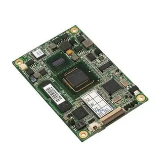
The COM Express CPU module offers flexibility and time-to-market advantages over a fully customized platform. AAEON’s NanoCOM-U15 supports up to 24-bit single channel LVDS interface and supports onboard DDRII 533 memory chip up to 1GB. A high definition audio interface is available to connect to an audio codec on the carrier board. -
Page 10: Features
C O M E x p r e s s M o d u l e N a n o C O M - U 1 5 1.2 Features ® Onboard Intel Atom™ Z530/Z510 Processor ® Intel System Controller Hub US15W Onboard DDRII 533 Memory Chip, Max. -
Page 11: Specifications
C O M E x p r e s s M o d u l e N a n o C O M - U 1 5 1.3 Specifications System ® Processor Intel Atom™ Z530/Z510 Processor Z530: 1.6GHz/ FSB 533MHz Z510: 1.1GHz/ FSB 400MHz System Memory Onboard DDRII 533 memory chip,... - Page 12 C O M E x p r e s s M o d u l e N a n o C O M - U 1 5 LPC bus x 1 SMBus x 1 Power Requirement Wide DC Input Range, +4.75V to +14.7V 2-pin wafer for RTC battery Board Size...
- Page 13 C O M E x p r e s s M o d u l e N a n o C O M - U 1 5 LVDS SDVO SDVO connector x 1 Storage 1. PATA SSD onboard (Master device), Max. 4GB (Optional) 2.
-
Page 14: Chapter 2 Quick Installation Guide
C O M E x p r e s s M o d u l e N a n o C O M - U 1 5 Chapter Quick Installation Guide Notice: The Quick Installation Guide is derived from Chapter 2 of user manual. For other chapters further installation... -
Page 15: Safety Precautions
C O M E x p r e s s M o d u l e N a n o C O M - U 1 5 2.1 Safety Precautions Always completely disconnect the power cord from your board whenever you are working on it. -
Page 16: Location Of Connectors/Jumpers & Mechanical Drawings
C O M E x p r e s s M o d u l e N a n o C O M - U 1 5 2.2 Location of Connectors/ Jumpers & Mechanical Drawings Component Side Solder Side 2 - 3 Chapter 2 Quick Installation Guide... -
Page 17: List Of Jumpers/ Connectors/ Switches
C O M E x p r e s s M o d u l e N a n o C O M - U 1 5 2.3 List of Jumpers/ Connectors/ Switches The board has a number of jumpers that allow you to configure your system to suit your application. -
Page 18: Rtc Battery Connector (Bat1)
C O M E x p r e s s M o d u l e N a n o C O M - U 1 5 2.6 RTC Battery Connector (BAT1) Signal +3.3V_BAT 2.7 SCI & SMI Connector (CN2) Signal EC_SCI SMI#... -
Page 19: Com Express Row A/B Connector (Cn4)
C O M E x p r e s s M o d u l e N a n o C O M - U 1 5 2.9 COM Express Row A/B Connector (CN4) Row A Row B GND (FIXED) GND (FIXED) GBE0_MDI3- GBE0_ACT#... - Page 20 C O M E x p r e s s M o d u l e N a n o C O M - U 1 5 N.C. N.C. SUS_S5# PWR_OK N.C. N.C. N.C. N.C. N.C. IDELED# N.C. AC_SYNC AC_SDIN1 AC_RST# AC_SDIN0 GND (FIXED)
- Page 21 C O M E x p r e s s M o d u l e N a n o C O M - U 1 5 VCC_RTC N.C. EXCD0_PERST# N.C. N.C. SYS_RESET# LPC_SERIRQ CB_RESET# GND (FIXED) GND (FIXED) N.C. N.C.
- Page 22 C O M E x p r e s s M o d u l e N a n o C O M - U 1 5 LVDS_A0+ N.C. LVDS_A0- N.C. LVDS_A1+ N.C. LVDS_A1- N.C. LVDS_A2+ N.C. LVDS_A2- N.C. LVDS_VDD_EN N.C.
- Page 23 C O M E x p r e s s M o d u l e N a n o C O M - U 1 5 RSVD N.C. N.C. VCC_12V N.C. VCC_12V N.C. VCC_12V N.C. A100 GND (FIXED) B100 GND (FIXED) A101 VCC_12V...
-
Page 24: Storage Support Matrix
C O M E x p r e s s M o d u l e N a n o C O M - U 1 5 2.10 Storage Support Matrix ECB-951D Module (Function availability) Model Name Storage Description PATA SATA (IDE) SDIO... -
Page 25: Function Matrix For Nanocom-U15 With Ecb-951D2-12
C O M E x p r e s s M o d u l e N a n o C O M - U 1 5 2.11 Function Matrix for NanoCOM-U15 with ECB-951D Legacy-free Legacy Legacy-free BIOS BIOS BIOS... - Page 26 C O M E x p r e s s M o d u l e N a n o C O M - U 1 5 IDE Connector CN14 (For 1.8” HDD) CN15 COM2 Connector Pass No function LAN Connector CN16 Pass Pass...
- Page 27 C O M E x p r e s s M o d u l e N a n o C O M - U 1 5 CN34 K/B Connector Pass No function Audio Connector CN35 Pass Pass (Reserved) COM2 Connector CN36 (For Extended Pass...
- Page 28 C O M E x p r e s s M o d u l e N a n o C O M - U 1 5 Note: (1.1) Please accompany with TF-ECB-951D-A10-01 to run the test. When you want to test legacy-free BIOS and know its limitations, please use the following instructions to disable EC in ECB-951D.
- Page 29 C O M E x p r e s s M o d u l e N a n o C O M - U 1 5 (1.3) R280, R286 R280 R286 LVDS 640*480: No full screen on BIOS setup screen. 2 - 16 Chapter 2 Quick Installation Guide...
- Page 30 C O M E x p r e s s M o d u l e N a n o C O M - U 1 5 Below Table for China RoHS Requirements 产品中有毒有害物质或元素名称及含量 AAEON Main Board/ Daughter Board/ Backplane 有毒有害物质或元素 部件名称 铅...
-
Page 31: Chapter 3 Award Bios Setup
C O M E x p r e s s M o d u l e N a n o C O M - U 1 5 Chapter Award BIOS Setup Chapter 3 Award BIOS Setup 3-1... - Page 32 C O M E x p r e s s M o d u l e N a n o C O M - U 1 5 3.1 System Test and Initialization These routines test and initialize board hardware. If the routines encounter an error during the tests, you will either hear a few short beeps or see an error message on the screen.
- Page 33 C O M E x p r e s s M o d u l e N a n o C O M - U 1 5 3.2 Award BIOS Setup Awards BIOS ROM has a built-in Setup program that allows users to modify the basic system configuration.
- Page 34 Save CMOS value changes to CMOS and exit setup. Exit Without Saving Abandon all CMOS value changes and exit setup. You can refer to the "AAEON BIOS Item Description.pdf" file in the CD for the meaning of each setting in this chapter. Chapter 3 Award BIOS Setup 3-4...
-
Page 35: Chapter 4 Driver Installation
C O M E x p r e s s M o d u l e N a n o C O M - U 1 5 Chapter Driver Installation 4 -1 Chapter 4 Driver Installation... - Page 36 C O M E x p r e s s M o d u l e N a n o C O M - U 1 5 The NanoCOM-U15 comes with an AutoRun CD-ROM that contains all drivers and utilities that can help you to install the driver automatically.
- Page 37 C O M E x p r e s s M o d u l e N a n o C O M - U 1 5 4.1 Installation: Insert the NanoCOM-U15 CD-ROM into the CD-ROM drive. And install the drivers from Step 1 to Step 6 in order. Step 1 – Install INF Driver 1.
- Page 38 C O M E x p r e s s M o d u l e N a n o C O M - U 1 5 Step 4 –Install Audio Driver (For ECB-951D) 1. Click on the Step 4 –Audio folder and select the OS folder your system is 2.
-
Page 39: Appendix A Programming The Watchdog Timer
C O M E x p r e s s M o d u l e N a n o C O M - U 1 5 Appendix Programming the Watchdog Timer Appendix A Programming the Watchdog Timer A-1... -
Page 40: Programming
C O M E x p r e s s M o d u l e N a n o C O M - U 1 5 A.1 Programming #include <stdio.h> #include <conio.h> void functionA(); void functionB(); void functionC(); void functionD(); void functionE();... - Page 41 C O M E x p r e s s M o d u l e N a n o C O M - U 1 5 char option_var='x'; //device ID(smbus):6Eh,index:03h data:03h outportb(SMBus_Port+0x04,0x6E); delay(5); outportb(SMBus_Port+0x02,0x54); delay(5) ; outportb(SMBus_Port+0x03,0x00); delay(5) ; outportb(SMBus_Port+0x05,0x03);...
- Page 42 C O M E x p r e s s M o d u l e N a n o C O M - U 1 5 Chk_Ready(); while(option_var!='0') printf("0.quit\n"); printf("1. 5 sec \n"); printf("2. 10 sec \n"); printf("3. 60 sec \n"); printf("4.
- Page 43 C O M E x p r e s s M o d u l e N a n o C O M - U 1 5 case '0': printf("exit program \n"); break; case '1': functionA(); break; case '2': functionB(); break;...
- Page 44 C O M E x p r e s s M o d u l e N a n o C O M - U 1 5 void functionA() outportb(SMBus_Port+0x05,0x37); delay(5) ; outportb(SMBus_Port+0x06,0x05); delay(5) ; outportb(SMBus_Port+0x00,0x08); delay(5) ; outportb(SMBus_Port+0x01,0x0F); delay(5) ; outportb(SMBus_Port+0x00,0x12);...
- Page 45 C O M E x p r e s s M o d u l e N a n o C O M - U 1 5 delay(5) ; outportb(SMBus_Port+0x00,0x08); delay(5) ; outportb(SMBus_Port+0x01,0x0F); delay(5) ; outportb(SMBus_Port+0x00,0x12); delay(5) ; Chk_Ready(); void functionB() outportb(SMBus_Port+0x05,0x37);...
- Page 46 C O M E x p r e s s M o d u l e N a n o C O M - U 1 5 outportb(SMBus_Port+0x01,0x0F); delay(5) ; outportb(SMBus_Port+0x00,0x12); delay(5) ; Chk_Ready(); outportb(SMBus_Port+0x05,0x36); delay(5) ; outportb(SMBus_Port+0x06,0x73); delay(5) ; outportb(SMBus_Port+0x00,0x08);...
- Page 47 C O M E x p r e s s M o d u l e N a n o C O M - U 1 5 void functionC() outportb(SMBus_Port+0x05,0x37); delay(5) ; outportb(SMBus_Port+0x06,0x3C); delay(5) ; outportb(SMBus_Port+0x00,0x08); delay(5) ; outportb(SMBus_Port+0x01,0x0F); delay(5) ; outportb(SMBus_Port+0x00,0x12);...
- Page 48 C O M E x p r e s s M o d u l e N a n o C O M - U 1 5 delay(5) ; outportb(SMBus_Port+0x01,0x0F); delay(5) ; outportb(SMBus_Port+0x00,0x12); delay(5) ; Chk_Ready(); void functionD() outportb(SMBus_Port+0x05,0x37); delay(5) ; outportb(SMBus_Port+0x06,0xFF);...
- Page 49 C O M E x p r e s s M o d u l e N a n o C O M - U 1 5 delay(5) ; Chk_Ready(); outportb(SMBus_Port+0x05,0x36); delay(5) ; outportb(SMBus_Port+0x06,0x73); delay(5) ; outportb(SMBus_Port+0x00,0x08); delay(5) ; outportb(SMBus_Port+0x01,0x0F); delay(5) ;...
- Page 50 C O M E x p r e s s M o d u l e N a n o C O M - U 1 5 index=0; while(index<0x800) inputbuffer=inportb(SMBus_Port+0x01); delay(5); if((inputbuffer&0x08)==0) return; index++; outportb(SMBus_Port+0x00,0x08); delay(5); Appendix A Programming the Watchdog Timer A-12...
-
Page 51: Appendix B I/O Information
C O M E x p r e s s M o d u l e N a n o C O M - U 1 5 Appendix I/O Information Appendix B I/O Information B-1... -
Page 52: I/O Address Map
C O M E x p r e s s M o d u l e N a n o C O M - U 1 5 B.1 I/O Address Map Appendix B I/O Information B-2... -
Page 53: Memory Address Map
C O M E x p r e s s M o d u l e N a n o C O M - U 1 5 B.2 Memory Address Map Appendix B I/O Information B-3... -
Page 54: Irq Mapping Chart
C O M E x p r e s s M o d u l e N a n o C O M - U 1 5 B.3 IRQ Mapping Chart B.4 DMA Channel Assignments Appendix B I/O Information B-4...
Need help?
Do you have a question about the NanoCOM-U15 and is the answer not in the manual?
Questions and answers