Chapters
Table of Contents

Related Manuals for HomeMatic HmIPW-WTH


Summary of Contents for HomeMatic HmIPW-WTH
- Page 1 Installations- und Bedienungsanleitung Installation instruction and operating manual Wired Wandthermostat mit S. 2 Luftfeuchtigkeitssensor Wired Wall Thermostat with p. 44 Humidity Sensor HmIPW-WTH...
- Page 2 Lieferumfang Anzahl Bezeichnung Homematic IP Wired Wandthermostat mit Luftfeuchtigkeitssensor Wechselrahmen Montageplatte Schrauben 3,2 x 15 mm Schrauben 3,2 x 25 mm Bedienungsanleitung Dokumentation © 2018 eQ-3 AG, Deutschland Alle Rechte vorbehalten. Ohne schriftliche Zustimmung des Herausgebers darf diese Anleitung auch nicht auszugsweise in...
-
Page 7: Table Of Contents
Anlernen an den Homematic IP Wired Fußbodenheizungsaktor ........20 5.4.2 Anlernen an die Zentrale CCU3 ......21 5.4.3 Anlernen an die Homematic IP Cloud per Wired Access Point ..........24 Betriebsmodi und Konfiguration .........26 Automatikbetrieb ..............27 Manueller Betrieb..............27 Urlaubsmodus ..............28 Bediensperre ................ - Page 8 Auswahl der gewünschten Temperaturanzeige ... 36 Konfiguration des Fußbodenheizungsaktors ....37 6.10 Verbindungstest ..............38 Bedienung ................38 Fehlercodes und Blinkfolgen ........39 Wiederherstellung der Werkseinstellungen ....41 10 Wartung und Reinigung ..........41 Technische Daten ............42...
-
Page 9: Hinweise Zur Anleitung
Hinweise zur Anleitung Hinweise zur Anleitung Lesen Sie diese Anleitung sorgfältig, bevor Sie Ihr Home- matic IP Wired Gerät in Betrieb nehmen. Bewahren Sie die Anleitung zum späteren Nachschlagen auf! Wenn Sie das Gerät anderen Personen zur Nutzung über- lassen, übergeben Sie auch diese Anleitung. Benutzte Symbole: Achtung! Hier wird auf eine Gefahr hingewiesen. - Page 10 Gefahrenhinweise Verwenden Sie das Gerät nicht, wenn es von au- ßen erkennbare Schäden, z. B. am Gehäuse, an Bedienelementen oder an den Anschlussbuchsen ausweist. Lassen Sie das Gerät im Zweifelsfall von einer Fachkraft prüfen. Betreiben Sie das Gerät nur in trockener sowie staubfreier Umgebung, setzen Sie es keinem Ein- fluss von Feuchtigkeit, Vibrationen, ständiger Sonnen- oder anderer Wärmeeinstrahlung, Kälte...
- Page 11 Homematic IP Wired Bus vorgesehen. Der Homematic IP Wired Bus ist ein SELV-Stromkreis. Eine gemeinsame Führung der Netzspannung und des Homematic IP Wired Bus in Installations- oder Verteilerdosen ist nicht zulässig. Die not- wendige Isolation einer Netzspannung der Haus- installation zum Homematic IP Wired Bus ist immer einzuhalten.
-
Page 12: Funktion Und Geräteübersicht
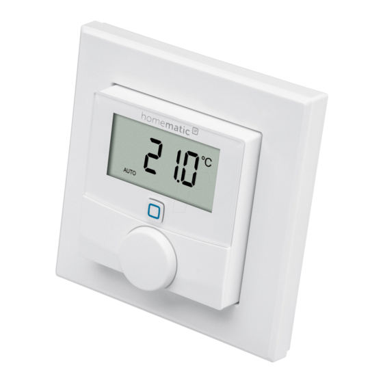
Gewährleistungs- und Haftungsausschluss. Funktion und Geräteübersicht Mit dem Homematic IP Wired Wandthermostat können Sie Ihre Fußbodenheizung in Verbindung mit Homematic IP Fußbodenheizungsaktoren zeitgesteuert regulieren und Heizphasen auf Ihre individuellen Bedürfnisse anpassen. - Page 13 Funktion und Geräteübersicht Displayübersicht (s. Abbildung 2): Soll-/Ist-Temperatur Luftfeuchtigkeit Warnung für Betauung Fenster-auf-Symbol Funkübertragung Boost-Funktion Manueller Betrieb Automatikbetrieb Urlaubsmodus Heizen Kühlen Bediensperre Soll-Temperatur Alle weiteren Symbole finden Sie im Kapitel „6 Betriebsmodi und Konfiguration“ auf Seite 26.
-
Page 14: Allgemeine Systeminformationen
Sie haben die Möglichkeit, alle Geräte des Systems komfor- tabel und individuell über die Bedienoberfläche der Zent- rale CCU3 oder flexibel per Smartphone über die Home- matic IP App in Verbindung mit der Homematic IP Cloud zu konfigurieren. Welcher Funktionsumfang sich innerhalb des Systems im Zusammenspiel mit weiteren Komponen- ten ergibt, entnehmen Sie bitte dem Homematic IP Wired... - Page 15 Inbetriebnahme Beachten Sie die auf dem Gerät angegebene Ab- isolierlänge der anzuschließenden Leiter. Beachten Sie bei der Installation die Gefahrenhin- weise gemäß „2 Gefahrenhinweise“ auf Seite 9. Hinweis! Installation nur durch Personen mit einschlägigen elektrotechnischen Kenntnissen und Erfahrungen!* Durch eine unsachgemäße Installation gefährden Sie •...
- Page 16 Zugelassene Leitungsquerschnitte zum Anschluss an den Wandthermostat sind: Starre Leitung: 0,12-0,50 mm Aus Gründen der elektrischen Sicherheit dürfen zum Anschluss des Homematic IP Wired Bus aus- schließlich folgende Leitungen eingesetzt werden: • Fernmeldeleitung J-Y(ST)Y mit 2 x 2 x 0,8 (= 0,5 mm²) oder 4 x 2 x 0,8 (= 0,5 mm²),...
-
Page 17: Installation
Inbetriebnahme Installation Der Bus wird vom Homematic IP Wired Access Point (HmIPW-DRAP) gespeist. Weitere Informa- tionen dazu können Sie der Bedienungsanleitung des Wired Access Points entnehmen. Für die Installation gehen Sie wie folgt vor: • Schließen Sie den Homematic IP Wired Bus an die Busanschlussklemmen (G) an (s. -
Page 18: Montage In Mehrfachkombinationen
Inbetriebnahme Montage in Mehrfachkombinationen Sie können den Wandthermostat sowohl mit dem mitge- lieferten Rahmen (A), als auch mit Rahmen anderer Her- steller verwenden oder die Elektronikeinheit (B) in einen Mehrfachrahmen integrieren. Bei der Montage in Mehr- fachkombinationen ist darauf zu achten, dass die Mon- tageplatte des Wandthermostats bündig neben bereits befestigte Montageplatten/Tragringen angebracht und daran ausgerichtet wird. -
Page 19: Anlernen
Sie können den Wandthermostat direkt an den Wi- red Fußbodenheizungsaktor anlernen. Die Konfigu- ration erfolgt dann direkt über den Wandthermos- tat (s. „5.4.1 Anlernen an den Homematic IP Wired Fußbodenheizungsaktor“ auf Seite 20). Anlernen an die Zentrale CCU3 Für eine lokale, softwarebasierte Konfiguration und Steu- erung per PC haben Sie die Möglichkeit, den Wandther-... -
Page 20: Anlernen An Den Homematic Ip Wired Fußbodenheizungsaktor
Wenn kein Anlernen erfolgt, wird der Anlernmo- dus automatisch nach 30 Sekunden beendet. Wenn Sie den Wandthermostat an einen Homematic IP Wired Fußbodenheizungsaktor anlernen möchten, müs- sen die beiden zu verknüpfenden Geräte in den Anlern- modus gebracht werden. Dafür gehen Sie wie folgt vor: •... -
Page 21: Anlernen An Die Zentrale Ccu3
CCU3 anzulernen, gehen Sie wie folgt vor: • Richten Sie zunächst Ihre Zentrale CCU3 gemäß der zugehörigen Bedienungsanleitung ein und ler- nen Sie den Homematic IP Wired Access Point an. • Starten Sie die Benutzeroberfläche „WebUI“ auf Ihrem PC. - Page 22 Inbetriebnahme • Klicken Sie auf den Button „Geräte anlernen“ im rechten oberen Bereich des Browserfensters. • Um den Anlernmodus zu aktivieren, klicken Sie im nächsten Fenster auf „HmIP Gerät anlernen“. Die Zentrale wird für 60 Sekunden in den Anlern- modus versetzt. Ein Infofeld zeigt die aktuell noch verbleibende Anlernzeit.
- Page 23 Weitere Informationen finden Sie im Homema- tic IP Wired Systemhandbuch unter www.eQ-3.de. Im Betrieb ohne aktiven Internetzugang wählen Sie die Option „Homematic IP Gerät ohne Inter- netzugang anlernen“. Geben Sie zum Anlernen die SGTIN und den Key des Geräts in die entspre-...
-
Page 24: Anlernen An Die Homematic Ip Cloud Per Wired Access Point
5.4.3 Anlernen an die Homematic IP Cloud per Wired Access Point Wenn Sie Ihre Homematic IP Wired Geräte flexibel per Smartphone-App steuern möchten, können Sie die Homematic IP Wired Geräte einfach an die Homematic IP Cloud anlernen. Gehen Sie dazu wie folgt vor: •... - Page 25 • Vergeben Sie in der App einen Namen für das Ge- rät und ordnen Sie es einem Raum zu. Wenn Sie bereits Homematic IP Geräte im Smart- Home-System nutzen oder Ihre Wired Geräte mit Funk-Komponenten von Homematic IP kombi- nieren möchten, können Sie die Homematic IP Wired Geräte auch einfach an einen (bestehen-...
-
Page 26: Betriebsmodi Und Konfiguration
Betriebsmodi und Konfiguration Betriebsmodi und Konfiguration Nach dem Anlernen und der Montage können Sie über das Konfigurationsmenü Einstellungen vornehmen, um das Gerät an Ihre persönlichen Bedürfnissen anzupassen. Gehen Sie dafür wie folgt vor: Drücken Sie lange auf das Stellrad (E), um das •... -
Page 27: Automatikbetrieb
Betriebsmodi und Konfiguration Konfiguration des Fußbodenheizungs- aktors 6.10 Verbindungstest Automatikbetrieb Im Automatikbetrieb erfolgt die Temperaturregelung ge- mäß des eingestellten Heizprofils (s. „6.5.3 Heizprofil“ auf Seite 34). Manuelle Änderungen über das Stellrad (E) bleiben bis zum nächsten Schaltzeitpunkt aktiv. Danach wird das eingestellte Heizprofil wieder aktiviert. Um den Automatikbetrieb zu aktivieren, gehen Sie wie folgt vor: •... -
Page 28: Urlaubsmodus
Betriebsmodi und Konfiguration Sie können das Ventil des Fußbodenheizungsak- tors vollständig schließen bzw. öffnen, indem Sie das Stellrad (E) bis zum Anschlag gegen den Uhr- zeigersinn bzw. mit dem Uhrzeigersinn drehen. Im Display wird entsprechend „OFF“ bzw. „On“ angezeigt. Urlaubsmodus Der Urlaubsmodus kann genutzt werden, wenn für einen bestimmten Zeitraum (z. -
Page 29: Bediensperre
Betriebsmodi und Konfiguration welche Räume der Urlaubsmodus aktiviert wer- den soll: Auswahl „OnE“: Urlaubsmodus wird für den aktu- ellen Wandthermostat aktiviert. Auswahl „ALL“: Urlaubsmodus wird für alle Wandthermostate, die an den Fußbodenhei- zungsaktor angelernt sind, aktiviert. Bediensperre Die Bedienung am Gerät kann gesperrt werden, um das ungewollte Verändern von Einstellungen, z. -
Page 30: Programmierung Der Heizprofile
Betriebsmodi und Konfiguration Programmierung der Heizprofile Unter diesem Menüpunkt können Sie Einstellungen für Ihre Heiz- bzw. Kühlprofile vornehmen und Heizprofile nach Ihren eigenen Bedürfnissen erstellen. • Wählen Sie durch Drehen des Stellrads das Sym- bol „ “ aus und bestätigen Sie die Auswahl durch kurzes Drücken des Stellrads. -
Page 31: Heizprofilnummer
Betriebsmodi und Konfiguration 6.5.2 Heizprofilnummer Sie können zwischen den 6 folgenden, bereits vorkonfi- gurierten Profilen wählen. • Wählen Sie im Menüpunkt „Pr.nr.“ durch Drehen des Stellrads (E) die Nummer des gewünschten Profils aus und bestätigen Sie die Auswahl durch kurzes Drücken des Stellrads. Ist das gewählte Profil ein Heizprofil, wird geheizt, sobald die Raumtemperatur unter den festgeleg- ten Wert fällt. - Page 32 Betriebsmodi und Konfiguration Samstag bis Sonntag Temp. 00:00 bis 06:00 Uhr 17,0 °C 06:00 bis 22:00 Uhr 21,0 °C 22:00 bis 23:59 Uhr 17,0 °C Profil 2 Vorkonfiguriert für Heizen per Fußbodenheizung Montag bis Freitag Temp. 00:00 bis 05:00 Uhr 19,0 °C 05:00 bis 08:00 Uhr 21,0 °C...
- Page 33 Betriebsmodi und Konfiguration Profil 4 Alternatives Kühlprofil 1 Montag bis Freitag Temp. 00:00 bis 06:00 Uhr 17,0 °C 06:00 bis 09:00 Uhr 21,0 °C 09:00 bis 17:00 Uhr 17,0 °C 17:00 bis 22:00 Uhr 21,0 °C 22:00 bis 23:59 Uhr 17,0 °C Samstag bis Sonntag Temp.
-
Page 34: Heizprofil
Betriebsmodi und Konfiguration Profil 6 Alternatives Kühlprofil 1 Montag bis Sonntag Temp. 00:00 bis 06:00 Uhr 17,0 °C 06:00 bis 22:00 Uhr 21,0 °C 22:00 bis 23:59 Uhr 17,0 °C 6.5.3 Heizprofil Im Heizprofil lassen sich für jeden Wochentag des ge- wählten Heizprofils separat bis zu 6 Heizphasen (13 Schaltzeitpunkte) individuell einstellen. -
Page 35: Optimum-Start-/Stop-Funktion
Betriebsmodi und Konfiguration bestätigen Sie die Auswahl durch kurzes Drücken des Stellrads. • Im Display wird die nächste Uhrzeit angezeigt. Sie können diese Zeit mit dem Stellrad verändern. • Wählen Sie durch Drehen des Stellrads die ge- wünschte Temperatur für den nächsten Zeitab- schnitt aus und bestätigen Sie die Auswahl durch kurzes Drücken des Stellrads. -
Page 36: Offset-Temperatur
Betriebsmodi und Konfiguration • Stellen Sie durch Drehen des Stellrads Jahr, Mo- nat, Tag und Uhrzeit ein und bestätigen Sie durch kurzes Drücken des Stellrads. Offset-Temperatur Da die Temperatur am Wandthermostaten gemessen wird, kann es an einer anderen Stelle im Raum kälter oder wärmer sein. -
Page 37: Konfiguration Des Fußbodenheizungsaktors
Sie Ihre Auswahl durch kurzes Drücken des Stellrads. Konfiguration des Fußbodenheizungsaktors Unter diesem Menüpunkt können Sie Einstellungen für Ihren Homematic IP Wired Fußbodenheizungsaktor vor- nehmen. • Wählen Sie durch Drehen des Stellrads das Sym- bol „... -
Page 38: Verbindungstest
Homematic IP Wired Fußbodenheizungsaktors. 6.10 Verbindungstest Sie können die Verbindung zwischen Ihrem Homema- tic IP Wired Wandthermostat und dem Homematic IP Wi- red Fußbodenheizungsaktor überprüfen. Bei dieser Über- prüfung sendet der Wandthermostat einen Schaltbefehl an den Fußbodenheizungsaktor und je nachdem in wel- chem Schaltzustand sich der Aktor befindet, schaltet er sich nach Erhalt des Befehls zur Bestätigung ein bzw. -
Page 39: Fehlercodes Und Blinkfolgen
Fehlercodes und Blinkfolgen verändern. Im Automatikbetrieb bleibt die ma- nuell eingestellte Temperatur bis zum nächsten Schaltzeitpunkt bestehen. Danach wird das ein- gestellte Heizprofil wieder aktiviert. Im manuellen Betrieb bleibt die Temperatur bis zur nächsten manuellen Änderung erhalten. Fehlercodes und Blinkfolgen Fehler- und Bedeutung Lösung... - Page 40 Fehlercodes und Blinkfolgen Kurzes Datenübertra- Warten Sie, bis oranges gung die Übertragung Blinken beendet ist. 1x langes Vorgang Sie können mit grünes bestätigt der Bedienung Leuchten fortfahren. 1x langes rotes Vorgang Versuchen Sie es Leuchten fehlgeschlagen erneut. Kurzes Anlernmodus Geben Sie die oranges aktiv letzten vier Ziffern...
-
Page 41: Wiederherstellung Der Werkseinstellungen
Lassen Sie die Systemtaste wieder los, um das Wiederherstellen der Werkseinstellungen abzu- schließen. Das Gerät führt einen Neustart durch. Nach dem Neustart können Sie das Gerät wieder in Ihr Homematic IP System integrieren. Wartung und Reinigung Das Gerät ist wartungsfrei. Überlassen Sie eine... -
Page 42: Technische Daten
Reinigen Sie das Gerät mit einem weichen, sauberen, trockenen und fusselfreien Tuch. Verwenden Sie keine lösemittelhaltigen Reinigungsmittel, das Kunststoffge- häuse und die Beschriftung können dadurch angegriffen werden. Technische Daten Geräte-Kurzbezeichnung: HmIPW-WTH Versorgungsspannung: 24 V , +5 % -20 %, SELV Stromaufnahme: 20 mA max. Leitungsart u. -querschnitt: Starre Leitung 0,12-0,50 mm²... - Page 43 Technische Daten prüfung: 850 °C Temperatur Kugeldruck- prüfung: 125 °C PTI-Wert des Gehäuse- materials: IIIb mit 100 < CTI < 175 Technische Änderungen vorbehalten. Entsorgungshinweis Gerät nicht im Hausmüll entsorgen! Elektroni- sche Geräte sind entsprechend der Richtlinie über Elektro- und Elektronik-Altgeräte über die örtlichen Sammelstellen für Elektronik-Altgeräte zu entsorgen.
- Page 44 Package contents Quantity Description Homematic IP Wired Wall Thermostat with Humidity Sensor Clip-on frame Mounting plate Screws 3.2 x 15 mm Screws 3.2 x 25 mm User manual Documentation © 2018 eQ-3 AG, Germany. All rights reserved. Translation from the original version in Ger- man.
- Page 45 Installation instructions ............. 52 Installation ................55 Installation in multiple combinations ......55 Teaching-in ................56 5.4.1 Pairing with a Homematic IP Floor Heating Actu- ator ................58 5.4.2 Connecting to the CCU3 ........59 5.4.3 Connecting to the Homematic IP cloud via Wired Access Point ..........61...
- Page 46 Selecting the desired temperature display .....72 Configuring the floor heating actuator ......73 6.10 Communication test ............73 Operation .................74 Error codes and flashing sequences ......75 Restore factory settings ..........76 10 Maintenance and cleaning ........... 77 Technical specifications ..........77...
-
Page 47: Information About This Manual
Information about this manual Information about this manual Please read this manual carefully before beginning op- eration with your Homematic IP Wired component. Keep the manual so you can refer to it at a later date if you need to. - Page 48 Hazard information Do not use the device if there are signs of dam- age to the housing, control elements or connect- ing sockets, for example. If you have any doubts, have the device checked by an expert. The device may only be operated in dry and dust- free environment and must be protected from the effects of moisture, vibrations, solar or other methods of heat radiation, cold and mechanical...
- Page 49 The device is intended for operation within the Homematic IP Wired bus only. The Homematic IP Wired bus is a SELV power circuit. Common cable routing for power supply and the Homematic IP Wired bus in installation or junction boxes is not permitted.
-
Page 50: Function And Device Overview
Function and device overview The Homematic IP Wired Wall Thermostat offers time- controlled regulation of floor heating systems in connec- tion with Homematic IP Floor Heating Actuators accord- ing to individually tailored heating phases. - Page 51 Function and device overview Display overview (see figure 2): Set/actual temperature Humidity Warning about condensation Open window symbol Radio transmission Boost function Manual operation Automatic mode Holiday mode Heating Cooling Operating lock Setpoint temperature You will find a description of all symbols in section „6 Operating modes and configuration“...
-
Page 52: General System Information
General system information General system information This device is part of the Homematic IP smart home system and works with the Homematic IP protocol. All devices of the system can be configured comfortably and individually with the user interface of the Central Control Unit CCU3 or flexibly via the Homematic ... - Page 53 Start-up Please note the insulation stripping length of the conductor to be connected, indicated on the de- vice. Please observe the hazard information in section „2 Hazard information“ on page 47 during in- stallation. Please note! Only to be installed by persons with the relevant electro-technical knowledge and experience!* Incorrect installation can put...
- Page 54 Start-up sary, personal safety equipment; • Evaluation of measuring results; • Selection of electrical installation material for safeguard- ing shut-off conditions; • IP protection types; • Installation of electrical installation material; • Type of supply network (TN system, IT system, TT sys- tem) and the resulting connecting conditions (classical zero balancing, protective earthing, required additional measures etc.).
-
Page 55: Installation
Start-up Installation The bus is supplied by the Homematic IP Wired Access Point (HmIPW-DRAP). For further infor- mation, please refer to the operating manual of the Wired Access Point. For the installation, please proceed as follows: • Connect the Homematic IP Wired bus to the bus connecting terminals (G) (see fig. -
Page 56: Teaching-In
Start-up wall thermostat is seamlessly aligned to the already fixed mounting plate/retaining ring. Frames of the following manufacturers can be used: Manufacturer Frame Berker S.1, B.1, B.3, B.7 Busch Jaeger carat*, future linear*, solo*, Busch- axcent*, Busch-dynasty*, balance SI ELSO GIRA Standard 55, E2, E22, Event, Esprit, ClassiX, E3... - Page 57 Connecting to the Homematic IP cloud For flexible control via the free smartphone app, you can connect the wall thermostat to the Homematic IP cloud (see „5.4.3 Connecting to the Homematic IP cloud via Wired Access Point“ on page 61). You can •...
-
Page 58: Pairing With A Homematic Ip Floor Heating Actuator
If no teach-in operations are carried out, teach-in mode is exited automatically after 30 seconds. If you want to pair the wall thermostat with a Homematic IP Wired Floor Heating Actuator, the pairing mode of both devices has to be activated first. To do this, proceed as follows: •... -
Page 59: Connecting To The Ccu3
CCU3, proceed as follows: • Set up your Central Control Unit CCU3 as de- scribed in the operating manual and connect the Homematic IP Wired Access Point. • Start the user interface WebUI on your computer. • Click the “Teach-in devices” button on the right- hand side of the screen. - Page 60 Start-up • After establishing the power supply, the teach-in mode of the wall thermostat remains activated for 3 minutes. You can manually start the teach-in mode for an- other 3 minutes by pressing the system button (D) briefly (see figure 8). •...
-
Page 61: Connecting To The Homematic Ip Cloud Via Wired Access Point
5.4.3 Connecting to the Homematic IP cloud via Wired Access Point If you want to control your Homematic IP Wired devices flexibly via smartphone app, they can be connected to the Homematic IP cloud. To do this, please proceed as follows: •... - Page 62 In the app, give the device a name and allocate it to a room. If you are already using Homematic IP devices in your smart home system or if you want to com- bine your Homematic IP Wired devices with wire-...
-
Page 63: Operating Modes And Configuration
Operating modes and configuration Operating modes and configuration After teaching-in and mounting the device, you can in- dividually adjust the settings to your personal needs via the configuration menu. To do this, proceed as follows: • Press and hold down the control wheel (E) to open the configuration menu. -
Page 64: Automatic Mode
Operating modes and configuration Automatic mode In automatic mode, the temperature is controlled in ac- cordance with the set heating profile (see „6.5.3 Heating profile“ on page 70). Manual changes that are set via the control wheel (E) are activated until the next point at which the profile changes. -
Page 65: Holiday Mode
Operating modes and configuration Holiday mode The holiday mode can be used if you want to maintain a fixed temperature for a certain period (e.g. during your holidays or a party). To activate the holiday mode, please proceed as follows: •... -
Page 66: Programming Of Heating Profiles
Operating modes and configuration touch). To activate the operating lock, please proceed as follows: • Select the symbol by turning the control wheel and confirm by pressing the control wheel briefly. • Turn the control wheel to select “On” in order to activate the operating lock or “OFF”... -
Page 67: Heating Or Cooling
Operating modes and configuration (”OFF”) the optimum start/stop function. 6.5.1 Heating or cooling You can use your floor heating system to heat rooms dur- ing winter or to cool rooms during summer. • Select “HEAT” for heating and “COOL” for cool- ing in the menu item “type”... - Page 68 Operating modes and configuration Profile 1: Pre-configured heating via radiator thermostat Monday to Friday Temp. 00:00 - 06:00 17.0 °C 06:00 - 09:00 21.0 °C 09:00 - 17:00 17.0 °C 17:00 - 22:00 21.0 °C 22:00 - 23:59 17.0 °C Saturday to Sunday Temp.
- Page 69 Operating modes and configuration Profile 3: Alternative profile Monday to Sunday Temp. 00:00 - 06:00 17.0 °C 06:00 - 22:00 21.0 °C 22:00 - 23:59 17.0 °C Profile 4: Alternative cooling profile 1 Monday to Friday Temp. 00:00 - 06:00 17.0 °C 06:00 - 09:00 21.0 °C...
-
Page 70: Heating Profile
Operating modes and configuration Saturday to Sunday Temp. 00:00 - 06:00 23.0 °C 06:00 - 23:00 21.0 °C 23:00 - 23:59 23.0 °C Profile 6: Alternative cooling profile 1 Monday to Sunday Temp. 00:00 - 06:00 17.0 °C 06:00 - 22:00 21.0 °C 22:00 - 23:59 17.0 °C... -
Page 71: Optimum Start/Stop Function
Operating modes and configuration • Select the desired temperature for the start time by turning the control wheel and confirm by pressing the control wheel briefly. • The next time is shown in the display. You can change this time using the control wheel. •... -
Page 72: Offset Temperature
Operating modes and configuration Offset temperature As the temperature is measured on the wall thermostat, the temperature distribution can vary throughout a room. To adjust this, a temperature offset of ±3.5 °C can be set. If a nominal temperature of e.g. 20 °C is set but the room presents with only 18 °C, an offset of -2.0 °C needs to be set. -
Page 73: Configuring The Floor Heating Actuator
6.10 Communication test You can check the connection between your Homematic IP Wired Wall Thermostat and the Homematic IP Wired Floor Heating Actuator. During this test, the wall thermo- stat transmits a switching command to the floor heating actuator. Depending on the current status of the actua-... -
Page 74: Operation
Operation receiving the command. • Select the symbol by turning the control wheel and confirm by pressing the control wheel briefly. The connection test is carried out. Operation After configuration, simple operations are available di- rectly on the device. If the wall thermostat is in standby mode, please press the control wheel (E) once before operation to activate the device. -
Page 75: Error Codes And Flashing Sequences
Error codes and flashing sequences Error codes and flashing sequences Error and Meaning Solution flashing codes Antenna Communica- Check the con- symbol flash- tion error to nection to the ing ( ) CCU/ CCU/ to floor heating floor heating actuator actuator. -
Page 76: Restore Factory Settings
Restore factory settings Short orange Teach-in mode Please enter the flashing active last four numbers (every 10 of the device seconds) serial number for confirmation (see „5.4 Teaching-in“ on page 56). 6x long red Device defec- Please see your flashing tive app for error mes- sage or contact... -
Page 77: Maintenance And Cleaning
• Release the system button to finish the proce- dure. The device will perform a restart. After the restart, you can again integrate your device into your Homematic IP system. Maintenance and cleaning The product does not require any maintenance. - Page 78 Technical specifications Degree of protection: IP20 Protection class: Ambient temperature: 0 to 50 °C Dimensions (W x H x D): Without frame: 71 x 71 x 42 mm Including frame: 86 x 86 x 42 mm Weight: 87 g Method of operation: Type 1 Degree of pollution: Software class:...
- Page 79 Technical specifications Instructions for disposal Do not dispose of the device with regular domes- tic waste! Electronic equipment must be dis- posed of at local collection points for waste elec- tronic equipment in compliance with the Waste Electrical and Electronic Equipment Directive. Information about conformity The CE sign is a free trading sign addressed ex- clusively to the authorities and does not include...
- Page 80 Kostenloser Download der Homematic IP App! Free download of the Homematic IP app! Bevollmächtigter des Herstellers: Manufacturer’s authorised representative: eQ-3 AG Maiburger Straße 29 26789 Leer / GERMANY www.eQ-3.de...
Need help?
Do you have a question about the HmIPW-WTH and is the answer not in the manual?
Questions and answers