Table of Contents
Advertisement
Available languages
Available languages
Quick Links
Advertisement
Chapters
Table of Contents

Related Manuals for HomeMatic HmIP-BWTH24


Summary of Contents for HomeMatic HmIP-BWTH24
- Page 1 Installations- und Bedienungsanleitung Installation instruction and operating manual Wandthermostat mit Schaltausgang – S. 2 für Markenschalter, 24 V Wall Thermostat with switching p. 47 output – for brand switches, 24 V HmIP-BWTH24...
- Page 2 Lieferumfang Anzahl Bezeichnung Homematic IP Wandthermostat mit Schaltausgang – für Markenschalter, 24 V Wechselrahmen Spannungsversorgungseinheit Schrauben 3,2 x 15 mm Schrauben 3,2 x 25 mm Bedienungsanleitung Dokumentation © 2017 eQ-3 AG, Deutschland Alle Rechte vorbehalten. Ohne schriftliche Zustimmung des Herausgebers darf diese Anleitung auch nicht auszugsweise in...
-
Page 7: Table Of Contents
Netzspannung ................18 Anlernen ................19 5.4.1 Anlernen an den Homematic IP Fußbodenheizungsaktor ........19 5.4.2 Anlernen an den Homematic IP Access Point ..21 Betriebsmodi und Konfiguration .........22 Automatikbetrieb ..............23 Manueller Betrieb..............24 Urlaubsmodus ..............25 Bediensperre ................ 26 Antriebstyp und häusliche Gegebenheiten ................27... - Page 8 Offset-Temperatur .............. 35 Auswahl der gewünschten Temperaturanzeige ... 35 6.10 Konfiguration des Fußbodenheizungsaktors ....36 6.11 Verbindungstest ..............37 Bedienung ................37 Fehlerbehebung .............38 Befehl nicht bestätigt ............38 Duty Cycle ................39 Fehlercodes und Blinkfolgen ........... 40 Wiederherstellung der Werkseinstellungen ....42 10 Wartung und Reinigung ..........43 Allgemeine Hinweise zum Funkbetrieb .....43 12 Technische Daten ............
-
Page 9: Hinweise Zur Anleitung
Hinweise zur Anleitung Hinweise zur Anleitung Lesen Sie diese Anleitung sorgfältig, bevor Sie Ihre Homematic IP Geräte in Betrieb nehmen. Bewahren Sie die Anleitung zum späteren Nachschlagen auf! Wenn Sie das Gerät anderen Personen zur Nutzung über- lassen, übergeben Sie auch diese Anleitung. - Page 10 Gefahrenhinweise Betreiben Sie das Gerät nur in trockener sowie staubfreier Umgebung, setzen Sie es keinem Ein- fluss von Feuchtigkeit, Vibrationen, ständiger Sonnen- oder anderer Wärmeeinstrahlung, Kälte und keinen mechanischen Belastungen aus. Das Gerät ist kein Spielzeug! Erlauben Sie Kindern nicht damit zu spielen. Lassen Sie das Verpa- ckungsmaterial nicht achtlos liegen.
- Page 11 Gefahrenhinweise Beachten Sie vor Anschluss eines Verbrauchers die technischen Daten, insbesondere die maximal zulässige Anschlussleistung und Art des anzu- schließenden Verbrauchers. Alle Lastangaben be- ziehen sich auf ohmsche Lasten. Belasten Sie den Aktor nur bis zur angegebenen Leistungsgrenze. Eine Überlastung kann zur Zerstörung des Gerä- tes, zu einem Brand oder zu einem elektrischen Schlag führen.
-
Page 12: Funktion Und Geräteübersicht
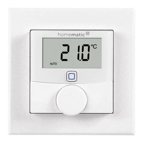
Der Wandthermostat misst die Temperatur und Luft- feuchtigkeit im Raum und steuert auf Basis der aktuellen Werte den Triac-Ausgang. Die Steuerung und Konfigurati- on kann direkt am Homematic IP Wandthermostaten oder alternativ bequem über die kostenlose Homematic IP App erfolgen. Sie können den bereits vorhandenen Wandthermostaten Ihrer bestehenden Installation einfach gegen den Home- matic IP Wandthermostaten austauschen und das Gerät in... - Page 13 Funktion und Geräteübersicht lungen wird der Installationsaufwand auf ein Minimum reduziert. Das Design bzw. Farben und Oberflächen von bereits installierten Schalterserien bleiben unverändert, da vorhandene Rahmen weiter genutzt werden können. Geräteübersicht (s. Abbildung 1): Wechselrahmen Elektronikeinheit (Thermostat) Display Systemtaste (Anlerntaste und LED) Stellrad Spannungseinheit Displayübersicht (s.
-
Page 14: Allgemeine Systeminformationen
Alle weiteren Symbole finden Sie im Kapitel „6 Betriebsmodi und Konfiguration“ auf Seite 22. Allgemeine Systeminformationen Dieses Gerät ist Teil des Homematic IP Smart-Home- Systems und kommuniziert über das Homematic IP Funkprotokoll. Alle Geräte des Systems können komfor- tabel und individuell per Smartphone über die Homema- tic ... -
Page 15: Inbetriebnahme
Inbetriebnahme teren Komponenten ergibt, entnehmen Sie bitte dem Homematic IP Anwenderhandbuch. Alle technischen Dokumente und Updates finden Sie stets aktuell unter www.eQ-3.de. Inbetriebnahme Installationshinweise Bitte lesen Sie diesen Abschnitt erst vollständig, bevor Sie mit der Installation beginnen. Bitte notieren Sie sich vor der Installation die auf dem Gerät angebrachte Gerätenummer (SGTIN) - Page 16 Inbetriebnahme Mit einer unsachgemäßen Installation riskieren Sie schwere Sachschäden, z. B. durch Brand. Es droht für Sie die persönliche Haftung bei Personen- und Sachschäden. Wenden Sie sich an einen Elektroinstallateur! Erforderliche Fachkenntnisse für die Installation: Für die Installation sind insbesondere folgende Fachkenntnisse erforder- lich: •...
-
Page 17: Installation
Inbetriebnahme Zugelassene Leitungsquerschnitte zum Anschluss an den Wandthermostaten sind: Starre Leitung Flexible Leitung mit und ohne Aderendhülse [mm 0,75 – 1,50 0,75 – 1,50 Installation Für die Installation des Wandthermostats gehen Sie wie folgt vor: • Schalten Sie die Haussicherung des Stromkreises •... -
Page 18: Verhalten Nach Einschalten Der Netzspannung
Inbetriebnahme Setzen Sie die Spannungseinheit (F) in die Unter- • putzdose ein und befestigen Sie ihn mittels der mitgelieferten Schrauben an der Unterputzdose. • Setzen Sie den Rahmen Ihrer Installation oder den mitgelieferten Wechselrahmen (A) auf die Spannungseinheit auf. Setzen Sie die Elektronikeinheit (B) des Wand- •... -
Page 19: Anlernen
Sie können den Wandthermostaten zur Steuerung Ihrer Fußbodenheizung entweder direkt an den Homematic IP Fußbodenheizungsaktor oder zur Steuerung des gesam- ten Raumklimas an den Homematic IP Access Point an- lernen. Beim direkten Anlernen erfolgt die Konfiguration am Gerät und beim Anlernen an den Access Point über die Homematic IP App. - Page 20 Inbetriebnahme Sie können den Anlernvorgang durch erneute kurze Betätigung der Systemtaste (D) abbrechen. Dies wird durch rotes Aufleuchten der Geräte- LED (D) bestätigt. Wenn kein Anlernen erfolgt, wird der Anlernmo- dus automatisch nach 30 Sekunden beendet. Wenn Sie den Wandthermostaten an einen Homema- tic ...
-
Page 21: Anlernen An Den Homematic Ip Access Point
5.4.2 Anlernen an den Homematic IP Access Point Richten Sie zunächst Ihren Homematic IP Access Point über die Homematic IP App ein, um weitere Homematic IP Geräte im System nutzen zu kön- nen. Ausführliche Informationen dazu finden Sie in der Bedienungsanleitung des Access Points. -
Page 22: Betriebsmodi Und Konfiguration
Betriebsmodi und Konfiguration ist. • Zur Bestätigung eines erfolgreichen Anlernvor- gangs leuchtet die LED (D) grün. Das Gerät ist nun einsatzbereit. • Leuchtet die LED (D) rot, versuchen Sie es erneut. • Ordnen Sie das Gerät in der App einem Raum zu und vergeben Sie einen Namen für das Gerät. -
Page 23: Automatikbetrieb
Betriebsmodi und Konfiguration Automatikbetrieb Manueller Betrieb Urlaubsmodus Bediensperre Antriebstyp und häusliche Gegeben- heiten Programmierung der Heizprofile Datum und Uhrzeit Offset-Temperatur Auswahl der gewünschten Tempera- turanzeige 6.10 Konfiguration des Fußbodenheizungs- aktors 6.11 Verbindungstest Automatikbetrieb Im Automatikbetrieb erfolgt die Temperaturregelung gemäß dem eingestellten Wochenprofil (s. „6.6.3 Wo- chenprofil“... -
Page 24: Manueller Betrieb
Betriebsmodi und Konfiguration aktiv. Danach wird das eingestellte Wochenprofil wieder aktiviert. Um den Automatikbetrieb zu aktivieren, gehen Sie wie folgt vor: Drücken Sie lange auf das Stellrad (E), um das • Konfigurationsmenü zu öffnen (s. Abbildung 6). • Wählen Sie durch Drehen des Stellrads das Sym- bol „... -
Page 25: Urlaubsmodus
Betriebsmodi und Konfiguration Urlaubsmodus Der Urlaubsmodus kann genutzt werden, wenn für einen bestimmten Zeitraum (z. B. während eines Urlaubs oder ei- ner Party) eine feste Temperatur gehalten werden soll. Um den Urlaubsmodus einzustellen, gehen Sie wie folgt vor: Drücken Sie lange auf das Stellrad (E), um das •... -
Page 26: Bediensperre
Betriebsmodi und Konfiguration Auswahl „ALL“ (Nur in Verbindung mit einem Fußbodenheizungsaktor relevant): Der Urlaubsmodus wird für alle Wandther- mostate, die an den Fußbodenheizungsaktor angelernt sind, aktiviert. Bediensperre Die Bedienung am Gerät kann gesperrt werden, um das ungewollte Verändern von Einstellungen, z. B. durch ver- sehentliches Berühren, zu verhindern. -
Page 27: Antriebstyp Und Häusliche Gegebenheiten
Betriebsmodi und Konfiguration Antriebstyp und häusliche Gegebenheiten Unter diesem Menüpunkt können Sie den Antriebstyp (normally closed oder normally open), der am Schaltaus- gang angeschlossen wird und die häuslichen Gegeben- heiten auswählen. Drücken Sie lange auf das Stellrad (E), um das •... -
Page 28: Programmierung Der Wochenprofile
Betriebsmodi und Konfiguration Programmierung der Wochenprofile Unter diesem Menüpunkt können Sie Einstellungen für Ihre Heiz- bzw. Kühlprofile vornehmen und Wochenpro- file nach Ihren eigenen Bedürfnissen erstellen. • Drücken Sie lange auf das Stellrad (E), um das Konfigurationsmenü zu öffnen (s. Abbildung 6). •... -
Page 29: Wochenprofilnummer
Betriebsmodi und Konfiguration 6.6.2 Wochenprofilnummer Sie können zwischen den 6 folgenden, bereits vorkonfi- gurierten Profilen wählen. • Wählen Sie im Menüpunkt „Pr.nr.“ durch Drehen des Stellrads (E) die Nummer des gewünschten Profils aus und bestätigen Sie die Auswahl durch kurzes Drücken des Stellrads. Ist das gewählte Profil ein Heizprofil, wird geheizt, sobald die Raumtemperatur unter den festgeleg- ten Wert fällt. - Page 30 Betriebsmodi und Konfiguration Samstag bis Sonntag Temp. 00:00 bis 06:00 Uhr 17,0 °C 06:00 bis 22:00 Uhr 21,0 °C 22:00 bis 23:59 Uhr 17,0 °C Profil 2 Vorkonfiguriert für Heizen per Fußbodenheizung Montag bis Freitag Temp. 00:00 bis 05:00 Uhr 19,0 °C 05:00 bis 08:00 Uhr 21,0 °C...
- Page 31 Betriebsmodi und Konfiguration Profil 3 Alternatives Heizprofil Montag bis Sonntag Temp. 00:00 bis 06:00 Uhr 17,0 °C 06:00 bis 22:00 Uhr 21,0 °C 22:00 bis 23:59 Uhr 17,0 °C Profil 4 Alternatives Kühlprofil 1 Montag bis Freitag Temp. 00:00 bis 06:00 Uhr 17,0 °C 06:00 bis 09:00 Uhr 21,0 °C...
- Page 32 Betriebsmodi und Konfiguration Profil 5 Vorkonfiguriert für Kühlen per Fußbodenheizung Montag bis Freitag Temp. 00:00 bis 05:00 Uhr 23,0 °C 05:00 bis 08:00 Uhr 21,0 °C 08:00 bis 15:00 Uhr 23,0 °C 15:00 bis 22:00 Uhr 21,0 °C 22:00 bis 23:59 Uhr 23,0 °C Samstag bis Sonntag Temp.
-
Page 33: Wochenprofil
Betriebsmodi und Konfiguration 6.6.3 Wochenprofil Im Wochenprofil lassen sich für jeden Wochentag des gewählten Heiz- bzw. Kühlprofils separat bis zu 6 Heiz- phasen (13 Schaltzeitpunkte) individuell einstellen. Die Programmierung erfolgt für die ausgewählten Tage, wo- bei für einen Zeitraum von 00:00 bis 23:59 Uhr Tempera- turen hinterlegt werden können. -
Page 34: Optimum-Start-/Stop-Funktion
Betriebsmodi und Konfiguration • Wiederholen Sie diesen Vorgang, bis für den ge- samten Zeitraum von 0:00 bis 23:59 Uhr Tempe- raturen hinterlegt sind. 6.6.4 Optimum-Start-/Stop-Funktion Damit zur festgelegten Zeit die gewünschte Temperatur im Raum bereits erreicht wurde, können Sie die Opti- mum-Start-/Stop-Funktion aktivieren. -
Page 35: Offset-Temperatur
Betriebsmodi und Konfiguration Offset-Temperatur Da die Temperatur am Wandthermostaten gemessen wird, kann es an einer anderen Stelle im Raum kälter oder wärmer sein. Um dies anzugleichen, kann eine Offset- Temperatur von ±3.5 °C eingestellt werden. Werden z. B. 18 °C anstatt eingestellter 20 °C gemessen, ist ein Offset von -2.0 °C einzustellen. -
Page 36: Konfiguration Des Fußbodenheizungsaktors
Sie Ihre Auswahl durch kurzes Drücken des Stellrads. 6.10 Konfiguration des Fußbodenheizungs- aktors Unter diesem Menüpunkt können Sie Einstellungen für Ihren Homematic IP Fußbodenheizungsaktor vorneh- men. • Drücken Sie lange auf das Stellrad (E), um das Konfigurationsmenü zu öffnen (s. Abbildung 6). •... -
Page 37: Verbindungstest
Homematic IP Fußbodenheizungsaktors. 6.11 Verbindungstest Sie können die Verbindung zwischen Ihrem Homema- tic IP Wandthermostaten und dem Homematic IP Fuß- bodenheizungsaktor überprüfen. Bei dieser Überprüfung sendet der Wandthermostat einen Schaltbefehl an den Fußbodenheizungsaktor und je nachdem in welchem Schaltzustand sich der Aktor befindet, schaltet er sich nach Erhalt des Befehls zur Bestätigung ein bzw. -
Page 38: Fehlerbehebung
Danach wird das eingestellte Wochenprofil wieder aktiviert. Im manuellen Betrieb bleibt die Temperatur bis zur nächsten manuellen Ände- rung erhalten. • Boost-Funktion für Homematic IP Heizkör- perthermostate * : Drücken Stellrad (E) des Wandthermostats kurz, um die Boost- Funktion für schnelles, kurzzeitiges Aufhei- zen des Heizkörpers durch Öffnung des Ven-... -
Page 39: Duty Cycle
Erreichen des 1 %-Limits nicht mehr senden, bis diese zeitliche Begrenzung vorüber ist. Gemäß dieser Richtlinie, werden Homematic IP Geräte zu 100 % nor- menkonform entwickelt und produziert. Im normalen Betrieb wird der Duty Cycle in der Regel nicht erreicht. -
Page 40: Fehlercodes Und Blinkfolgen
Fehlercodes und Blinkfolgen Fehler- und Bedeutung Lösung Blinkcode Antennen- Kommunika- Prüfen Sie die symbol blinkt tionsstörung Verbindung zum zum Home- Homematic IP matic IP Access Access Point/Fuß- Point/Fußbo- bodenheizungs- denheizungs- aktor. aktor Spannungs- Stellen Sie die Batterie- symbol ( ) - Page 41 Fehlerbehebung 1x langes Vorgang Sie können mit grünes bestätigt der Bedienung Leuchten fortfahren. 1x langes rotes Vorgang Versuchen Sie es Leuchten fehlgeschlagen erneut (s. „8.1 Be- fehl nicht bestätigt“ auf Seite 38). Kurzes oran- Anlernmodus Geben Sie die ges Blinken aktiv letzten vier Ziffern (alle 10 s)
-
Page 42: Wiederherstellung Der Werkseinstellungen
Wiederherstellung der Werkseinstellungen Wiederherstellung der Werkseinstellungen Die Werkseinstellungen des Gerätes können wie- derhergestellt werden. Dabei gehen alle Einstel- lungen verloren. Um die Werkseinstellungen des Wandthermostats wie- derherzustellen, gehen Sie wie folgt vor: • Ziehen Sie die Elektronikeinheit (B) nach vorne ab (s. -
Page 43: Wartung Und Reinigung
Wartung und Reinigung Wartung und Reinigung Das Gerät ist für Sie bis auf einen eventuell erfor- derlichen Batteriewechsel wartungsfrei. Überlassen Sie eine Wartung oder Reparatur einer Fachkraft. Reinigen Sie das Gerät mit einem weichen, sauberen, trockenen und fusselfreien Tuch. Für die Entfernung von stärkeren Verschmutzungen kann das Tuch leicht mit lauwarmem Wasser angefeuchtet werden. -
Page 44: Technische Daten
Technische Daten Hiermit erklärt die eQ-3 AG, Maiburger Str. 29, 26789 Leer, Deutschland, dass der Funkanlagentyp Homematic IP HmIP-BWTH24 der Richtlinie 2014/53/EU entspricht. Der vollständige Text der EU-Konformitätserklärung ist unter der folgenden Internetadresse verfügbar: www.eq-3.de Technische Daten Geräte-Kurzbezeichnung: HmIP-BWTH24 Versorgungsspannung:... - Page 45 Technische Daten Maximale Funk-Sendeleistung: 10 dBm Empfängerkategorie: SRD category 2 Typ. Funk-Freifeldreichweite: 160 m Duty Cycle: < 1 % pro h/< 10 % pro h Wirkungsweise: Typ 1.B Verschmutzungsgrad: Temperatur der Kugeldruckprüfung: 125 °C Stehstoßspannung: 800 V Konstruktion des Regel- und Steuergerätes (RS): Unabhängig montiertes elektronisches RS...
- Page 46 Technische Daten Entsorgungshinweis Gerät nicht im Hausmüll entsorgen! Elektroni- sche Geräte sind entsprechend der Richtlinie über Elektro- und Elektronik-Altgeräte über die örtlichen Sammelstellen für Elektronik-Altgeräte zu entsorgen. Konformitätshinweis Das CE-Zeichen ist ein Freiverkehrszeichen, das sich ausschließlich an die Behörden wendet und keine Zusicherung von Eigenschaften beinhaltet.
-
Page 47: Package Contents
Package contents Quantity Description Homematic IP Wall Thermostat with switching output – for brand switches, 24 V Clip-on frame Voltage supply unit Screws 3.2 x 15 mm Screws 3.2 x 25 mm Operating manual Documentation © 2017 eQ-3 AG, Germany All rights reserved. - Page 48 Installation instructions ............. 56 Installation ................58 Behaviour after switching on the mains voltage ..59 Teaching-in ................59 5.4.1 Pairing with a Homematic IP Floor Heating Actuator ............ 60 5.4.2 Teaching-in to the Homematic IP Access Point .............61 Operating modes and configuration ......62 Automatic mode ..............
- Page 49 Selecting the desired temperature display .....75 6.10 Configuring the floor heating actuator ......76 6.11 Communication test ............76 Operation ................. 77 Troubleshooting .............78 Command not confirmed ..........78 Duty cycle ................79 Error codes and flashing sequences ......80 Restore factory settings ..........82 10 Maintenance and cleaning ...........82 General information about radio operation .....83 12 Technical specifications ..........
-
Page 50: Information About This Manual
Information about this manual Please read this manual carefully before beginning op- eration with your Homematic IP components. Keep the manual so you can refer to it at a later date if you need to. If you hand over the device to other persons for use, please hand over this manual as well. - Page 51 Hazard information The device may only be operated in dry and dust- free environment and must be protected from the effects of moisture, vibrations, solar or other methods of heat radiation, cold and mechanical loads. The device is not a toy; do not allow children to play with it.
- Page 52 Hazard information Please take the technical data (in particular the maximum permissible switching capacity and the type of load to be connected) into account be- fore connecting a load! All load data relates to ohmic loads. Do not exceed the capacity specified for the device.
-
Page 53: Function And Device Overview
Controlling commands and configura- tion can be realised directly on the Homematic IP Wall Thermostat or comfortably via the free Homematic IP app. You can simply replace the existing wall thermostat of your installation by the Homematic IP Wall Thermostat and install the device in the flush-mounting box. - Page 54 Function and device overview Device overview (see figure 1): Clip-on frame Electronic unit (thermostat) Display System button (teach-in button and LED) Control wheel Voltage supply unit Display overview (see figure 2): Set/actual temperature Humidity Warning about condensation Open window symbol Power supply Radio transmission Boost function...
-
Page 55: General System Information
„6 Operating modes and configuration“ on page 62. General system information This device is part of the Homematic IP smart home sys- tem and works with the Homematic IP radio protocol. All devices of the system can be configured comfortably and individually with the Homematic IP smartphone app. -
Page 56: Start-Up
Start-up Start-up Installation instructions Please read this entire section before starting to install the device. Before installation, please note the device num- ber (SGTIN) labelled on the device as well as the exact installation location in order to make later allocation easier. - Page 57 Start-up • The “5 safety rules” to be used: Disconnect from mains; Safeguard from switching on again; Check that system is deenergised; Earth and short circuit; Cover or cordon off neighbouring live parts; • Select suitable tool, measuring equipment and, if neces- sary, personal safety equipment;...
-
Page 58: Installation
Start-up Installation To install the wall thermostat, please proceed as follows: • Switch off the fuse of the power circuit. • Remove the cover of your existing wall thermo- stat. To make removal easier, a flat, pointed object such as a slotted screwdriver can be used. •... -
Page 59: Behaviour After Switching On The Mains Voltage
After 20 minutes, the triac is operated via PI control with PWM output (normal operation). If the wall thermostat is operated stand-alone (without further Homematic IP components), please continue to chapter 6. Teaching-in Please read this entire section before starting the teach-in procedure. -
Page 60: Pairing With A Homematic Ip Floor Heating Actuator
You can either pair the wall thermostat directly with the Homematic IP Floor Heating Actuator for controlling your floor heating system or teach it in to the Homematic IP Access Point for controlling the room climate in every room. After pairing, configuration has to be done directly on the device. -
Page 61: Teaching-In To The Homematic Ip Access Point
5.4.2 Teaching-in to the Homematic IP Access Point First set up your Homematic IP Access Point via the Homematic IP app to enable operation of other Homematic IP devices within your system. For further information, please refer to the oper- ating manual of the Access Point. -
Page 62: Operating Modes And Configuration
(D) briefly (see figure 5). • Your device will automatically appear in the Homematic IP app. • To confirm, please enter the last four digits of the device number (SGTIN) in your app or scan the QR code. - Page 63 Operating modes and configuration Press and hold down the control wheel to get back to the previous level. The menu automatically closes without applying changes if there is no operation for more than 1 minute. Automatic mode Manual operation Holiday mode Operating lock Valve type and domestic heating system...
-
Page 64: Automatic Mode
Operating modes and configuration Automatic mode In automatic mode, the temperature is controlled in accordance with the set week profile (see „6.6.3 Week profile“ on page 73). Manual changes that are set via the control wheel (E) are activated until the next point at which the profile changes. -
Page 65: Holiday Mode
Operating modes and configuration You can fully close/switch-off or open/switch-on the valve/triac by turning the control wheel (E) as far as it will go in an anti-clockwise or clockwise direction. Holiday mode The holiday mode can be used if you want to maintain a fixed temperature for a certain period (e.g. -
Page 66: Operating Lock
Operating modes and configuration wall thermostat. Selection “ALL” (only relevant in connection with a floor heating actuator): The holiday mode is activated for all wall thermostats that are connected to the floor heating actuator. Operating lock Operation of the device can be locked to avoid settings being changed unintended (e.g. -
Page 67: Valve Type And Domestic Heating System
Operating modes and configuration Valve type and domestic heating system In this menu item you can select the valve type (normally closed or normally open) that is connected to the switch output as well as your domestic heating system. • Press and hold down the control wheel (E) to open the configuration menu (see fig. -
Page 68: Programming The Week Profiles
Operating modes and configuration Programming the week profiles You can use this menu item for configuring heating and cooling profiles and to adjust the week profiles according to your personal needs. • Press and hold down the control wheel (E) to open the configuration menu (see fig. -
Page 69: Week Profile Number
Operating modes and configuration 6.6.2 Week profile number You can select between the following 6 pre-configured profiles. • Select the number of the required profile in the menu item “Pr.nr.” by turning the control wheel (E) and confirm by pressing the control wheel briefly. If the selected profile is a heating profile, the room is heated as soon as the temperature falls below the defined value. - Page 70 Operating modes and configuration Saturday to Sunday Temp. 00:00 - 06:00 17.0 °C 06:00 - 22:00 21.0 °C 22:00 - 23:59 17.0 °C Profile 2 Pre-configured heating via floor heating Monday to Friday Temp. 00:00 - 05:00 19.0 °C 05:00 - 08:00 21.0 °C 08:00 - 15:00 19.0 °C...
- Page 71 Operating modes and configuration Profile 3 Alternative profile Monday to Sunday Temp. 00:00 - 06:00 17.0 °C 06:00 - 22:00 21.0 °C 22:00 - 23:59 17.0 °C Profile 4 Alternative cooling profile 1 Monday to Friday Temp. 00:00 - 06:00 17.0 °C 06:00 - 09:00 21.0 °C...
- Page 72 Operating modes and configuration Profile 5 Pre-configured cooling via floor heating Monday to Friday Temp. 00:00 - 05:00 23.0 °C 05:00 - 08:00 21.0 °C 08:00 - 15:00 23.0 °C 15:00 - 22:00 21.0 °C 22:00 - 23:59 23.0 °C Saturday to Sunday Temp.
-
Page 73: Week Profile
Operating modes and configuration 6.6.3 Week profile In the week profile, for each weekday of the selected heating or cooling profile up to 6 heating phases (13 change settings) can be set separately. The programming is carried out for the selected days, whereby tempera- ture settings have to be set for the entire period between 00:00 and 23:59h. -
Page 74: Optimum Start/Stop Function
Operating modes and configuration 6.6.4 Optimum start/stop function To reach the desired temperature in the room at the de- fined time you can activate the optimum start/stop func- tion. • Select “On” for activating or “OFF” for deactivating the function in the menu item “OSSF” by turning the control wheel (E) and confirm by pressing the control wheel briefly. -
Page 75: Selecting The Desired Temperature Display
Operating modes and configuration • Press and hold down the control wheel (E) to open the configuration menu (see fig. 6). • Select the symbol by turning the control wheel and confirm by pressing the control wheel briefly. • Turn the control wheel until the desired tempera- ture appears (±3.5 °C maximum). -
Page 76: Configuring The Floor Heating Actuator
Homematic IP Wall Thermostat and the Homematic IP Floor Heating Actuator. During this test, the wall thermostat transmits a switching command to the floor heating actuator. Depending on the current status of the actuator, the device is switched on or off for confirmation... -
Page 77: Operation
Operation • Press and hold down the control wheel (E) to open the configuration menu (see fig. 6). • Select the symbol by turning the control wheel and confirm by pressing the control wheel briefly. Operation After configuration, simple operations are available di- rectly on the device. -
Page 78: Troubleshooting
Troubleshooting • Boost function for Homematic IP Radia- tor Thermostats * : Press the control wheel of the wall thermostat briefly to activate the boost function for heating up the radia- tor quickly and briefly by opening the valve. There will be a pleasant room tempera- ture right away because of the radiated heat. -
Page 79: Duty Cycle
Troubleshooting Duty cycle The duty cycle is a legally regulated limit of the transmis- sion time of devices in the 868 MHz range. The aim of this regulation is to safeguard the operation of all devices working in the 868 MHz range.In the 868 MHz frequency range we use, the maximum transmission time of any device is 1% of an hour (i.e. -
Page 80: Error Codes And Flashing Sequences
Meaning Solution flashing codes Antenna Communica- Please check the symbol tion error with connection to the flashing ( ) Homematic IP Homematic IP Access Point/ Access Point/floor floor heating heating actuator. actuator Battery Supply voltage Restore the supply symbol ( ) interrupted voltage. - Page 81 Troubleshooting 1x long green Operation You can continue lighting confirmed operation. 1x long red Operation Please try again lighting failed (s. „8.1 Command not confirmed“ on page 78). Short orange Teach-in mode Please enter the flashing active last four numbers (every 10 of the device seconds)
-
Page 82: Restore Factory Settings
Restore factory settings Restore factory settings The factory settings of the device can be re- stored. If you do this, you will lose all your set- tings. To restore the factory settings of the wall thermostat, please proceed as follows: •... -
Page 83: General Information About Radio Operation
Hereby, eQ-3 AG, Maiburger Str. 29, 26789 Leer/Germany declares that the radio equipment type Homematic IP HmIP-BWTH24 compliance with Directive 2014/53/EU. -
Page 84: Technical Specifications
Technical specifications Technical specifications Device short description: HmIP-BWTH24 Supply voltage: 24 V/50 Hz Current consumption: 1 A max. Degree of protection: IP20 Max. switching capacity: 24 W Kind of load: ohmic load Cable type and cross section: rigid and flexible cable, 0.75-1.50 mm²... - Page 85 Technical specifications Withstand voltage: 800 V Construction of the regulation and control device: independently mounted electronic regulation and control device Subject to technical changes. Instructions for disposal Do not dispose of the device with regular domes- tic waste! Electronic equipment must be dis- posed of at local collection points for waste elec- tronic equipment in compliance with the Waste Electrical and Electronic Equipment Directive.
- Page 86 Kostenloser Download der Homematic IP App! Free download of the Homematic IP app! Bevollmächtigter des Herstellers: Manufacturer’s authorised representative: eQ-3 AG Maiburger Straße 29 26789 Leer / GERMANY www.eQ-3.de...
Need help?
Do you have a question about the HmIP-BWTH24 and is the answer not in the manual?
Questions and answers