HomeMatic HmIP-WTH-2 Installation And Operating Manual
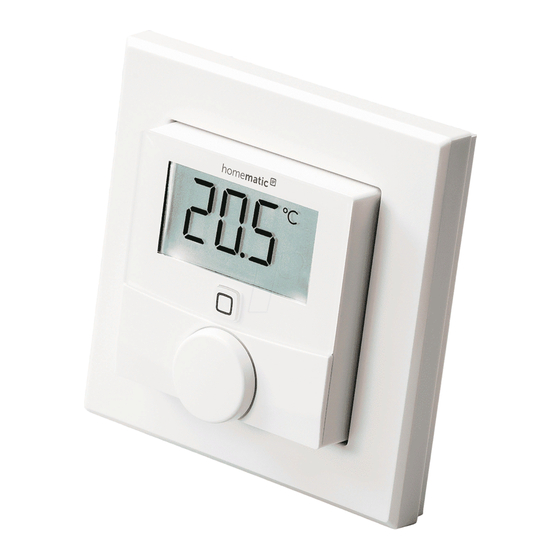
Wall thermostat with humidity sensor
Hide thumbs
Also See for HmIP-WTH-2:
- Mounting instruction and operating manual (90 pages) ,
- Mounting instruction and operating manual (90 pages)

Related Manuals for HomeMatic HmIP-WTH-2


Summary of Contents for HomeMatic HmIP-WTH-2
- Page 1 Wandthermostat mit Luftfeuchtigkeitssensor Wall Thermostat with Humidity Sensor HmIP-WTH-2 Installations- und Bedienungsanleitung Installation and operating manual...
-
Page 2: Table Of Contents
Funktion und Geräteübersicht ..............5 Allgemeine Systeminformationen .............6 Inbetriebnahme .....................6 Anlernen ....................... 6 6.1.1 Anlernen an den Homematic IP Fußbodenheizungsaktor ....6 6.1.2 Anlernen am Homematic IP Access Point ........7 Montage ........................ 8 6.2.1 Klebestreifenmontage ................8 6.2.2 Schraubmontage ...................9 6.2.3 Montage auf einer Unterputzdose ...........10 6.2.4 Montage in Mehrfachkombinationen .......... - Page 3 Bedienung ....................18 Batterien wechseln ..................18 10 Fehlerbehebung ..................19 10.1 Schwache Batterien ..................19 10.2 Befehl nicht bestätigt ..................19 10.3 Duty Cycle ......................20 10.4 Fehlercodes und Blinkfolgen ................21 11 Wiederherstellung der Werkseinstellungen 12 Wartung und Reinigung ................22 13 Allgemeine Hinweise zum Funkbetrieb ..........23 14 Entsorgung ....................23 15 Technische Daten ..................
-
Page 4: Lieferumfang
(CE) ist das eigenmächti- ge Umbauen und/oder Verändern Lesen Sie diese Anleitung sorgfältig, des Gerätes nicht gestattet. bevor Sie Ihre Homematic IP Geräte in Betrieb nehmen. Bewahren Sie die Betreiben Sie das Gerät nur in Anleitung zum späteren Nachschlagen trockener sowie staubfreier Um- auf! Wenn Sie das Gerät anderen Per-... -
Page 5: Funktion Und Geräteübersicht
Sie können den Wandthermostaten direkt an einen Homematic IP Fußbodenheizungsak- tor oder alternativ - für eine bequeme Steuerung per Homematic IP App - an den Homematic IP Access Point anler- nen. Dank des Batteriebetriebs bietet der Wandthermostat eine hohe Flexi- bilität bei der Wahl des Montageortes. -
Page 6: Allgemeine Systeminformationen
Damit der Wandthermostat in Ihr Sys- dienungsanleitung des Fußboden- tem integriert werden und mit anderen heizungsaktors. Geräten kommunizieren kann, muss er zunächst angelernt werden. Sie können den Wandthermostaten zur Steuerung Ihrer Fußbodenheizung entweder direkt an den Homematic IP Fußbodenheizungsaktor oder an den... -
Page 7: Anlernen Am Homematic Ip Access Point
Access Points. Zum Anlernen des Wandthermostats an den Access Point gehen Sie wie folgt vor: • Öffnen Sie die Homematic IP App • Drehen Sie die Elektronikeinheit (B) auf Ihrem Smartphone. auf die Rückseite. • Wählen Sie den Menüpunkt „Gerät •... -
Page 8: Montage
Namen für das Gerät. • Befestigen Sie die Klebestreifen (G) • Die Konfiguration erfolgt anschlie- auf der Rückseite der Montageplat- ßend in der Homematic IP App. te (F) in den dafür vorgesehenen Markierungen. Achten Sie darauf, dass die Schrift auf der Rückseite... -
Page 9: Schraubmontage
Inbetriebnahme für Sie lesbar ist (H) und die Klam- • Zeichnen Sie zwei der Bohrlö- mern der Montageplatte in die cher (J) anhand der Montageplatte Öffnungen des Wandthermostats (diagonal gegenüberliegend) mit rasten. einem Stift an der Wand an. • Entfernen Sie die Folie von den •... -
Page 10: Montage Auf Einer Unterputzdose
Inbetriebnahme • Setzen Sie die Elektronikeinheit Hinweis! Installation nur durch (B) ein. Achten Sie darauf, dass der Personen mit einschlägigen elekt- Schriftzug „TOP“ und die Pfeile auf rotechnischen Kenntnissen und der Rückseite nach oben zeigen Erfahrungen!* und die Klammern der Montage- Durch eine unsachgemäße Installation platte in die Öffnungen der Elekt- gefährden Sie... -
Page 11: Montage In Mehrfachkombinationen
Betriebsmodi und Konfiguration Betriebsmodi und • Art des Versorgungsnetzes (TN- System, IT-System, TT-System) und Konfiguration die daraus folgenden Anschluss- Nach dem Anlernen an einen Fußbo- bedingungen (klassische Nullung, denheizungsaktor und der Montage Schutzerdung, erforderliche Zu- können Sie über das Konfigurations- satzmaßnahmen etc.). -
Page 12: Automatikbetrieb
Betriebsmodi und Konfiguration Manueller Betrieb Automatik Betrieb Manueller Betrieb Im manuellen Betrieb erfolgt die Tem- Urlaubsmodus peraturregelung gemäß der am Stell- rad (E) eingestellten Temperatur. Die 6.4 Bediensperre Temperatur bleibt bis zur nächsten Programmierung der Heizprofile manuellen Änderung erhalten. Um den Datum und Uhrzeit manuellen Betrieb zu aktivieren, gehen Offset Temperatur... -
Page 13: Bediensperre
Betriebsmodi und Konfiguration • Stellen Sie durch Drehen des Stell- • Wählen Sie durch Drehen des Stell- rads Start-Uhrzeit und -Datum ein rads das Symbol „ “ aus und bestä- und bestätigen Sie die Auswahl tigen Sie die Auswahl durch kurzes durch kurzes Drücken des Stell- Drücken des Stellrads. -
Page 14: Heizen Oder Kühlen
Betriebsmodi und Konfiguration Profil 1 - „Pr.Ad“ für das individuelle Ein- stellen des Wochenprofils und Vorkonfiguriert für Heizen per Heizkör- - „OSSF“ zum Aktivieren („On“) perthermostat bzw. Deaktivieren („OFF“) der Montag bis Freitag Temp. Optimum-Start-/Stop-Funktion 00:00 bis 06:00 Uhr 17,0 °C aus. - Page 15 Betriebsmodi und Konfiguration Profil 3 Profil 5 Alternatives Heizprofil Vorkonfiguriert für Kühlen per Fußbo- denheizung Montag bis Sonntag Temp. Montag bis Freitag Temp. 00:00 bis 06:00 Uhr 17,0 °C 00:00 bis 05:00 Uhr 23,0 °C 06:00 bis 22:00 Uhr 21,0 °C 05:00 bis 08:00 Uhr 21,0 °C 22:00 bis 23:59 Uhr...
-
Page 16: Wochenprofil
Betriebsmodi und Konfiguration 7.5.3 Wochenprofil 7.5.4 Optimum-Start-/Stop-Funktion Im Wochenprofil lassen sich für jeden Damit zur festgelegten Zeit die ge- Wochentag des gewählten Heizprofils wünschte Temperatur im Raum bereits separat bis zu 6 Heizphasen (13 Schalt- erreicht wurde, können Sie die Opti- zeitpunkte) individuell einstellen. -
Page 17: Auswahl Der Gewünschten Temperaturanzeige
Sie können die Verbindung zwischen - „ACtH“ für das Anzeigen der Ist- Ihrem Homematic IP Wandthermosta- Temperatur und der aktuellen ten und dem Homematic IP Fußboden- Luftfeuchtigkeit im Wechsel aus heizungsaktor überprüfen. Bei dieser und bestätigen Sie Ihre Auswahl Überprüfung sendet der Wandthermo- durch kurzes Drücken des Stell-... -
Page 18: Bedienung
Wochenpro- fil wieder aktiviert. Im manuellen Betrieb bleibt die Temperatur bis zur nächsten manuellen Änderung erhalten. • Boost-Funktion für Homematic IP Heizkörperthermostate: Drücken Sie das Stellrad (E) des Wand- thermostats kurz, um die Boost- Funktion für schnelles, kurzzeitiges Aufheizen des Heizkörpers durch... -
Page 19: Fehlerbehebung
Fehlerbehebung 10 Fehlerbehebung • Setzen Sie die Elektronikeinheit wieder in den Rahmen. Achten Sie darauf, dass der Schriftzug „TOP“ 10.1 Schwache Batterien und die Pfeile auf der Rückseite der Wenn es der Spannungswert zulässt, ist Elek-tronikeinheit nach oben zei- der Wandthermostat auch bei niedriger gen und die Klammern der Monta- Batteriespannung betriebsbereit. -
Page 20: Duty Cycle
Stunde). Die Geräte dürfen bei Erreichen des 1-%-Limits nicht mehr senden, bis diese zeitliche Begrenzung vorüber ist. Gemäß dieser Richtlinie, werden Homematic IP Geräte zu 100 % normenkonform entwickelt und pro- duziert. Im normalen Betrieb wird der Duty Cycle in der Regel nicht erreicht. Dies kann jedoch in Einzelfällen bei der... -
Page 21: Fehlercodes Und Blinkfolgen
(s. „9 Bat- Batterie-Symbol ( ) Batteriespannung gering terien wechseln“ auf Seite 18). Kommunikationsstörung Prüfen Sie die Verbindung Antennen-Symbol blinkt zum Homematic IP Ac- zum Homematic IP Ac- cess Point/Fußbodenhei- cess Point/Fußbodenhei- zungsaktor zungsaktor. Lüften Sie und stellen Sie Luftfeuchtesysmbol blinkt Feuchtegrenze (60 %) im ggf. -
Page 22: Wiederherstellung Der Werkseinstellungen
Wiederherstellung der Werkseinstellungen Achten Sie auf die Anzeige in Ihrer App oder wenden 6x langes rotes Blinken Gerät defekt Sie sich an Ihren Fach- händler. Nachdem die Testanzeige 1x oranges und 1x grünes Leuchten (nach dem Ein- Testanzeige erloschen ist, legen der Batterien) können Sie fortfahren. -
Page 23: Allgemeine Hinweise Zum Funkbetrieb
Hiermit erklärt die eQ-3 AG, Maiburger Wir machen ausdrücklich darauf auf- Str. 29, 26789 Leer, Deutschland, dass merksam, dass Sie als Endnutzer ei- der Funkanlagentyp Homematic IP genverantwortlich für die Löschung HmIP-WTH-2der Richtlinie 2014/53/EU personenbezogener Daten auf dem zu entspricht. Der vollständige Text der entsorgenden Elektro- und Elektronik- EU-Konformitätserklärung ist unter der... -
Page 24: Technische Daten
Technische Daten 15 Technische Daten Geräte-Kurzbezeichnung: HmIP-WTH-2 Versorgungsspannung: 2x 1,5 V LR03/Micro/AAA Stromaufnahme: 50 mA max. Batterielebensdauer: 2 Jahre (typ.) Schutzart: IP20 Umgebungstemperatur: 0 bis 35 °C Abmessungen (B x H x T): Ohne Rahmen: 55 x 55 x 23,5 mm... - Page 25 Function and device overview ..............28 General system information ..............29 Start-up ......................29 Pairing ......................... 29 6.1.1 Pairing with the Homematic IP Floor Heating Actuator ....29 6.1.2 Pairing the Homematic IP Access Point ..........30 Installation ......................31 6.2.1 Adhesive strip mounting ..............31 6.2.2 Screw mounting ...................
- Page 26 Operation ....................39 Changing the batteries ................40 10 Troubleshooting ..................41 10.1 Low battery ......................41 10.2 Command not confirmed ................41 10.3 Duty Cycle ......................41 10.4 Error codes and flashing sequences .............42 11 Restoring factory settings ................ 43 12 Maintenance and cleaning ...............
-
Page 27: Package Contents
Please read this manual carefully befo- The device may only be operated re operating your Homematic IP com- in dry and dust-free environment ponents. Keep the manual so you can and must be protected from the refer to it at a later date if you need to. -
Page 28: Function And Device Overview
The Homematic IP Wall Thermostat Humidity offers time-controlled regulation of Warning about condensation floor heating systems in connection Open window symbol with Homematic IP Floor Heating Ac- tuators or conventional radiators using Battery symbol Homematic IP Radiator Thermostats Radio transmission according to individually tailored hea- Boost function ting phases. -
Page 29: General System Information
Homematic IP system in combination ting up red. with other components are described If no pairing operations are carried in the Homematic IP User Guide. All out, pairing mode is exited auto- current technical documents and up- matically after 30 seconds. dates are provided at www.homematic-ip.com. -
Page 30: Pairing The Homematic Ip Access Point
To add your wall thermostat to the ac- cess point, please proceed as follows: • To confirm, enter the last four di- • Open the Homematic IP app on gits of the device number (SGTIN) your smartphone. in your app, or scan the QR code. -
Page 31: Installation
Start-up Installation Please read this entire section before starting the installation. You can use the supplied clip-on frame (A) to mount the wall thermostat or ea- sily integrate it into an existing switch (see „6.2.4 Installation in multiple combi- nations“ on page 33). -
Page 32: Mounting On Flush-Mounted Boxes
Start-up • Use a pen to mark the positions of clips on the mounting plate latch bore holes (J) (diagonally opposite) into the openings on the electronic in the mounting plate on the wall. unit. • Now drill the bore holes. 6.2.3 Mounting on flush-mounted boxes If you are working with a stone... -
Page 33: Installation In Multiple Combinations
Start-up Incorrect installation also means that 6.2.4 Installation in multiple combinations you are running the risk of serious damage to property, e.g. from fire. You You can mount the wall thermostat risk personal liability for personal injury with the attachment frame (A) provided and property damage. -
Page 34: Operating Modes And Configuration
Operating modes and configuration Operating modes and Automatic mode In automatic mode, the temperature is configuration controlled in accordance with the set After pairing and mounting the device, week profile (see „6.5.3 Week profile“ you can individually adjust the settings on page 74). -
Page 35: Holiday Mode
Operating modes and configuration Holiday mode • Press and hold down the control wheel (E) to open the configuration The holiday mode can be used if you menu. want to maintain a fixed temperature • Select the symbol by turning the for a certain period (e.g. -
Page 36: Heating Or Cooling
Operating modes and configuration 7.5.1 Heating or cooling Profile 1 You can use your floor heating system Pre-configured heating via radiator to heat rooms during winter or to cool thermostat rooms during summer. Monday to Friday Temp. • Select “HEAT” for heating and 00:00 - 06:00 17,0 °C “COOL”... -
Page 37: Week Profile
Operating modes and configuration Profile 3 Saturday to Sunday Temp. Alternative profile 00:00 - 06:00 23,0 °C Monday to Sunday Temp. 06:00 - 23:00 21,0 °C 00:00 - 06:00 17,0 °C 23:00 - 23:59 23,0 °C 06:00 - 22:00 21,0 °C 22:00 - 23:59 17,0 °C Profil 6... -
Page 38: Optimum Start/Stop Function
Operating modes and configuration • The next time is shown in the dis- rature of e.g. 20 °C is set but the room play. You can change this time presents with only 18 °C, an offset of using the control wheel. -2.0 °C needs to be set. An offset tem- perature of 0.0 °C is set in the factory •... -
Page 39: Configuring The Floor Heating Actuator
(E) to open the configuration menu. You can use this menu item for confi- guring your Homematic IP Floor Hea- • Select the symbol by turning the ting Actuator. control wheel and confirm by pres- • Press and hold down the control sing the control wheel briefly. -
Page 40: Changing The Batteries
Changing the batteries 9 Changing the batteries • Please pay attention to the flashing signals of the device LED while in- If the symbol for empty batteries ( ) serting the batteries (see „10.4 Error appears in the display or in the app, codes and flashing sequences“... -
Page 41: Troubleshooting
If the voltage drops too far during limit until this time restriction comes to transmission, the empty battery symbol an end. Homematic IP devices are de- ( ) and the corresponding error code signed and produced with 100% con- will be displayed on the device (see formity to this regulation. -
Page 42: Error Codes And Flashing Sequences
Battery voltage too low ging the batteries“ on page 40). Communication error Please check the connec- Antenna symbol flashing with Homematic IP access tion to the Homematic IP point/floor heating actu- access point/floor heating ator actuator. Ventilate the room and Flashing humidity symbol... -
Page 43: Restoring Factory Settings
Restoring factory settings Please see your app for 6x long red flashes Device defective error message or contact your retailer. After the test display 1x orange and 1x green light (after inserting batte- Test display has stopped, ries) you can continue. 11 Restoring factory settings 12 Maintenance and cleaning The factory settings of the device... -
Page 44: General Information About Radio Operation
Leer, Germany hereby declares that the of it. radio equipment type Homematic IP HmIP-WTH-2 is compliant with Direc- tive 2014/53/EU. The full text of the EU Information about conformity declaration of conformity is available at The CE mark is a free trademark that is... -
Page 45: Technical Specifications
Technical specifications 15 Technical specifications Device short description: HmIP-WTH-2 Supply voltage: 2x 1.5 V LR03/micro/AAA Current consumption: 50 mA max. Battery life: 2 years (typ.) Degree of protection: IP20 Ambient temperature: 0 to 35 °C Dimensions (W x H x D): Without frame: 55 x 55 x 23.5 mm... - Page 46 Kostenloser Download der Homematic IP App! Free download of the Homematic IP app! Bevollmächtigter des Herstellers: Manufacturer’s authorised representative: eQ-3 AG Maiburger Straße 29 26789 Leer / GERMANY www.eQ-3.de...
Need help?
Do you have a question about the HmIP-WTH-2 and is the answer not in the manual?
Questions and answers