Table of Contents
Advertisement
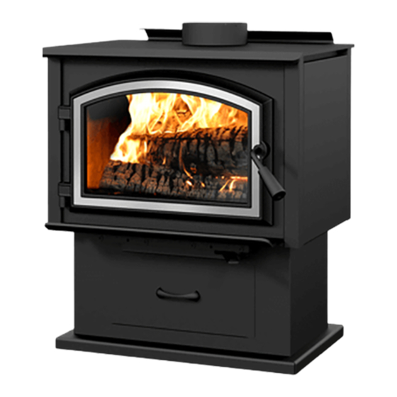
Installation and Operation Manual
OSBURN 1700
(OB01700 model)
US Environmental Protection Agency
phase II certified wood stove compliant
with 2020 cord wood standard
Safety tested according to ULC S627,
UL 1482 and UL 737 standards by an
accredited laboratory.
MOBILE
HOME
CONTACT LOCAL BUILDING OR FIRE OFFICIALS ABOUT RESTRICTIONS AND INSTALLATION INSPECTION REQUIREMENTS IN
LOCAL AREA.
READ THIS ENTIRE MANUAL BEFORE INSTALLATION AND USE OF THIS WOOD STOVE. FAILURE TO FOLLOW THESE
INSTRUCTIONS COULD RESULT IN PROPERTY DAMAGE, BODILY INJURY OR EVEN DEATH.
READ AND KEEP THIS MANUAL FOR REFERENCE
Printed in Canada
45982A
Advertisement
Table of Contents

Related Manuals for Osburn Beyond Fire 1700


Summary of Contents for Osburn Beyond Fire 1700
- Page 1 Installation and Operation Manual OSBURN 1700 (OB01700 model) US Environmental Protection Agency phase II certified wood stove compliant with 2020 cord wood standard Safety tested according to ULC S627, UL 1482 and UL 737 standards by an accredited laboratory. MOBILE...
- Page 3 It is also highly recommended to register the warranty online at https://www.osburn-mfg.com/en/warranty/warranty-registration/ Registering the warranty will help to quickly find the information needed on the unit.
-
Page 4: Table Of Contents
TABLE OF CONTENTS PART A - OPERATION AND MAINTENANCE ................7 1. Safety Information ........................7 2. General Information ........................ 8 2.1 Performances ........................8 2.2 Specifications ........................9 2.3 Dimensions ........................10 2.4 Materials ...........................14 2.5 Zone Heating ........................14 2.6 Emissions and Efficiency ....................15 3. - Page 5 Appendix 7: Optional Blower and Thermodisc Installation ............. 55 Appendix 8: Air Tubes and Baffle Installation ................56 Appendix 9: Mobile Home Installation ..................58 Appendix 10: Exploded Diagram and Parts List ..............59 Osburn Limited Lifetime Warranty ..................... 62 Dealer: Installer: Phone Number:...
- Page 6 Certification Plate Page 6 Installation and Operation Manual - 1700...
-
Page 7: Part A - Operation And Maintenance
PART A - OPERATION AND MAINTENANCE 1. Safety Information • This stove has been tested for use with an open door in conjunction with a fire screen, sold separately. The door may be opened, or fire screen removed only during lighting procedures or reloading. -
Page 8: General Information
Performances Values are as measured per test method, except for the recommended heating area, firebox volume, maximum burn time and maximum heat output. Model OSBURN 1700 (OB01700) Fuel Type Dry Cordwood Recommended heating area (sq. ft. 500 to 1,800 ft... -
Page 9: Specifications
Specifications Maximum log length 17 in (432 mm) east-west Flue outlet diameter 6 in (150 mm) Recommended connector pipe diameter 6 in (150 mm) Type of chimney ULC S629, UL 103 HT (2100 °F) Baffle material C-Cast Approved for alcove installation Approved for mobile home installation Type of door Simple, glass with cast iron frame... -
Page 10: Dimensions
Dimensions 2.3.1 Stove Dimensions with Legs 24 7/8" 632mm 12 1/2" 316mm 6 5/8" 167mm 6" Ø 150 m Figure 1: Top View 23 1/4" 590mm 22 3/4" 578mm 19 1/4" 490mm 17 1/2" 444mm 10 7/8" 276mm 9 3/8" 239mm 15 3/4"... - Page 11 2.3.2 Stove Dimensions with Structural Legs 24 7/8" 632mm 12 1/2" 316mm 6 5/8" 167mm 6" Ø 150 mm Figure 4: Top View 23 1/4" 590mm 22 3/4" 578mm 19 1/4" 490mm 17 1/2" 444mm 10 7/8" 276mm 9 3/8" 239mm 15 3/4"...
- Page 12 2.3.3 Dimensions with pedestal 24 7/8" 632mm 12 1/2" 316mm 6 5/8" 167mm 6" Ø 150 m Figure 7: Top View 23 1/4" 590mm 22 3/4" 578mm 19 1/4" 490mm 17 1/2" 444mm 10 7/8" 276mm 9 3/8" 240mm 15 3/4" 399mm 22 1/2"...
- Page 13 2.3.4 Combustion Chamber Dimensions 8 3/4" 221mm 17 1/4" 438mm Figure 10: Door Opening 3/16" 5/16" 19 5/8" 11 7/8" 498mm 301mm 13 1/2" 343mm Figure 11: Front View - Combustion Chamber Figure 12: Side View - Combustion Chamber Installation and Operation Manual - 1700 Page 13...
-
Page 14: Materials
Materials The body of this stove, which is most of its weight, is carbon steel. Should it ever become necessary many years in the future, almost the entire stove can be recycled into new products, thus eliminating the need to mine new materials. The paint coating on the stove is very thin. -
Page 15: Emissions And Efficiency
The success of zone heating will depend on several factors, including the correct sizing and location of the stove, the size, layout and age of your home and your climate zone. Three-season vacation homes can usually be heated with smaller stoves than houses that are heated all winter. Emissions and Efficiency The low smoke emissions produced by the special features inside this stove firebox mean that the household will release up to 90% less smoke into the outside environment than if an older... -
Page 16: Log Length
Softer woods make good fuel for mild weather in spring and fall because they light quickly and produce less heat. Softwoods are not as dense as hardwoods so a given volume of wood contains less energy. Using softwoods avoids overheating the house, which can be a common problem with wood heating in moderate weather. - Page 17 Firewood with a moisture content between 15% and 20% will allow the stove to produce its highest possible efficiency. Here are some facts to consider in estimating drying time: − Firewood bought from a dealer is rarely dry enough to burn, so it is advisable to buy the wood in spring and dry it yourself;...
-
Page 18: The Use Of A Fire Screen
4. Operating the Stove This wood heater has a manufacturer-set minimum low burn rate that must not be altered. It is against federal regulations to alter this setting or otherwise operate this wood heater in a manner inconsistent with operating instructions in this manual. Before using the stove, the following steps should be completed : •... -
Page 19: Burning Wood Efficiently
4.2 Blower Operation Ensure the blower cord is not in contact with any surface of the stove to prevent electrical shock or fire damage. Do not run cord beneath the stove. It is possible to install a blower on this stove. The blower is optional and is sold separately. -
Page 20: Lighting Fires
Lighting Fires Each person heating with wood develops its own favorite way to light fires. Regardless of the method chosen, the goal should be to have a hot fire burning, quickly. A fire that ignites fast produces less smoke and deposits less creosote in the chimney. Never use gasoline, gasoline-type lantern fuel (naphtha), fuel oil, motor oil, kerosene, charcoal lighter fluid, or similar liquids or aerosols to start or ‘freshen up’... -
Page 21: Combustion Cycles
5.2.4 Using Fire Starters Commercial fire starters can be used instead of a newspaper. Some of these starters are made of sawdust and wax and others are made of specialized flammable solid chemicals. Always follow the package directions when using. Gel starters can also be used, but only to light a fire, in a cold combustion chamber without hot embers inside. -
Page 22: Removing Ashes
Raking the coals is useful for two reasons. First, it brings them near where most of the combustion air enters the firebox. This will ignite the new load quickly. Secondly, the charcoal will not be smothered by the new load of wood. When the embers are simply spread inside the combustion chamber, the new load smoulder for a long time before igniting. -
Page 23: Fire Types
On the other hand, too much air can make the fire uncontrollable, creating very high temperatures in the unit as well as in the chimney and seriously damaging them. A reddish glow on the unit and on the chimney components indicates overheating. Excessive temperatures can cause a chimney fire. Fire Types Using the air intake control is not the only way to match the appliance heat output to the desired temperature in the house. -
Page 24: Maintenance
The table below gives an approximate maximum burn cycle time, based on firebox volume. Table 1 : Approximate Maximum Burn Cycle Time FIREBOX VOLUME MAXIMUM BURN CYCLE TIME <1.5 cubic feet 3 to 5 hours 1.5 c.f. to 2.0 c.f 5 to 6 hours 2.0 c.f. -
Page 25: Heater
Heater 6.1.1 Cleaning and Painting Painted and plated surfaces can be wiped down with a soft, damp cloth. If the paint is scratched or damaged, it is possible to repaint the heater with a heat-resistant paint. Do not clean or paint the appliance when it is hot. -
Page 26: Door
To remove or replace the glass (D): Remove the door (E) from its hinges and lay it on a soft, flat surface. Remove the eight screws (A), the eight glass retainers (B), and the metal frames (C). Remove the glass (D). If it is damaged install a new one in place. -
Page 27: Exhaust System
6.3.1 Adjustment In order for the stove to burn at its best efficiency, the door must provide a perfect seal with the firebox. Therefore, the gasket should be inspected periodically to check for a good seal. The gasket seal may be improved with a simple latch mechanism adjustment: Remove the split pin by pulling and turning it using pliers. -
Page 28: Frequency
«Creosote - Formation and Need to Removal When wood is burned slowly, it produces tar and other organic vapors, which combine with expelled moisture to form creosote. The creosote vapors condense in the relatively cooler chimney flue of a slow-burning fire. As a result, creosote residue accumulates on the flue lining. -
Page 29: Part B - Installation
PART B - INSTALLATION 7. Safety Information and Standards • The information given on the certification label affixed to the appliance always overrides the information published, in any other media (owner’s manual, catalogues, flyers, magazines and web sites). • Mixing of appliance components from different sources or modifying components may result in hazardous conditions. -
Page 30: Location Of The Certification Label
Location of the Certification Label Since the information given on the certification label affixed to the appliance always overrides the information published, in any other media (owner’s manual, catalogues, flyers, magazines and web sites) it is important to refer to it in order to have a safe and compliant installation. In addition, important information about the stove can be found (model, serial number, etc.). - Page 31 48" 36" 122 cm 92 cm Figure 19: Clearances - Top Figure 20: Clearances - Corner 84" (L) 213 cm Figure 21: Clearances - Side Installation and Operation Manual - 1700 Page 31...
-
Page 32: Clearances
Clearances APPLIANCE CLEARANCES WITH SINGLE APPLIANCE CLEARANCES WITH DOUBLE WALL PIPE CONNECTOR WALL PIPE CONNECTOR Canada Canada 14 ½" (368 mm) 13" (330 mm) 6" (152 mm) 6" (152 mm) 10" (254 mm) 10" (254 mm) 10" (254 mm) 10" (254 mm) 12"... - Page 33 8.1.2 With Lowered Ceiling APPLIANCE CLEARANCES WITH SINGLE APPLIANCE CLEARANCES WITH DOUBLE WALL PIPE CONNECTOR WALL PIPE CONNECTOR Canada Canada 14 ½" (368 mm) 14 ½" (368 mm) 9 ½" (241 mm) 9 ½" (241 mm) 12" (305 mm) 12" (305 mm) 12"...
- Page 34 8.1.4 Inside an Alcove APPLIANCE CLEARANCES WITH DOUBLE DISTANCES FROM PIPE CONNECTOR WALL PIPE CONNECTOR WITH DOUBLE WALL PIPE CONNECTOR Canada Canada 16" (406 mm) 16" (406 mm) 12 ½" (318 mm) 12 ½" (318 mm) 16" (406 mm) 16" (406 mm) 25"...
-
Page 35: Floor Protection
Floor Protection This stove is designed to prevent the floor from overheating. However, it must be placed on a non-flammable surface to protect the floor from hot embers that may fall during loading. The floor protection must be a continuous, non combustible material, such as steel with a minimum thickness of 0.015"... - Page 36 8.3.1 Shield Construction Rules − Adhesives used in shield construction must not ignite or lose adhesive qualities at temperatures likely to be encountered. − Mounting hardware which extends from the shield surface into combustibles may be used only at the edges of the shield. −...
- Page 37 Figure 24: Heat shield clearances Figure 25: Heat shield clearances Figure 26: Heat shield clearances Installation and Operation Manual - 1700 Page 37...
- Page 38 CLEARANCES MAY BE REDUCED BY THESE PERCENTAGES TYPE OF SHIELD SIDES AND REAR TOP (CEILING) CAN / CAN / USA (%) MIN. USA (%) MIN. Sheet metal, a minimum of 24 gauge (0.61 mm) in thickness , spaced out at least 1" (25 mm)* by non-combustible spacers 12"...
-
Page 39: The Venting System
9. The Venting System General The venting system, made of the chimney and the connecting pipe between the stove and the chimney, acts as the engine that drives the wood heating system. Even the best stove will not function safely and efficiently if it is not connected to a suitable chimney. The heat in the flue gases that pass from the stove and chimney connector into the chimney is not waste heat. - Page 40 9.2.2 Factory-Built Metal Chimneys in Mobile Homes For use in a mobile home, this stove is to be connected to a 6" double wall factory built chimney pipe conforming to ULC-S629 or UL 103HT standards for 650°C Factory-built chimney. The total length of the flue system should be at least 12 feet including elbows, from the top of the stove.
-
Page 41: Minimum Chimney Height
Minimum Chimney Height The top of the chimney should be tall enough to be above the air turbulence caused when wind blows against the house and its roof. The chimney must extend at least 3 ft. (1 m) above the highest point of contact with the roof, and at least 2 ft. -
Page 42: Supply Of Combustion Air
When it is cold outside, the warm air in the house is buoyant so it tends to rise. This creates a slight pressure difference in the house. Called ‘stack effect’, it produces a slightly negative pressure in the lower part of the house (compared to the outside) and a slightly positive pressure zone in the high part of the house. -
Page 43: Installing The Chimney Connector
9.5.2 Conventional House The safest and most reliable supply of combustion air for a wood stove is from the room in which it is installed. Room air is already preheated so it will not chill the fire, and its availability is not affected by wind pressures on the house. - Page 44 Double wall chimney connectors are tested and certified. The rules for double wall pipe are found in the manufacturer’s installation instructions. These rules will be very different than those for single wall. 9.6.1 Installation of Single Wall Chimney Connector The chimney connector assembly has been called ‘the weak link’ in the safety of wood heating systems because failure to install the connector properly (which has been common in the past) can result in house fires.
- Page 45 • Galvanized flue pipes must not be used because the coatings vaporize at high temperatures and release dangerous gases. Use black painted flue pipes. • Flue pipes must be at least 24 gauge in thickness. • Flue pipe joints should overlap 1 ¼" (30 mm). •...
-
Page 46: Appendix 1: Legs Installation
APPENDIx 1: LEGS INSTALLATION Remove the door, the firebricks, and the ash plug from the stove, if desired. Put the stove on its back. Remove and dispose of the two freight supports (D). Keep the nuts (C) and washers (B) for step 4. Page 46 Installation and Operation Manual - 1700... - Page 47 Install the legs (E) on the legs supports (F). Secure with the washers (G) and nuts (H) supplied with the leg assembly. With the nuts (C) and washers (B) removed in step 2, secure both leg assemblies to the stove. Installation and Operation Manual - 1700 Page 47...
- Page 48 Install the air control cover (J) with screws (K) and nuts (L). Put the stove on its legs, install the ash drawer included with the kit. Put back the firebricks, the ash plug and the door on the stove. See step 1. The baffle and the bricks must be put back in the right place after the final positioning of the stove.
-
Page 49: Appendix 2: Pedestal Installation
APPENDIx 2: PEDESTAL INSTALLATION Remove the door, the firebricks and the ash plug from the stove, if desired. Put the stove on its back. Remove and dispose of the two freight supports (D). Keep the nuts (C) and washers (B) for step 3. Installation and Operation Manual - 1700 Page 49... - Page 50 Install the pedestal (E) on the stove and screw it in place using washers (B) and nuts (C). Put the stove on its pedestal and install the fresh air panel (F) with the screws (G), the air control cover (H) with the screws (J) and install the ash drawer (K). Put back the bricks, the spacers, the ash plug and the door on the stove.
-
Page 51: Appendix 3: Door Overlay Installation
APPENDIx 3: DOOR OVERLAY INSTALLATION Position the overlay (A) on the door frame and secure it in place from behind using the nuts (B). To ease the installation, do not tighten the nuts until they are all installed. Note: It is not necessary to remove the glass to install the overlay. Installation and Operation Manual - 1700 Page 51... -
Page 52: Appendix 4: Decorative Panels
APPENDIx 4: DECORATIVE PANELS To remove the decorative panel (C), remove the screws (B) and push forward on the panel to unhook it from the bracket (E). Page 52 Installation and Operation Manual - 1700... -
Page 53: Appendix 5: Optional Fresh Air Intake Kit Installation
APPENDIx 5: OPTIONAL FRESH AIR INTAKE KIT INSTALLATION This mobile home approved stove requires the installation of a fresh air intake kit (A) and an insulated fresh air intake pipe (HVAC type, must meet ULC S110 or UL 181 class 0 or class 1) (B), sold separately. -
Page 54: Appendix 6: Optional Fire Screen Installation
APPENDIx 6: OPTIONAL FIRE SCREEN INSTALLATION Open the door. Hold the fire screen by the two handles and bring it close to the door opening. Lean the upper part of the fire screen against the top door opening making sure to stove the top fire screen brackets behind the primary air deflector. -
Page 55: Appendix 7: Optional Blower And Thermodisc Installation
APPENDIx 7: OPTIONAL BLOWER AND THERMODISC INSTALLATION A blower and a thermodisc, sold separately, can be installed on the stove. The installation of the blower is identical for a stove on legs or pedestal. Thermodisc allows the blower to operate only when the stove is hot enough. -
Page 56: Appendix 8: Air Tubes And Baffle Installation
APPENDIx 8: AIR TUBES AND BAFFLE INSTALLATION Starting with the rear tube, lean and insert the right end of the secondary air tube into the rear right channel hole. Then lift and insert the left end of the tube into the rear left channel. Align the notch in the left end of the tube with the key of the left air channel hole. - Page 57 Note that secondary air tubes (B) can be replaced without removing the baffle board (A) and that all tubes are identical. Installation and Operation Manual - 1700 Page 57...
-
Page 58: Appendix 9: Mobile Home Installation
APPENDIx 9: MOBILE HOME INSTALLATION For a stove on legs, install a plate (L) on each leg and screw it in place with the proper hardware (M). For a stove on a pedestal, remove the plugs (N) and screw the base on the floor with the proper hardware (O). -
Page 59: Appendix 10: Exploded Diagram And Parts List
APPENDIx 10: ExPLODED DIAGRAM AND PARTS LIST DETAIL A Installation and Operation Manual - 1700 Page 59... - Page 60 GLASS RETAINER KIT WITH SCREWS (12 PER KIT) SE65011 ASH LIP ASSEMBLY 30507 BLACK TORX SCREW WITH FLAT HEAD TYPE F 1/4-20 X 3/4" OA10132 GLASS ASH LIP SE45982 OSBURN 1700 INSTRUCTIONS MANUAL KIT PL70594 DECORATIVE PANEL 24096 ROUND CAST IRON ASH PLUG PL70686 AIR DEFLECTOR 30154 BLACK SCREW #10 X 5/8"...
- Page 61 Item Description 44085 RHEOSTAT KNOB 44087 RHEOSTAT NUT 44080 RHEOSTAT WITHOUT NUT (MODEL KBMS-13BV) SE70532 AIR CONTROL DAMPER ASSEMBLY 30206 ZINC WASHER 5/16"ID X 3/4"OD 30506 SCREW PAN TORX TYPE F 1/4-20 X 1" BLACK AC05959 METALLIC BLACK STOVE PAINT - 342 g (12oz) AEROSOL OA10244 PEDESTAL WITH ASH PAN 17/64"...
-
Page 62: Osburn Limited Lifetime Warranty
Shall your unit or a component be defective, contact immediately your OSBURN dealer. To accelerate processing of your warranty claim, make sure to have on hand the following information when calling: •... - Page 64 Resale is strictly prohibited. The manufacturer may update St-Augustin-de-Desmaures (Québec) Canada this document from time to time and cannot be responsible G3A 2H3 for problems, injuries, or damages arising out of the use 418-908-8002 of information contained in any document obtained from www.osburn-mfg.com/en unauthorized sources. tech@sbi-international.com...
Need help?
Do you have a question about the Beyond Fire 1700 and is the answer not in the manual?
Questions and answers