Table of Contents
Advertisement
Quick Links
Installation and Operation Manual
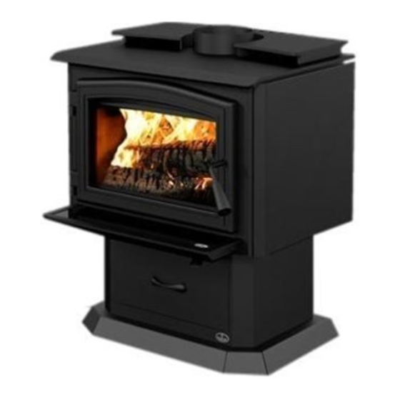
OSBURN 1700
(OB01700 model)
US Environmental Protection Agency
phase II certified wood stove compliant
with 2020 cord wood standard
Safety tested according to ULC S627,
UL 1482 and UL 737 standards by an
accredited laboratory.
MOBILE
HOME
CONTACT LOCAL BUILDING OR FIRE OFFICIALS ABOUT RESTRICTIONS AND INSTALLATION INSPECTION REQUIREMENTS IN
LOCAL AREA.
READ THIS ENTIRE MANUAL BEFORE INSTALLATION AND USE OF THIS WOOD STOVE. FAILURE TO FOLLOW THESE
INSTRUCTIONS COULD RESULT IN PROPERTY DAMAGE, BODILY INJURY OR EVEN DEATH.
READ AND KEEP THIS MANUAL FOR REFERENCE
Printed in Canada
45982A
2021-05-06
Advertisement
Table of Contents

Related Manuals for Osburn 1700


Summary of Contents for Osburn 1700
- Page 1 Installation and Operation Manual OSBURN 1700 (OB01700 model) US Environmental Protection Agency phase II certified wood stove compliant with 2020 cord wood standard Safety tested according to ULC S627, UL 1482 and UL 737 standards by an accredited laboratory. MOBILE...
- Page 3 It is also highly recommended to register the warranty online at https://www.osburn-mfg.com/en/warranty/warranty-registration/ Registering the warranty will help to quickly find the information needed on the unit. Installation and Operation Manual - 1700 Page 3...
-
Page 4: Table Of Contents
7. Safety Information and Standards ..................29 7.1 Mobile Home ........................29 7.2 Regulations Covering Stove Installation ................29 7.3 Location of the Certification Label ..................30 8. Clearances to Combustible Material ..................30 8.1 Clearances ........................32 Page 4 Installation and Operation Manual - 1700... - Page 5 Appendix 8: Air Tubes and Baffle Installation ................56 Appendix 9: Mobile Home Installation ..................58 Appendix 10: Exploded Diagram and Parts List ..............59 Osburn Limited Lifetime Warranty ..................... 62 Dealer: Installer: Phone Number: Serial Number: Installation and Operation Manual - 1700 Page 5...
- Page 6 Certification Plate Page 6 Installation and Operation Manual - 1700...
-
Page 7: Part A - Operation And Maintenance
This product can expose you to chemicals including carbon monoxide, which is known to the State of California to cause cancer, birth defects or other reproductive harm. For more information go to www.P65warnings.ca.gov/ Installation and Operation Manual - 1700 Page 7... -
Page 8: General Information
This appliance is officially tested and certified by an independent agency. Tested and certified in compliance with CFR 40 part 60, subpart AAA, section 60.534(a)(1(ii) and draft ASTM WK47329-14 based on the ATM send by EPA on October 12th, 2017. Carbon monoxide. Page 8 Installation and Operation Manual - 1700... -
Page 9: Specifications
Z240 MH standard. Tested and certified in compliance with CFR 40 part 60, subpart AAA, section 60.534(a)(1(ii) and draft ASTM WK47329-14 based on the ATM send by EPA on October 12th, 2017. Installation and Operation Manual - 1700 Page 9... -
Page 10: Dimensions
19 1/4" 490mm 17 1/2" 444mm 10 7/8" 276mm 9 3/8" 239mm 15 3/4" 399mm 24 1/2" 622mm 25 7/8" 658mm 17 7/8" Figure 2: Front View Figure 3: Side View 454mm Page 10 Installation and Operation Manual - 1700... - Page 11 578mm 19 1/4" 490mm 17 1/2" 444mm 10 7/8" 276mm 9 3/8" 239mm 15 3/4" 399mm 24 1/2" 622mm 25" 635mm 17 5/8" Figure 5: Front View Figure 6: Side View 449mm Installation and Operation Manual - 1700 Page 11...
- Page 12 19 1/4" 490mm 17 1/2" 444mm 10 7/8" 276mm 9 3/8" 240mm 15 3/4" 399mm 22 1/2" 572mm 23 3/8" 595mm 14 7/8" 376mm Figure 8: Front View Figure 9: Side View Page 12 Installation and Operation Manual - 1700...
- Page 13 17 1/4" 438mm Figure 10: Door Opening 3/16" 5/16" 19 5/8" 11 7/8" 498mm 301mm 13 1/2" 343mm Figure 11: Front View - Combustion Chamber Figure 12: Side View - Combustion Chamber Installation and Operation Manual - 1700 Page 13...
-
Page 14: Materials
Although the stove may be able to heat the main living areas of the house to an adequate temperature, it is strongly recommended to also have a conventional oil, gas or electric heating system to provide backup heating. Page 14 Installation and Operation Manual - 1700... -
Page 15: Emissions And Efficiency
Hardwoods are denser than softwoods. Homeowners with access to both hardwood and softwood use both types for different purposes. Installation and Operation Manual - 1700 Page 15... -
Page 16: Log Length
Firewood that is not dry enough to burn is the cause of most complaints about wood burning appliances. Continually burning green or unseasoned wood produces more creosote and involves lack of heat and dirty glass door. Page 16 Installation and Operation Manual - 1700... - Page 17 − Dry wood is much lighter in weight than wet wood, − The face of a fresh cut feels warm and dry; − The moisture content read by a moisture meter is between 15% to 20%. Installation and Operation Manual - 1700 Page 17...
-
Page 18: The Use Of A Fire Screen
OPERATING THE STOVE WITH A FIRE SCREEN INCREASES POSSIBILITIES OF GENERATING CARBON MONOXIDE. CARBON MONOXIDE IS AN ODOURLESS GAS THAT IS HIGHLY TOXIC WHICH CAN CAUSE DEATH AT HIGH CONCENTRATION IN AIR. Page 18 Installation and Operation Manual - 1700... -
Page 19: Burning Wood Efficiently
As hotter and hotter fires are burned, more of the painted surfaces reach the curing temperature of the paint. The smell of curing paint does not disappear until one or two very hot fires have been burned. Installation and Operation Manual - 1700 Page 19... -
Page 20: Lighting Fires
Two spit logs are placed in the firebox with a few sheets of twisted newspapers in between the logs. Fine kindling is added across the two logs and some larger kindling across those, log cabin style. Newspaper is lit. Page 20 Installation and Operation Manual - 1700... -
Page 21: Combustion Cycles
Remove excess ash from the front of the firebox and bring the ashes forward. Place a new load of wood on, and at the back of the embers. Open the air control completely and close the door. Installation and Operation Manual - 1700 Page 21... -
Page 22: Removing Ashes
If the wood is dry and the air control is used properly, the flames should decrease, but remain bright and stable. Page 22 Installation and Operation Manual - 1700... -
Page 23: Fire Types
− the size of the space to be heated, − the amount of wood loaded, − the climate zone where the house is, and − the species of wood, − the time of the year. − the wood moisture content, Installation and Operation Manual - 1700 Page 23... -
Page 24: Maintenance
To avoid premature deterioration, follow the lighting and reloading procedures in section «5. Burning Wood Efficiently» and also avoid letting the heater run with the air intake fully open for entire burn cycles. Page 24 Installation and Operation Manual - 1700... -
Page 25: Heater
The glass used is a ceramic glass, 5/32" (4 mm) thick, 15 ¾" x 9 ⅜" (400 mm x 238 mm), tested to reach temperatures up to 1400º F. If the glass breaks, it must be replaced with one having the same specification. Installation and Operation Manual - 1700 Page 25... -
Page 26: Door
The test must be performed all around the door. If the paper slips out easily anywhere, either adjust the door or replace the gasket. Page 26 Installation and Operation Manual - 1700... -
Page 27: Exhaust System
Smouldering, smoky fires can quickly cause a thick layer of creosote to form. When the stove is operated properly, the exhaust from the chimney is mostly clear and creosote builds up more slowly. Installation and Operation Manual - 1700 Page 27... -
Page 28: Frequency
Do not use the appliance again until the stove and its chimney have been inspected by a qualified chimney sweep or a fire department inspector. Page 28 Installation and Operation Manual - 1700... -
Page 29: Part B - Installation
This stove must be connected to a chimney complying with the requirements for Type HT chimneys in the Standard for Factory-Built Chimneys for Residential Type and Building Heating Appliances, UL 103 and ULC S629 or to a code-approved masonry chimney with a flue liner. Installation and Operation Manual - 1700 Page 29... -
Page 30: Location Of The Certification Label
For a safe way to reduce clearances refer to section «8.3 Reducing Wall and Ceiling Clearances Safely» Page 30 Installation and Operation Manual - 1700... - Page 31 48" 36" 122 cm 92 cm Figure 19: Clearances - Top Figure 20: Clearances - Corner 84" (L) 213 cm Figure 21: Clearances - Side Installation and Operation Manual - 1700 Page 31...
-
Page 32: Clearances
11 ¼" (286 mm) 11 ¼" (286 mm) The pipe distances listed in this table refer to the distances obtained when the stove is installed in accordance with the appliance clearances above mentioned. Page 32 Installation and Operation Manual - 1700... - Page 33 11 ¼" (286 mm) 78" (1981 mm) 78" (1981 mm) The pipe distances listed in this table refer to the distances obtained when the stove is installed in accordance with the appliance clearances above mentioned. Installation and Operation Manual - 1700 Page 33...
- Page 34 11 ¾" (298 mm) 84" (2130 mm) 84" (2130 mm) The pipe distances listed in this table refer to the distances obtained when the stove is installed in accordance with the appliance clearances above mentioned. Page 34 Installation and Operation Manual - 1700...
-
Page 35: Floor Protection
The floor protection at the back of the stove is limited to the stove’s required clearance if such clearance is smaller than 8 inches (203 mm). Only required under the horizontal section (Ho) of the connector. Must exceed each side of the connector by at least 2 inches (51 mm). »Figure 21: Clearances - Side» Installation and Operation Manual - 1700 Page 35... - Page 36 Mounting hardware must not be located closer than 8" (200 mm) from the vertical centre line of the appliance. G) Edge clearance for ceiling shields to side and back walls: 3" (75 mm). Shield extension beyond each side of the appliance: 18" (450 mm). Page 36 Installation and Operation Manual - 1700...
- Page 37 Figure 24: Heat shield clearances Figure 25: Heat shield clearances Figure 26: Heat shield clearances Installation and Operation Manual - 1700 Page 37...
- Page 38 Brick, with a minimum of 24 gauge (0.61 mm) sheet metal backing, spaced out at least 1" (25 mm)* by non-combustible spacers 12" (305 mm) * In Canada this space can be ⅞" (21 mm). Page 38 Installation and Operation Manual - 1700...
-
Page 39: The Venting System
Only components intended for the brand and model of chimney should be used. Never fabricate or substitute parts from other chimney brands. The chimney must be a type suitable for solid fuel. Installation and Operation Manual - 1700 Page 39... - Page 40 Do not downsize the flue to less than 6" unless the venting system is straight and exceeds 25 feet in height. When passing through a combustible wall, the use of an insulated listed thimble is required. Page 40 Installation and Operation Manual - 1700...
-
Page 41: Minimum Chimney Height
Although they are common in North America, chimneys that exit a house wall and run up outside can cause problems. Figure 27: Good System Design Figure 28: Inferior System Design Installation and Operation Manual - 1700 Page 41... -
Page 42: Supply Of Combustion Air
UL 181, Class 0 or Class 1) to the fresh air intake. Where a mobile home has been converted to a standard house by mounting it on a permanent basement foundation, the supply of outdoor air is not required. Page 42 Installation and Operation Manual - 1700... -
Page 43: Installing The Chimney Connector
These components are not usually tested to a particular standard and certified as compliant. Therefore, a list of rules found in solid fuel installation codes apply to the installation of a single wall pipe. Installation and Operation Manual - 1700 Page 43... - Page 44 12 ft. (3.66 m). A chimney which is too short may lack the “tunnel effect” required to obtain a proper draft. • Maximum number of 90-degree elbows: 2. • Maximum unsupported horizontal length: 3 ft. (1 m). Page 44 Installation and Operation Manual - 1700...
- Page 45 • A straight flue pipe assembly offers the least restriction to gas flow and results in a stronger draft. Straight assemblies also need less maintenance because there are no corners to collect creosote. • The chimney connector must be clean and in good condition. Installation and Operation Manual - 1700 Page 45...
-
Page 46: Appendix 1: Legs Installation
Remove the door, the firebricks, and the ash plug from the stove, if desired. Put the stove on its back. Remove and dispose of the two freight supports (D). Keep the nuts (C) and washers (B) for step 4. Page 46 Installation and Operation Manual - 1700... - Page 47 Install the legs (E) on the legs supports (F). Secure with the washers (G) and nuts (H) supplied with the leg assembly. With the nuts (C) and washers (B) removed in step 2, secure both leg assemblies to the stove. Installation and Operation Manual - 1700 Page 47...
- Page 48 Put the stove on its legs, install the ash drawer included with the kit. Put back the firebricks, the ash plug and the door on the stove. See step 1. The baffle and the bricks must be put back in the right place after the final positioning of the stove. Page 48 Installation and Operation Manual - 1700...
-
Page 49: Appendix 2: Pedestal Installation
Remove the door, the firebricks and the ash plug from the stove, if desired. Put the stove on its back. Remove and dispose of the two freight supports (D). Keep the nuts (C) and washers (B) for step 3. Installation and Operation Manual - 1700 Page 49... - Page 50 See step 1. The baffle and the bricks must be put back in the right place after the final positioning of the stove. Page 50 Installation and Operation Manual - 1700...
-
Page 51: Appendix 3: Door Overlay Installation
Position the overlay (A) on the door frame and secure it in place from behind using the nuts (B). To ease the installation, do not tighten the nuts until they are all installed. Note: It is not necessary to remove the glass to install the overlay. Installation and Operation Manual - 1700 Page 51... -
Page 52: Appendix 4: Decorative Panels
APPENDIx 4: DECORATIVE PANELS To remove the decorative panel (C), remove the screws (B) and push forward on the panel to unhook it from the bracket (E). Page 52 Installation and Operation Manual - 1700... -
Page 53: Appendix 5: Optional Fresh Air Intake Kit Installation
(HVAC type, must meet ULC S110 or UL 181 class 0 or class 1) (B), sold separately. Refer to air intake kit installation instructions for more details. Installation with legs Installation with pedestal Installation and Operation Manual - 1700 Page 53... -
Page 54: Appendix 6: Optional Fire Screen Installation
Lift the fire screen upwards and push the bottom part towards the stove then let the fire screen rest on the bottom of the door opening. Warning: Never leave the stove unattended while in use with the fire screen. Page 54 Installation and Operation Manual - 1700... -
Page 55: Appendix 7: Optional Blower And Thermodisc Installation
Ensure that the blower’s power cord is not in contact with any surface of the stove to prevent electrical shock or fire damage. Do not run the power cord beneath the stove. Installation and Operation Manual - 1700 Page 55... -
Page 56: Appendix 8: Air Tubes And Baffle Installation
Put the baffle in place. Repeat steps 1 and 2 for the three other tubes. To remove the tubes use the above steps in reverse order. Page 56 Installation and Operation Manual - 1700... - Page 57 Note that secondary air tubes (B) can be replaced without removing the baffle board (A) and that all tubes are identical. Installation and Operation Manual - 1700 Page 57...
-
Page 58: Appendix 9: Mobile Home Installation
For a stove on legs, install a plate (L) on each leg and screw it in place with the proper hardware (M). For a stove on a pedestal, remove the plugs (N) and screw the base on the floor with the proper hardware (O). Page 58 Installation and Operation Manual - 1700... -
Page 59: Appendix 10: Exploded Diagram And Parts List
APPENDIx 10: ExPLODED DIAGRAM AND PARTS LIST DETAIL A Installation and Operation Manual - 1700 Page 59... - Page 60 130 CFM BLOWER WITH VARIABLE SPEED CONTROL (THERMODISC INCLUDED) 44028 CERAMIC THERMODISC F110-20F 44070 CROSSFLOW BLOWER SINGLE CAGE 130 CFM 115V-60Hz-56W 60013 POWER CORD 96" X 18-3 type SJT (50 pcs per carton) 44085 RHEOSTAT KNOB Page 60 Installation and Operation Manual - 1700...
- Page 61 BRUSHED NICKEL PLATED CAST IRON LEG WITH ASH PAN KIT AC01291 5"Ø FRESH AIR INTAKE KIT FOR WOOD STOVE ON LEGS AC01336 5"Ø FRESH AIR INTAKE KIT FOR WOOD STOVE ON PEDESTAL Installation and Operation Manual - 1700 Page 61...
-
Page 62: Osburn Limited Lifetime Warranty
Labour cost and repair work to the account of the manufacturer are based on a predetermined rate schedule and must not exceed the wholesale price of the replacement part. Shall your unit or a components be defective, contact immediately your OSBURN dealer. To accelerate processing of your warranty claim, make sure to have on hand the following information when calling: •... - Page 64 Resale is strictly prohibited. The manufacturer may update St-Augustin-de-Desmaures (Québec) Canada this document from time to time and cannot be responsible G3A 2H3 for problems, injuries, or damages arising out of the use 418-908-8002 of information contained in any document obtained from www.osburn-mfg.com/en unauthorized sources. tech@sbi-international.com...
Need help?
Do you have a question about the 1700 and is the answer not in the manual?
Questions and answers