
Subscribe to Our Youtube Channel
Related Manuals for Godex AG3000T


Summary of Contents for Godex AG3000T
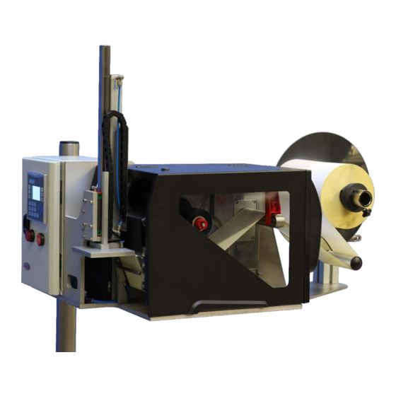
- Page 1 AG3000T USER MANUAL AG3000T AG3000T-LS AG3000T (print & apply system) with optional label unwinder User Manual: AG3000T Version: 1.0 Issue Date: May 2016...
-
Page 2: Table Of Contents
Installing the internal rewinder in the printer ................. 17 Installing the applicator interface ....................19 Integrating the printer and applicator unit ..................21 Operating your AG3000T(-LS) ........................26 Print & apply cycle: the basics ......................26 Printer configuration for applicator use ................... 26 6.2.1 Power on the printer ........................ - Page 3 5.3.2 Checking the mechanical settings (!) ....................29 5.3.3 Run a test cycle ..........................31 5.3.4 The “START” menu ......................... 31 5.3.5 The “SERVIS1” menu ........................33 5.3.6 The “MANUAL” menu ........................33 5.3.7 The “LANGUAGE” menu ......................... 34 Mechanical and pneumatic adjustments ....................35 Manual menu ...........................
-
Page 4: Introduction
1. Introduction 1.1 Overview Godex AG3000 print & apply systems match ZX1000i printers, either with 203, 300 or 600dpi print resolution, with high end, air-driven tamp applicators with the purpose of print and apply labels on demand. AG3000 print & apply systems are available as easy to install, ready-to-use solutions, but you can also configure your own customized systems by combining the components in a different way. -
Page 5: Basic Safety Precautions
AG3000 systems. They do however not replace any safety instruction published in separate Godex ZX1(X)00i user- and service manuals, and must be considered complementary to those instead. -
Page 6: Occupational Health And Safety Rules
• Storage ambient non-condensing relative air humidity within the range of 20% to 85% RH Occupational health and safety rules The device contains moving parts that can pose a risk to the operator unless the safety rules are adhered to. In order to prevent a potential injury, read the following safety rules carefully: •... -
Page 7: Never
Never: • Connect the device to a source of electric power if any of the protective parts (electric component covers, safety labelling and/or safety elements of the device) have been removed and/or damaged. • Modify the mechanical design and/or electrical circuitry of the device in any way. •... -
Page 8: The Possible Risks Of Electric Shocks If Working With The Applicator
The possible risks of electric shocks if working with the applicator Despite the application device being manufactured in accordance with relevant technical regulations pertaining to safety, its technical design cannot preclude all risks that may occur, especially in the event of careless or negligent behavior during use of the device. The device must be used with full awareness of the following risks of electric shock: •... -
Page 9: Contents Of Delivery - What's In The Box
3.2.1 Box 1: Printer + Accessories If you have received the printer parts for your AG3000 directly from a Godex subsidiary the printer box contains the printer components described below here. In case you have purchased the printer and options through a Godex distributor or dealer you may receive them in separate boxes. - Page 10 • 1x GoDEX ZX1(X)00i applicator interface, item no. GP-031-Z2i003-001: • 1x GoDEX ZX1(X00i) peeler/rewinder unit, item no. GP-031-Z21005-000...
-
Page 11: Box 2: Applicator Components
3.2.2 Box 2: Applicator components A- Parts to build heavy duty floor stand item AG-2000-123322 D- Control Unit C- Applicator machine clamp B-From left to right: Positioner (AG-2000-110110) (AG-2000-110108) 700mm tube (AG-2000-110112) 90° clamp for use with positioner (AG-110106) - Page 12 E- AG3000T applicator base plate, piston, mounting material, applicator head. (Item AG-3000-110060, AG-3000-110100, AG-3000-22L060, or AG-3000-22L100)
-
Page 13: Assembling The System
Assembling the system Required Tools • H ex wrenches 4, 5, 6, 8 • S ocket wrench 15 • S crewdriver set • Ph illips head screwdriver set Assembling the stand Please preview all steps and parts described below here before you start assembling. It will help you to anticipate on every step to come. - Page 14 Picture 6: the height of each foot is adjustable to level the stand on uneven surfaces Picture 7: close the ends of the alloy profiles with the black plastic covers Pic. 6 Pic. 7 Picture 8: place the shorter alloy leg (the one with holes on two faces) between the longer legs.
- Page 15 Picture 11 - 13: take the remaining profile (pic. 11) and mount it firmly onto the central leg: Pic. 11 Pic. 12 Pic. 13 Picture 14 - 16: mount the adapter plate and clamp on the top of the vertical profile. Pic.
- Page 16 Picture 19-20: mount clamp 110106 onto the slide inside positioner 110110 and then mount the positioner on the upper end of the 700mm tube: POSITIONER AG-2000-110110 CLAMP AG-2000-110106 Pic. 19 Pic. 20 Picture 21: at a later stage the end of the horizontal positioner must be inserted in- and firmly attached to clamp 110108, which is pre-mounted on the applicator unit: Pic.
-
Page 17: Installing The Internal Rewinder In The Printer
Installing the internal rewinder in the printer Picture 1: Step 1. Open the main printer cover Step 2. Remove the three screws holding the left side cover Step 3. Remove the lower front cover Step 4. Remove the plug from the center plate (The rewinder bearings will be inserted here) Picture 2: Step 5. - Page 18 Picture 4: Step 7. Insert the second bearing from the left sight Picture 5: Step 8. SKIP this step! Not relevant for applicator use Step 9. SKIP this step! Not relevant for applicator use. Step 10. Install the diverter pulley Step 11.
-
Page 19: Installing The Applicator Interface
Installing the applicator interface The GoDEX ZX1X00i applicator interface can be used with both 24V and 5V peripheral systems, both in terms of power supply and in- and outgoing signals. Hence, the correct voltage levels of the in- and outgoing signals must be configured before installation in the printer. Even in case the... - Page 20 Picture 3 and 4: remove this cover on the back of the printer Pic. 3 Pic. 4 Picture 5 and 6: connect the applicator interface to the socket on the mainboard: Pic. 5 Pic. 6...
- Page 21 Picture 7 + 8: place the external connector in the slot and tighten the screws from outside Pic. 7 Pic. 8 Picture 9 - 11: remount the left printer cover:...
-
Page 22: Integrating The Printer And Applicator Unit
Integrating the printer and applicator unit After installing the internal rewinder and applicator interface it is time to mount the printer on the applicator. You do this by following the steps showed in the following pictures. Picture 1: unscrew the screws indicated with “1” and remove the printer’s back cover Picture 2: unscrew the screws indicated with “2”... - Page 23 Picture 4: • Remove the tie wraps (4) • Move the slide (5) as far as possible towards the applicator head (A) • Lift up the piston (B) including the slide and tubes and place the slide (5) against surface “6” Pic.
- Page 24 Picture 7: place the prepared printer onto adapter plate “C” and main frame “D” Pic. 7 Picture 8: mount the printer E on main frame D with 6x M4x16 and tighten properly (step 10) Pic. 8...
- Page 25 Picture 9: • Connect the I/O interface cable coming from the control box to the printer’s applicator port (step 11) • Connect the power cable coming from the control box to the printer (step 12) Picture 10: • Remount the rear printer cover (step 13 - not applicable if you install the optional label unwind stand) Picture 11 (optional): •...
-
Page 26: Operating Your Ag3000T(-Ls)
Operating your AG3000T(-LS) Print & apply cycle: the basics The labelling cycle is initiated by the START signal, given by the applicator control box. The cycle can only begin if the buffer memory of the printer is provided with data, the printer READY signal to the applicator is on and the applicator operating status is RUN. -
Page 27: Firmware
5.2.2 Firmware The recommended firmware version for applicator usage is V2.Y06 (April 2016). Please always verify with your supplier or directly with GoDEX whether updates have been released. The current supportive display firmware is 2.003 (April 2016). 5.2.3 Setting the printer in applicator mode Set and lock the applicator mode in the printer menu to enable correct and reliable communication between the applicator control unit and the printer. - Page 28 Pic. 7: select the icon shown below) to return to main menu Pic. 8: Back on main menu...
-
Page 29: Formatting The Applicator Interface (!)
5.2.4 Formatting the applicator interface (!) It is necessary to format the applicator interface by sending the command ^XSET,APPLICATOR,0,1 to the printer. For more details, please see the printer manual. 5.2.5 Smart backfeed The smart backfeed function is currently (April 2016) not supported in applicator mode. 5.2.6 Create a label and load media Now create a label and store it on the printer. - Page 30 Please perform the following procedure: Picture 1 & 2: Check the alignment of the application head (A) and the printer peeler edge (B). • The horizontal distance between applicator head and peeler edge (1) must be 0,5mm to 1mm. • The applicator head and the peeler edge must be aligned perfectly parallel to each other •...
-
Page 31: Run A Test Cycle
5.3.3 Run a test cycle After verifying the applicator and printer have been aligned properly (see § 5.3.2) and after the printer has received the print data (see § 5.2.6) you can run a test cycle. The system must be in “START”... - Page 32 Image 2: By pushing the START-button on the control unit you will bring the applicator from “STOP” into “RUN” mode if: • There does not occur an error in the applicator • There does not occur an error in the printer the screen will display “RUN”...
-
Page 33: The "Servis1" Menu
5.3.5 The “SERVIS1” menu Image 1: in this menu you set 2 key parameters. Down The time in seconds during which the applicator head travels and remains down before returning to its starting position. In workflows in which objects of various sizes are handled simultaneously this value must be adjusted to the objects that require the longest travelling time. -
Page 34: The "Language" Menu
Select “3” to check whether the cylinder receives enough air pressure to go down and up. Select “4” to check printer output (the printer will print one label if the input buffer is loaded) You exit this menu with either the LEFT arrow (back to the SERVIS1 menu), the DOWN arrow (further to the language settings) or the START button (back to the START menu). -
Page 35: Mechanical And Pneumatic Adjustments
6. Mechanical and pneumatic adjustments 6.1 Manual menu You must first open the “MANUAL” menu to adjust mechanical settings on the applicator: • Bring the device in stop mode • Press the “DOWN” arrow whilst the device is in “STOP” mode to open the “SERVIS 1 menu”, confirm the preselected settings with “ENTER”... - Page 36 Pictures 2. Picture 3...
-
Page 37: Height Adjustment
6.2.1 Height adjustment 1) Note the distance in mm the applicator head start position is too low or too high 2) Bring the applicator head in its lowest possible position by selecting “3” on the keypad 3) Remove screws (A) and remove the applicator head (B) 4) Loosen locknut (C) against nut (D) 5) Hold piston rod (E) and rotate nut (D) to move the applicator head bracket in the desired direction 6/ tighten locknut (C) with the applicator bracket in the new position... -
Page 38: Air Settings I: Blowing
6.3 Air settings i: blowing In case the label is not transferred to the applicator head properly and tends to fall down there may be too little air flowing through the nozzles underneath the labels or the direction of the airflow is faulty. -
Page 39: Air Settings Ii: Vacuum
6.4 Air settings ii: vacuum The applicator creates a vacuum which sucks the label towards the bottom of the applicator head during its transfer from the printer to the applicator and which keeps it there whilst travelling towards the product. To properly distribute the sucking power, the applicator head contains grooves over all of its surface. -
Page 40: Connecting To Auxiliary Systems
The AG3000 applicator can be integrated in any hard- and software environment as long as the GoDEX ZX1X00i printer is compatible with that environment as well. However, the communication lines between the printer and any auxiliary system and between the applicator and such system are fully separated. -
Page 41: Triggering Devices - Input Signals
In case of an application time out or printer error, switch X1-6/X1-7 will be closed (ON). If the AG3000T is ready for the next print & apply cycle switch X1-8/X1-9 will be closed (ON). See both picture 1 on this page and picture 1 on the previous page for a visualization. -
Page 42: Options
Contact us or your GoDEX equipment supplier for more detailed information regarding the options listed here and in case you are not sure the AG3000T(-LS) is the right solution for your application. Maintenance AG3000T(-LS) systems require hardly any maintenance, which goes for both the printer and the applicator components. -
Page 43: Wire Diagrams
10 Wire diagrams 10.1 Power and signals schematic 10.2 Control unit picture... -
Page 44: Power Circuits
10.3 Power circuits 10.4 Connector rack - detailed view... -
Page 45: Connector Rack Diagram
10.5 Connector rack diagram... -
Page 46: Electro-Pneumatic Diagram
10.6 Electro-pneumatic diagram 10.6 PLC / Printer applicator port diagram...
Need help?
Do you have a question about the AG3000T and is the answer not in the manual?
Questions and answers