Siemens SIMATIC S7-400H System Manual
Fault-tolerant systems
Hide thumbs
Also See for SIMATIC S7-400H:
- System manual (504 pages) ,
- Manual (337 pages) ,
- Manual (5 pages)
Table of Contents
Advertisement
SIMATIC Fault-tolerant Systems S7-400H
SIMATIC
Fault-tolerant Systems
S7-400H
System Manual
09/2007
A5E00267695-03
Preface
______________
Fault-tolerant automation
systems
______________
______________
S7-400H installation options
______________
Getting started
______________
Installation of a CPU 41x–H
Special functions of a
______________
CPU 41x-H
S7–400H in PROFIBUS DP
______________
mode
System and operating states
______________
of the S7–400H
______________
Link-up and update
______________
Using I/Os in S7–400H
______________
Communication
______________
Configuring with STEP 7
Failure and replacement of
______________
components during operation
System modifications in
______________
operation
______________
Synchronization modules
S7-400 cycle and reaction
______________
times
______________
Technical data
Characteristic values of
______________
redundant automation
systems
1
2
3
4
5
6
7
8
9
10
11
12
13
14
15
16
17
A
Advertisement
Table of Contents

Related Manuals for Siemens SIMATIC S7-400H


Summary of Contents for Siemens SIMATIC S7-400H
- Page 1 Preface ______________ Fault-tolerant automation SIMATIC Fault-tolerant Systems S7-400H systems ______________ ______________ S7-400H installation options SIMATIC ______________ Getting started ______________ Installation of a CPU 41x–H Fault-tolerant Systems Special functions of a S7-400H ______________ CPU 41x-H S7–400H in PROFIBUS DP ______________ mode System and operating states System Manual ______________...
- Page 2 Trademarks All names identified by ® are registered trademarks of the Siemens AG. The remaining trademarks in this publication may be trademarks whose use by third parties for their own purposes could violate the rights of the owner.
-
Page 3: Table Of Contents
Table of contents Preface ..............................15 Preface............................15 Fault-tolerant automation systems......................21 Redundant automation systems in the SIMATIC series ..............21 Increasing system availability ......................23 S7-400H installation options ........................25 S7-400H installation options ......................25 Rules for the assembly of fault-tolerant stations................27 The S7-400H base system ......................28 I/O modules for S7-400H ......................30 Communication ..........................31 Tools for configuration and programming ..................31... - Page 4 Table of contents Special functions of a CPU 41x-H......................61 Updating the firmware without a memory card ................61 Firmware update in RUN mode ....................63 Reading service data ........................64 S7-400H in PROFIBUS DP mode......................65 CPU 41x–H as PROFIBUS DP master ..................65 7.1.1 DP address areas of 41xH CPUs ....................
- Page 5 Table of contents Using I/Os in S7-400H ........................... 119 10.1 Using I/Os in S7-400H .......................119 10.2 Introduction ..........................119 10.3 Using single-channel, one-sided I/Os ..................121 10.4 Using single-channel switched I/Os ...................123 10.5 Connecting redundant I/Os ......................127 10.5.1 Evaluating the passivation status ....................149 10.6 Other options for connecting redundant I/Os................151 Communication............................
- Page 6 Table of contents 13.3 Failure and replacement of components of the distributed I/Os ..........196 13.3.1 Failure and replacement of a PROFIBUS-DP master .............. 196 13.3.2 Failure and replacement of a redundant PROFIBUS-DP interface module ......197 13.3.3 Failure and replacement of a PROFIBUS-DP slave ..............197 13.3.4 Failure and replacement of PROFIBUS-DP cables ..............
- Page 7 Table of contents 14.8 Changing the CPU memory configuration .................239 14.8.1 Changing the CPU memory configuration .................239 14.8.2 Expanding load memory ......................239 14.8.3 Changing the type of load memory ....................240 14.9 Reconfiguration of a module ......................243 14.9.1 Reconfiguration of a module ......................243 14.9.2 Step A: Editing parameters offline .....................244 14.9.3...
- Page 8 Table of contents Differences between fault-tolerant systems and standard systems............329 Function modules and communication processors supported by the S7-400H........333 Connection examples for redundant I/Os....................335 SM 321; DI 16 x DC 24 V, 6ES7 321–1BH02–0AA0 ..............335 SM 321; DI 32 x DC 24 V, 6ES7 321–1BL00–0AA0..............337 SM 321;...
- Page 9 Table of contents Tables Table 5-1 LEDs on the CPUs........................41 Table 5-2 Mode selector switch settings ......................49 Table 5-3 Levels of protection of a CPU ......................50 Table 5-4 Types of memory card .........................55 Table 7-1 41x CPUs, MPI/DP interface as PROFIBUS DP .................66 Table 7-2 Meaning of the "BUSF"...
- Page 10 Table of contents Table 16-5 Portion of the process image transfer time, CPU 417-4H............264 Table 16-6 Extension of the cycle time ....................... 264 Table 16-7 Operating system execution time at the scan cycle checkpoint ..........265 Table 16-8 Cycle time extension due to nested interrupts ................265 Table 16-9 Direct access of the CPUs to I/O modules................
- Page 11 Table of contents Figure 9-4 Meanings of the times relevant for updates................107 Figure 9-5 Correlation between the minimum I/O hold time and the maximum disable time for priority classes > 15 ..........................110 Figure 10-1 Single-channel, switched ET 200M distributed I/O ..............124 Figure 10-2 Redundant I/O in central and expansion units................127 Figure 10-3...
- Page 12 Table of contents Figure 16-3 Minimum cycle time........................267 Figure 16-4 Formula: Influence of communication load ................268 Figure 16-5 Distribution of a time slice ......................268 Figure 16-6 Dependency of the cycle time on the communication load............269 Figure 16-7 DP cycle times on the PROFIBUS DP network ................
-
Page 13: S7-400H
Table of contents Figure F-25 Example of an interconnection with SM 331; AI 8 x 12 bit ............360 Figure F-26 Example of an interconnection with SM 331; AI 8 x 16 bit ............361 Figure F-27 Interconnection example 1 SM 331; AI 8 x 0/4...20 mA HART..........362 Figure F-28 Interconnection example 2 SM 331;... - Page 14 Table of contents S7-400H System Manual, 09/2007, A5E00267695-03...
-
Page 15: Preface
Preface Preface Purpose of the manual This manual represents a useful reference and contains information on operating options, functions and technical specifications of the S7-400H CPUs. For information on installing and wiring those and other modules to install an S7-400H S7-400 Programmable Controllers, Installation system, refer to the manual. - Page 16 Preface 1.1 Preface Versions required or order numbers of essential system components System component Version required or order number External master on PROFIBUS DP Order no. 6GK7 443–5DX03–0XE0 hardware version 1 or higher, and firmware CP443-5 Extended version 5.1.4 or higher Order no.
- Page 17 If you have any questions relating to the products described in this manual, and do not find the answers in this documentation, please contact your Siemens partner at our local offices. You will find information on who to contact at: http://www.siemens.com/automation/partner...
- Page 18 Phone: +49 (911) 895-4759 Fax: +49 (911) 895-5193 E-mail: hf-cc.aud@siemens.com Training center We offer a range of courses to help you to get started with the SIMATIC S7 automation system. Please contact your regional Training Center, or the Central Training Center in Nuremberg, 90327 Germany.
- Page 19 Service & Support on the Internet In addition to the information in our documentation, you can also access our knowledge base online at: http://www.siemens.com/automation/service&support There you will find: ● The newsletter, which constantly provides you with up-to-date information on your products.
- Page 20 Preface 1.1 Preface S7-400H System Manual, 09/2007, A5E00267695-03...
-
Page 21: Fault-Tolerant Automation Systems
Fault-tolerant automation systems Redundant automation systems in the SIMATIC series Operating objectives of redundant automation systems Redundant automation systems are used in practice with the aim of achieving a higher degree of availability or fault tolerance. Figure 2-1 Operating objectives of redundant automation systems Note the difference between fault-tolerant and fail-safe systems.An S7-400H is a fault-tolerant automation system that may only be used to control safety-relevant processes in conjunction with additional measures. - Page 22 Fault-tolerant automation systems 2.1 Redundant automation systems in the SIMATIC series Software redundancy For many applications, the requirements for redundancy quality or the extent of plant sections that may require redundant automation systems do not necessarily justify the implementation of a special fault-tolerant system. Usually, simple software mechanisms are adequate to allow a failed control task to be continued on a substitute system if a problem occurs.
-
Page 23: Increasing System Availability
Fault-tolerant automation systems 2.2 Increasing system availability Increasing system availability The S7-400H automation system satisfies the high demands on availability, intelligence and distribution put on state-of-the-art automation systems. The system provides all functionality required for the acquisition and preparation of process data, including functions for the open-loop and closed-loop control and monitoring of assemblies and plants. -
Page 24: Figure 2-3 Example Of Redundancy In A Network Without An Error Or Fault
Fault-tolerant automation systems 2.2 Increasing system availability Redundancy nodes Redundant nodes represent the reliability of systems with redundant components in case of failure. A redundant node can be considered as independent when the failure of a component within the node does not result in reliability constraints in other nodes or in the entire system. The availability of the entire system can be illustrated simply based on a block diagram. -
Page 25: S7-400H Installation Options
S7-400H installation options S7-400H installation options The first part of the description deals with the basic configuration of the redundant S7-400H automation system, and with the components of an S7-400H base system. We then set out the hardware components with which you can expand this base system. The second part deals with the software tools which you are going to use to configure and program the S7-400H. -
Page 26: Figure 3-1 Overview
S7-400H installation options 3.1 S7-400H installation options The following figure shows an example of an S7-400H configuration with shared distributed I/O and connection to a redundant plant bus. The next pages deal with the hardware and software components required for the installation and operation of the S7-400H. Figure 3-1 Overview Further information... -
Page 27: Rules For The Assembly Of Fault-Tolerant Stations
S7-400H installation options 3.2 Rules for the assembly of fault-tolerant stations Rules for the assembly of fault-tolerant stations The following rules have to be complied with for a fault-tolerant station, in addition to the rules that generally apply to the arrangement of modules in the S7-400: ●... -
Page 28: The S7-400H Base System
S7-400H installation options 3.3 The S7-400H base system The S7-400H base system Hardware of the base system The base system consists of the hardware components required for a fault-tolerant control. The following figure shows the components in the configuration. The base system may be expanded with the standard modules of an S7-400. Restrictions only apply to the function and communications modules;... - Page 29 S7-400H installation options 3.3 The S7-400H base system Power supply You require one power supply module from the standard range of the S7-400 for each fault-tolerant CPU, or to be more precise, for each of the two subsystems of the S7-400H. The power supply modules available have rated input voltages of 24 V DC and 120/230 V AC, at an output current of 10 and 20 A.
-
Page 30: I/O Modules For S7-400H
S7-400H installation options 3.4 I/O modules for S7-400H I/O modules for S7-400H The S7-400H can be equipped with I/O modules of the SIMATIC S7 series. The I/Os can be used in the following devices: ● Central devices ● Expansion devices ●... -
Page 31: Communication
S7-400H installation options 3.5 Communication Communication The S7-400H supports the following communication methods and mechanisms: ● System buses with Industrial Ethernet ● Point-to-point connection This equally applies to the central and distributed components you can use. Suitable communication modules are listed in appendix E. Communication availability You can vary the availability of communication with the S7-400H. -
Page 32: The User Program
S7-400H installation options 3.7 The user program The user program The rules of designing and programming a standard S7-400 system also apply to the S7-400H. In terms of user program execution, the S7-400H behaves in exactly the same manner as a standard system. -
Page 33: Documentation
S7-400H installation options 3.8 Documentation Documentation The diagram below provides an overview of the descriptions of the various components and options in the S7-400H automation system. Figure 3-3 User documentation for fault-tolerant systems S7-400H System Manual, 09/2007, A5E00267695-03... - Page 34 S7-400H installation options 3.8 Documentation S7-400H System Manual, 09/2007, A5E00267695-03...
-
Page 35: Getting Started
Getting started Getting started This guide walks you through the steps that have to be performed to commission the system, based on a specific example. and results in a working application. You will learn how an S7-400H programmable logic controller operates and become familiar with its response to a fault. -
Page 36: Hardware Installation And S7-400H Commissioning
Getting started 4.3 Hardware installation and S7-400H commissioning Hardware installation and S7-400H commissioning Installing Hardware To install the S7-400H as shown in Figure 4-1: Figure 4-1 Hardware installation 1. Install both modules of the S7-400H automation system as described in the S7-400 Automation Systems, Installation Module Specifications manuals. - Page 37 Getting started 4.3 Hardware installation and S7-400H commissioning Commissioning the S7-400H Follow the steps outlined below to commission the S7-400H: 1. In SIMATIC Manager, open the sample project "HProject". The configuration corresponds to the hardware configuration described in "Requirements". 2. Open the hardware configuration of the project by selecting the hardware object, right-clicking, and selecting the context menu command "Object ->...
-
Page 38: Examples Of The Reaction Of The Fault-Tolerant System To Faults
Getting started 4.4 Examples of the reaction of the fault-tolerant system to faults Examples of the reaction of the fault-tolerant system to faults Example 1: Failure of a CPU or of a power supply module Initial situation: The S7-400H is in redundant mode. 1. -
Page 39: Installation Of A Cpu 41X-H
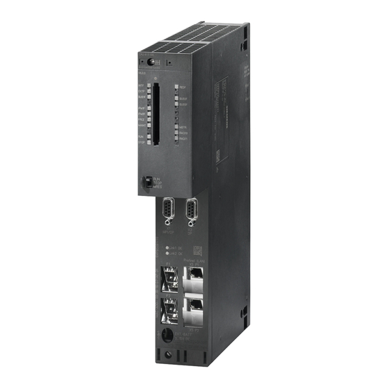
Installation of a CPU 41x–H Control and display elements of the CPUs Operator controls and displays on the CPU 412-3H MPI/DP EXT.-BATT 5...15 V DC Figure 5-1 Arrangement of the operator controls and displays on the CPU 412-3H S7-400H System Manual, 09/2007, A5E00267695-03... -
Page 40: Figure 5-2 Layout Of The Control And Display Elements Of The Cpu 414-4H/417-4H
Installation of a CPU 41x–H 5.1 Control and display elements of the CPUs Control and display elements of CPU 414–4H/417–4H MPI/DP EXT.-BATT 5...15 V DC Figure 5-2 Layout of the control and display elements of the CPU 414-4H/417-4H S7-400H System Manual, 09/2007, A5E00267695-03... -
Page 41: Table 5-1 Leds On The Cpus
Installation of a CPU 41x–H 5.1 Control and display elements of the CPUs LED displays The following shows you an overview of the LEDs on the individual CPUs. Sections Monitoring functions of the CPU (Page 44) and Status and error displays (Page 46) describe the states and errors/faults indicated by these LEDs. - Page 42 Installation of a CPU 41x–H 5.1 Control and display elements of the CPUs Slot for interface modules You can insert an H-Sync module in this slot. MPI/DP interface You can, for example, connect the following devices to the MPI interface of the CPU: ●...
-
Page 43: Figure 5-3 Jack
Installation of a CPU 41x–H 5.1 Control and display elements of the CPUs To connect an auxiliary voltage to the "EXT. BATT" input, you require a cable with a 2.5 mm ∅ plug as shown in the figure below. Observe the polarity of the jack. Figure 5-3 Jack You can order a jack plug with an assembled cable from the using order number... -
Page 44: Monitoring Functions Of The Cpu
Installation of a CPU 41x–H 5.2 Monitoring functions of the CPU Monitoring functions of the CPU Monitoring functions and error messages The hardware and operating system of the CPU provide monitoring functions to ensure proper operation and defined reactions to errors. Various errors may also trigger a reaction in the user program. - Page 45 Installation of a CPU 41x–H 5.2 Monitoring functions of the CPU Error class Cause of error Reaction of the operating system Error LED Priority class is called, but the Program • Call of OB 85 INTF corresponding OB is not available. execution error If the OB is not loaded: CPU goes into In the case of an SFB call: missing or...
-
Page 46: Status And Error Displays
Installation of a CPU 41x–H 5.3 Status and error displays Status and error displays RUN and STOP LEDs The RUN and STOP LEDs provide information about the active CPU operating status. Meaning STOP CPU is in RUN mode. CPU is in STOP mode. The user program is not executed. Cold restart/warm restart is possible. - Page 47 Installation of a CPU 41x–H 5.3 Status and error displays INTF, EXTF and FRCE LEDs The three LEDs, INTF, EXTF and FRCE, provide information about errors and special events in user program execution. Meaning INTF EXTF FRCE An internal error was detected (programming or parameter assignment error).
- Page 48 Installation of a CPU 41x–H 5.3 Status and error displays REDF LED The REDF LED indicates specific system states and redundancy errors. REDF LED System state Constraints Link-up 0.5 Hz Update 2 Hz Redundant (CPUs are redundant) No redundancy error Redundant (CPUs are redundant) There is an I/O redundancy error: Failure of a DP master, or partial or total...
-
Page 49: Mode Selector Switch
Installation of a CPU 41x–H 5.4 Mode selector switch Mode selector switch Function of the mode selector switch This switch can be used to set the CPU to RUN and STOP modes, or to reset the CPU memory. STEP 7 offers further options of changing the mode. Positions The mode selector switch is a rocker switch. -
Page 50: Security Levels
Installation of a CPU 41x–H 5.5 Security levels Security levels You can define a security level for your project in order to prevent unauthorized access to the CPU programs. The objective of these security settings is to grant a user access to specific programming device functions which are not protected by password, and to allow that user to execute those functions on the CPU. -
Page 51: Operating Sequence For Memory Reset
Installation of a CPU 41x–H 5.6 Operating sequence for memory reset Operating sequence for memory reset Case A: You want to download a new user program to the CPU 1. Set the switch to the STOP position. Result: The STOP LED lights. 2. - Page 52 Installation of a CPU 41x–H 5.6 Operating sequence for memory reset Data retained after a memory reset... The following values are retained after a memory reset: ● The content of the diagnostics buffer If you had not inserted a flash card during memory reset, the CPU resets the capacity of the diagnostics buffer to its default setting of 120 entries, i.e.
- Page 53 Installation of a CPU 41x–H 5.6 Operating sequence for memory reset Operating sequence for restart t/warm restart 1. Set the switch to the STOP position. Result: The STOP LED lights. 2. Set the switch to the RUN position. Result: The STOP LED goes out, the RUN LED is lit. Whether the CPU performs a cold start or a hot restart is determined by its configuration.
-
Page 54: Structure And Functions Of The Memory Cards
Installation of a CPU 41x–H 5.7 Structure and Functions of the Memory Cards Structure and Functions of the Memory Cards Order numbers The order numbers for memory cards are listed in the technical specifications, see section Technical specifications of the memory cards (Page 309). Design of a memory card The size of a memory card corresponds to that of a PCMCIA card. -
Page 55: Table 5-4 Types Of Memory Card
Installation of a CPU 41x–H 5.7 Structure and Functions of the Memory Cards What type of memory card to use? Whether you use a RAM card or a Flash card depends on your application. Table 5-4 Types of memory card If you ... - Page 56 Installation of a CPU 41x–H 5.7 Structure and Functions of the Memory Cards What memory card capacity to use? The capacity of your memory card is determined by the scope of the user program. Determining memory requirements using SIMATIC Manager You can view the block lengths offline by selecting the "Properties - Block folder offline"...
-
Page 57: Multipoint Interface (Mpi)
Installation of a CPU 41x–H 5.8 Multipoint interface (MPI) Multipoint interface (MPI) Connectable devices You can, for example, connect the following nodes to the MPI: ● Programming devices (PG/PC) ● Operating and monitoring devices (OPs and TDs) ● Additional SIMATIC S7 PLCs Various compatible devices take the 24 V supply from the interface. -
Page 58: Profibus Dp Interface
Installation of a CPU 41x–H 5.9 PROFIBUS DP interface PROFIBUS DP interface Connectable devices You can connect any slave conforming to the DP standard to the PROFIBUS DP interface. Here, the CPU represents the DP master, and is connected to the passive slave stations or, in stand-alone mode, to other DP masters via the PROFIBUS DP field bus. -
Page 59: Overview Of The Parameters For The S7-400H Cpus
Installation of a CPU 41x–H 5.10 Overview of the parameters for the S7-400H CPUs 5.10 Overview of the parameters for the S7-400H CPUs Default values You can determine the CPU-specific default values by selecting "Configuring Hardware" in STEP 7. Parameter blocks The reactions and properties of the CPU are set at the parameters which are stored in system data blocks. - Page 60 Installation of a CPU 41x–H 5.10 Overview of the parameters for the S7-400H CPUs Parameter assignment tool You can set the individual CPU parameters using "HW Config" in STEP 7. Note When you modify the parameters listed below, the operating system initializes the following values: ●...
-
Page 61: Special Functions Of A Cpu 41X-H
Special functions of a CPU 41x-H Updating the firmware without a memory card Basic procedure To update the firmware of a CPU, you will receive several files (*.UPD) containing the current firmware. Download these files to the CPU. You do not need a memory card to perform an online update. - Page 62 Special functions of a CPU 41x-H 6.1 Updating the firmware without a memory card Procedure Proceed as follows to update the firmware of a CPU: 1. Open the station containing the CPU you want to update in HW Config. 2. Select the CPU. 3.
-
Page 63: Firmware Update In Run Mode
Special functions of a CPU 41x-H 6.2 Firmware update in RUN mode Firmware update in RUN mode Requirement The size of the load memory on the master and standby CPU is the same. Both sync links exist and are working. Procedure Follow the steps below to update the firmware of the CPUs of an H system in RUN: 1. -
Page 64: Reading Service Data
Special functions of a CPU 41x-H 6.3 Reading service data Reading service data Use case If you need to contact our Customer Support due to a service event, the department may require specific diagnostic information on the CPU status of your system. This information is stored in the diagnostic buffer and in the actual service data. -
Page 65: S7-400H In Profibus Dp Mode
PROFIBUS subnet, refer to the STEP 7 Online Help. Further information For details and information on migrating from PROFIBUS DP to PROFIBUS DPV1, refer to the Internet URL: http://support.automation.siemens.com under article number 7027576 S7-400H System Manual, 09/2007, A5E00267695-03... -
Page 66: Dp Address Areas Of 41Xh Cpus
S7-400H in PROFIBUS DP mode 7.1 CPU 41x–H as PROFIBUS DP master 7.1.1 DP address areas of 41xH CPUs Address areas of 41xH CPUs Table 7-1 41x CPUs, MPI/DP interface as PROFIBUS DP Address area 412-3H 414-4H 417–4H MPI interface as PROFIBUS DP, inputs and outputs (bytes) in each case 2048 2048 2048... - Page 67 "DPV1" in this context. The new version features various expansions and simplifications. SIEMENS automation components feature DPV1 functionality. In order to be able to use these new features, you first have to make some modifications to your system. A full description of the migration from IEC 61158 to DPV1 is available in the FAQ section titled "Migrating from IEC 61158 to DPV1", FAQ article ID 7027576, on the Customer Support...
- Page 68 You can also use DPV1 slaves without a conversion to DPV1. In this case they behave like conventional slaves. SIEMENS DPV1 slaves can be operated in S7-compatible mode. To integrate DPV1 slaves from other manufacturers, you need a GSD file complying with IEC 61158 earlier than revision 3.
-
Page 69: Diagnostics Of A 41Xh Cpu Operating As Profibus Dp Master
S7-400H in PROFIBUS DP mode 7.1 CPU 41x–H as PROFIBUS DP master 7.1.3 Diagnostics of a 41xH CPU operating as PROFIBUS DP master Diagnostics using LEDs The following table shows the meaning of the BUSF LED. The BUSF LED assigned to the interface configured as the PROFIBUS DP interface always lights up or flashes when a problem occurs. -
Page 70: Figure 7-1 Diagnostics With Cpu 41Xh
S7-400H in PROFIBUS DP mode 7.1 CPU 41x–H as PROFIBUS DP master Evaluating diagnostics data in the user program The figure below shows how to evaluate the diagnostics data in the user program. Figure 7-1 Diagnostics with CPU 41xH S7-400H System Manual, 09/2007, A5E00267695-03... -
Page 71: Table 7-4 Event Detection Of The Cpu 41Xh As A Dp Master
S7-400H in PROFIBUS DP mode 7.1 CPU 41x–H as PROFIBUS DP master Diagnostic addresses in connection with DP slave functionality Assign the diagnostics addresses for PROFIBUS DP at the 41xH CPU. Ensure during configuration that DP diagnostics addresses are assigned once to the DP master and once to the DP slave. - Page 72 S7-400H in PROFIBUS DP mode 7.1 CPU 41x–H as PROFIBUS DP master Evaluation in the user program The table below shows you how to evaluate RUN-STOP changes of the DP slave on the DP master. See previous table. On the DP master On the DP slave (CPU 41x) Example of diagnostic addresses: Example of diagnostic addresses:...
-
Page 73: Consistent Data
S7-400H in PROFIBUS DP mode 7.2 Consistent Data Consistent Data Data that belongs together in terms of its content and a process state written at a specific point in time is known as consistent data. In order to maintain data consistency, do not modify or update the data during their transfer. -
Page 74: Consistency Of Communication Blocks And Functions
S7-400H in PROFIBUS DP mode 7.2 Consistent Data 7.2.1 Consistency of communication blocks and functions Using S7-400 the communication data is not processed in the scan cycle checkpoint; instead, this data is processed in fixed time slices during the program cycle. The system can always process the data formats byte, word and dword consistently, i.e. -
Page 75: Reading Data Consistently From A Dp Standard Slave And Writing Consistently To A Dp Standard Slave
S7-400H in PROFIBUS DP mode 7.2 Consistent Data 7.2.4 Reading data consistently from a DP standard slave and writing consistently to a DP standard slave Reading data consistently from a DP standard slave using SFC 14 "DPRD_DAT" Use SFC 14 "DPRD_DAT", "read consistent data of a DP standard slave", to read consistent data from a DP standard slave. -
Page 76: Consistent Data Access Without Using Sfc 14 Or Sfc 15
S7-400H in PROFIBUS DP mode 7.2 Consistent Data 7.2.5 Consistent data access without using SFC 14 or SFC 15 Consistent data access > 4 bytes is also possible without using SFC 14 or SFC 15. The data area of a DP slave which is to be transferred consistently will be written to a process image partition. -
Page 77: Figure 7-3 Dp Slave Properties
S7-400H in PROFIBUS DP mode 7.2 Consistent Data Example: The example of the process image partition 3 "TPA 3" below shows a possible configuration in HW Config: ● TPA 3 at output: Those 50 bytes are stored consistently in process image partition 3 (pulldown list "Consistent over >... - Page 78 S7-400H in PROFIBUS DP mode 7.2 Consistent Data S7-400H System Manual, 09/2007, A5E00267695-03...
-
Page 79: System And Operating States Of The S7-400H
System and operating states of the S7-400H System and operating states of the S7-400H This chapter features an introduction to the subject of S7-400H fault-tolerant systems. You will learn the basic concepts that are used in describing how fault-tolerant systems operate. -
Page 80: Introduction
System and operating states of the S7-400H 8.2 Introduction Introduction The S7-400H consists of two redundant configured subsystems that are synchronized via fiber-optic cables. The two subsystems create a redundant automation system operating with a two-channel (1-of-2) structure based on the "active redundancy" principle. What does active redundancy mean? Active redundancy, commonly also referred to as functional redundancy, means that all redundant resources are constantly in operation and simultaneously involved in the execution... -
Page 81: Figure 8-1 Synchronizing The Subsystems
You create your program in the same way as for standard S7-400 CPUs. Event-driven synchronization The "event-driven synchronization" procedure patented by Siemens was used for the S7-400H. This procedure has proved itself in practice and has already been used for the S5-115H and S5-155H controllers. -
Page 82: The System States Of The S7-400H
System and operating states of the S7-400H 8.3 The system states of the S7-400H The system states of the S7-400H The system states of the S7-400H derive from the operating states of the two CPUs. The term "system state" is used as a simplified term which identifies the concurrent operating states of the two CPUs. -
Page 83: The Operating States Of The Cpus
System and operating states of the S7-400H 8.4 The operating states of the CPUs The operating states of the CPUs Operating states describe the behavior of the CPUs at any given point in time. Knowledge of the operating states of the CPUs is useful for programming startup, the test, and the error diagnostics. -
Page 84: Stop Operating State
System and operating states of the S7-400H 8.4 The operating states of the CPUs Explanation of the diagram Point Description After the power supply has been turned on, the two CPUs (CPU 0 and CPU 1) are in STOP mode. CPU 0 changes to STARTUP and executes OB 100 or OB 102 according to the startup mode;... -
Page 85: Startup Operating State
System and operating states of the S7-400H 8.4 The operating states of the CPUs 8.4.2 STARTUP operating state Except for the additions described below, the behavior of S7-400H CPUs in STARTUP corresponds to that of standard S7-400 CPUs. Startup modes The fault-tolerant CPUs distinguish between cold start and warm restart. -
Page 86: Run Operating State
System and operating states of the S7-400H 8.4 The operating states of the CPUs 8.4.4 RUN operating state Except for the additions described below, the behavior of S7-400H CPUs in RUN corresponds to that of standard S7-400 CPUs. The user program is executed by at least one of the two CPUs in the following system states: ●... -
Page 87: Hold Operating State
System and operating states of the S7-400H 8.4 The operating states of the CPUs 8.4.5 HOLD operating state Except for the additions described below, the behavior of the S7-400H CPU in HOLD corresponds to that of a standard S7-400 CPU. The HOLD state has an exceptional role, as it is used only for test purposes. - Page 88 System and operating states of the S7-400H 8.4 The operating states of the CPUs 4. When a multiple-bit error occurs on only one of the redundant CPUs, that CPU will enter the TROUBLESHOOTING state. The partner CPU assumes master mode as required, and continues operation in single mode.
-
Page 89: Self-Test
System and operating states of the S7-400H 8.5 Self-test Self-test Processing the self-test The CPU executes the complete self-test program after POWER ON without backup, such as POWER ON after initial insertion of the CPU or POWER ON with no backup battery, and in the TROUBLESHOOTING state. -
Page 90: Table 8-4 Reaction To A Recurring Comparison Error
System and operating states of the S7-400H 8.5 Self-test RAM/PIO comparison error If the self-test returns a RAM/PIO comparison error, the fault-tolerant system quits redundant mode and the standby CPU enters the TROUBLESHOOTING state (in default configuration). The cause of the error is written to the diagnostics buffer. The reaction to a recurring RAM/PIO comparison error depends on whether the error occurs in the subsequent self-test cycle after troubleshooting or not until later. -
Page 91: Table 8-6 Hardware Fault With One-Sided Call Of Ob 121, Checksum Error, Second Occurrence
System and operating states of the S7-400H 8.5 Self-test Hardware fault with one-sided call of OB 121, checksum error, second occurrence A 41x-4H CPU reacts to a second occurrence of a hardware fault with a one-sided call of OB 121 and to checksum errors as set out in the table below, based on the various operating modes of the 41x-4H CPU. -
Page 92: Time-Based Reaction
System and operating states of the S7-400H 8.6 Time-based reaction Time-based reaction Instruction run times You will find the execution times of the STEP 7 instructions in the operation list for the S7-400 CPUs. Processing I/O direct access Please note that any I/O access always requires a synchronization of the two units, and so extends the cycle time. -
Page 93: Link-Up And Update
Link-up and update Effects of link-up and updating Link-up and updating are indicated by the REDF LEDs on the two CPUs. During link-up, the LEDs flash at a frequency of 0.5 Hz, and when updating at a frequency of 2 Hz. Link-up and update have various effects on user program execution and on communication functions. -
Page 94: Conditions For Link-Up And Update
Link-up and update 9.2 Conditions for link-up and update Conditions for link-up and update Which commands you can use on the PG to initiate a link-up and update operation is determined by the conditions on the master and standby CPU. The table below shows the correlation between those conditions and available PG commands for link-up and update operations. -
Page 95: Link-Up And Update
Link-up and update 9.3 Link-up and update Link-up and update There are two types of link-up and update operation: ● Within a "normal" link-up and update operation, the fault-tolerant system should change over from single mode to redundant mode. The two CPUs then process the same program synchronized with each other. -
Page 96: Figure 9-1 Sequence Of Link-Up And Update
Link-up and update 9.3 Link-up and update Flow chart of the link-up and update operation The diagram below outlines the general sequence of the link-up and update. In the initial situation, the master is operating in single mode. In the figure, CPU 0 is assumed to be the master. -
Page 97: Figure 9-2 Update Sequence
Link-up and update 9.3 Link-up and update Figure 9-2 Update sequence S7-400H System Manual, 09/2007, A5E00267695-03... -
Page 98: Figure 9-3 Example Of Minimum Signal Duration Of An Input Signal During The Update
Link-up and update 9.3 Link-up and update Minimum duration of input signals during update Program execution is stopped for a certain time during the update (the sections below describe this in greater detail). To ensure that the CPU can reliably detect changes to input signals during the update, the following condition must be satisfied: Min. -
Page 99: Link-Up Sequence
Link-up and update 9.3 Link-up and update 9.3.1 Link-up sequence For the link-up, you need to decide whether to carry out a master/standby changeover, or whether to conclude the operation by setting the system to redundant state. Link-up with the objective of setting up system redundancy To exclude differences in the two subsystems, the master and the standby CPU run comparisons. - Page 100 Link-up and update 9.3 Link-up and update For information on the required steps, based on the scenarios described above (alteration of the hardware configuration, or of the type of memory for load memory), refer to section Failure and replacement of components during operation (Page 185). Note Event though you may not have modified the hardware configuration or the type of load memory on the standby CPU, a master/standby changeover is carried out and the previous...
-
Page 101: Update Sequence
Link-up and update 9.3 Link-up and update 9.3.2 Update sequence What happens during updating? The execution of communication functions and OBs is restricted section by section during updating. Likewise, all the dynamic data (content of the data blocks, timers, counters and memory markers) are transferred to the standby CPU. - Page 102 Link-up and update 9.3 Link-up and update 9. Transfer of outputs and of all data block contents modified again. Transfer of timers, counters, memory markers and inputs. Transfer of the diagnostics buffer. During this data synchronization, the system interrupts the clock pulse for cyclic interrupts, time-delay interrupts and S7 timers.
-
Page 103: Switch To Cpu With Modified Configuration Or Expanded Memory Configuration
Link-up and update 9.3 Link-up and update Communication functions and resulting jobs After it has received one of the jobs specified below, the CPU must in turn generate communication jobs and output them to other modules. These include, for example, jobs for reading or writing parameter data records from/to the distributed I/O. - Page 104 Link-up and update 9.3 Link-up and update The following components are transferred from the RAM of the master CPU to the standby CPU: ● Contents of all data blocks assigned the same interface time stamp in both load memories and having the attributes "read only" and "unlinked". ●...
-
Page 105: Disabling Link-Up And Update
Link-up and update 9.3 Link-up and update RAM and load memory During the link-up, the system transfers the user program blocks (OBs, FCs, FBs, DBs, SDBs) from load memory of the master to RAM on the standby CPU. Exception: If the load memory modules are FLASH cards, the system only transfers the blocks from work memory. -
Page 106: Time Monitoring
Link-up and update 9.4 Time monitoring Time monitoring Program execution is interrupted for a certain time during updating. This secton is relevant to you if this period is critical in your process. If this is the case, configure one of the monitoring times described below. - Page 107 Link-up and update 9.4 Time monitoring The monitoring start times are indicated in the highlighted boxes in Figure 9-2. These times expire when the system enters the redundant state or on a master/standby changeover, i.e. on the transition of the new master to RUN when the update is completed. The figure below provides an overview of the relevant update times.
-
Page 108: Time-Based Reaction
Link-up and update 9.4 Time monitoring 9.4.1 Time-based reaction Time-based reaction during link-up The influence of link-up operations on your plant control system should be kept to an absolute minimum. The current load on your automation system is therefore a decisive factor in the increase of link-up times. -
Page 109: Determining The Monitoring Times
Link-up and update 9.4 Time monitoring 9.4.2 Determining the monitoring times Determination using STEP 7 or formulas STEP 7 automatically calculates the monitoring times listed below for each new configuration. You can also calculate these times using the formulas and procedures described below. They are equivalent to the formulas provided in STEP 7. - Page 110 Link-up and update 9.4 Time monitoring Configuration of the monitoring times When configuring monitoring times, always make allowances for the following dependencies; conformity is checked by STEP 7: Max. cycle time extension > max. communication delay > (max. disable time for priority classes > 15) >...
- Page 111 Link-up and update 9.4 Time monitoring Calculating the maximum disable time for priority classes > 15 (T The maximum disable time for priority classes > 15 is determined by four main factors: ● As shown in Figure 8-2, all the contents of data blocks modified since the last copy to the standby CPU are transferred to the standby CPU again when the update is completed.
- Page 112 Link-up and update 9.4 Time monitoring 5. For each DP master system this results in (DP master system) = T - (2 x T ) [1] PROG DP_UM SLAVE_UM NOTICE If T (DP master system) < 0, stop the calculation here. Possible remedies are shown below the following example calculation.
- Page 113 Link-up and update 9.4 Time monitoring Example of the calculation of T In the next steps, we take an existing configuration and we define the maximum permitted time during an update during which the operating system does not execute any programs or update the I/O.
- Page 114 Link-up and update 9.4 Time monitoring Remedies if it is not possible to calculate T If no recommendation results from calculation of the maximum inhibit time for priority classes > 15, you can remedy this by taking various measures: ● Reduce the cyclic interrupt cycle of the configured cyclic interrupt. ●...
-
Page 115: Performance Values For Link-Up And Update
Link-up and update 9.4 Time monitoring 9.4.3 Performance values for link-up and update User program share T of the maximum inhibit time for priority classes > 15 P15_AWP The user program share T of the maximum inhibit time for priority classes > 15 can be P15_AWP calculated using the following formula: in ms = 0.7 x size of DBs in work memory in KB + 75... -
Page 116: Influences On Time-Based Reaction
Link-up and update 9.4 Time monitoring 9.4.4 Influences on time-based reaction The period during which no I/O updates take place is primarily determined by the following influencing factors: ● the number and size of data blocks modified during the update ●... -
Page 117: Special Features In Link-Up And Update Operations
Link-up and update 9.5 Special features in link-up and update operations Special features in link-up and update operations Requirement for input signals during the update Any process signals read previously are retained and not included in the update. The CPU only recognizes changes of process signals during the update if the changed state remains after the update is completed. - Page 118 Link-up and update 9.5 Special features in link-up and update operations S7-400H System Manual, 09/2007, A5E00267695-03...
-
Page 119: Using I/Os In S7-400H
Using I/Os in S7-400H 10.1 Using I/Os in S7-400H This section provides an overview of the different I/O installations on the S7-400H automation system and their availability. It also provides information on configuration and programming of the selected I/O installation. 10.2 Introduction I/O installation types... - Page 120 Using I/Os in S7-400H 10.2 Introduction Addressing No matter whether you are using a single-channel, one-sided or switched I/O, you always access the I/O at the same address. Limits of I/O configuration If there are insufficient slots in the central racks, you can add up to 20 expansion units to the S7-400H configuration.
-
Page 121: Using Single-Channel, One-Sided I/Os
Using I/Os in S7-400H 10.3 Using single-channel, one-sided I/Os 10.3 Using single-channel, one-sided I/Os What is single-channel one-sided I/O? In the single-channel one-sided configuration, the input/output modules exist only once (single-channel). The I/O modules are located in only one subsystem,and are always addressed by it. - Page 122 Using I/Os in S7-400H 10.3 Using single-channel, one-sided I/Os Single-channel, one-sided I/O and the user program When the system is in redundant mode, the data read from one-sided components (such as digital inputs) is transferred automatically to the second subsystem. When the transfer is completed, the data read from the single-channel one-sided I/O is available on both subsystems and can be evaluated in their identical user programs.
-
Page 123: Using Single-Channel Switched I/Os
Using I/Os in S7-400H 10.4 Using single-channel switched I/Os 10.4 Using single-channel switched I/Os What is single-channel switched I/O? In the single-channel switched configuration, the input/output modules are present singly (single-channel). In redundant mode, these can addressed by both subsystems. In single mode, the master subsystem can always address the entire switched I/O (in contrast to one-sided I/O). - Page 124 Using I/Os in S7-400H 10.4 Using single-channel switched I/Os The single-channel switched I/O configuration is recommended for system components which tolerate the failure of individual modules within the ET 200M. Figure 10-1 Single-channel, switched ET 200M distributed I/O Rule A single-channel, switched I/O configuration must always be symmetrical, in other words: ●...
- Page 125 Using I/Os in S7-400H 10.4 Using single-channel switched I/Os Failure of the single-channel, switched I/O The fault-tolerant system with single-channel, switched I/O reacts to errors as follows: ● The I/O is no longer available after it fails. ● In certain failure situations (such as the failure of a subsystem, DP master system or DP slave interface module IM153-2 or IM 157;...
- Page 126 Using I/Os in S7-400H 10.4 Using single-channel switched I/Os Duration of a failover of the active channel The maximum failover time is DP error detection time + DP failover time + failover time of the DP slave interface module You can determine the first two values from the bus parameters of your DP master system in STEP 7.
-
Page 127: Connecting Redundant I/Os
Using I/Os in S7-400H 10.5 Connecting redundant I/Os 10.5 Connecting redundant I/Os What is redundant I/O? Input/Output modules are considered redundant when the system contains two sets of each module, and these are configured and operated as redundant pairs. The use of redundant I/O provides the highest degree of availability, because the system tolerates the failure of a CPU or of a signal module. - Page 128 Using I/Os in S7-400H 10.5 Connecting redundant I/Os 2. Redundant I/O in the one-sided DP slave To achieve this, the signal modules are installed in pairs in ET 200M distributed I/O devices with active backplane bus. Figure 10-3 Redundant I/O in the one-sided DP slave S7-400H System Manual, 09/2007, A5E00267695-03...
- Page 129 Using I/Os in S7-400H 10.5 Connecting redundant I/Os 3. Redundant I/O in the switched DP slave To achieve this, the signal modules are installed in pairs in ET 200M distributed I/O devices with active backplane bus. Figure 10-4 Redundant I/O in the switched DP slave S7-400H System Manual, 09/2007, A5E00267695-03...
- Page 130 Using I/Os in S7-400H 10.5 Connecting redundant I/Os 4. Redundant I/O connected to a fault-tolerant CPU in single mode Figure 10-5 Redundant I/O in single mode Module-oriented redundancy and channel-oriented redundancy You can specify whether you operate redundant modules with module-oriented redundancy or with channel-oriented redundancy.
- Page 131 Using I/Os in S7-400H 10.5 Connecting redundant I/Os "Functional I/O redundancy" block libraries The "Functional I/O redundancy" block libraries that support the redundant I/O each contain the following blocks: ● FC 450 "RED_INIT": Initialization function ● FC 451 "RED_DEPA": Initiate depassivation ●...
- Page 132 Using I/Os in S7-400H 10.5 Connecting redundant I/Os Using the blocks Before you use the blocks, configure the redundant modules as redundant in HW Config. Link the blocks from the "Redundant IO" library into the OBs in which the redundant modules are addressed.
-
Page 133: Table 10-2 Signal Modules For Channel-Oriented Redundancy
Using I/Os in S7-400H 10.5 Connecting redundant I/Os Hardware configuration and project engineering of the redundant I/O Follow the steps below to use redundant I/O: 1. Insert all the modules you want to operate redundantly. Remember the following basic rules for project engineering. 2. -
Page 134: Table 10-3 Signal Modules For Channel-Oriented Redundancy
The signal modules listed below can be used as redundant I/O. Refer to the latest information about the use of modules available in the readme file and in the SIMATIC FAQs at http://www.siemens.com/automation/service&support under the keyword "Redundant I/O". Table 10-3... - Page 135 Using I/Os in S7-400H 10.5 Connecting redundant I/Os Module Order number DI 16xNamur 6ES7321–7TH00–0AB0 Use with non-redundant encoder Equipotential bonding of the encoder circuit should always be at one point only (preferably • encoder negative). Operate the two redundant modules on a common load power supply. •...
- Page 136 Using I/Os in S7-400H 10.5 Connecting redundant I/Os Module Order number Central: Redundant AI dual-channel AI 6x16-bit 6ES7431–7QH00–0AB0 Use in voltage measurement The "Wire break" diagnostics function in HW Config must not be activated either when operating • the modules with measuring transducers or when thermocouples are connected. Use in indirect current measurement Use a 250 ohm resistor to convert the current to a voltage;...
- Page 137 NOTICE You need to install the F Configuration Pack for F modules. The F Configuration Pack can be downloaded free of charge from the Internet. You can get it from Customer Support at: http://www.siemens.com/automation/service&support. S7-400H System Manual, 09/2007, A5E00267695-03...
- Page 138 Using I/Os in S7-400H 10.5 Connecting redundant I/Os Quality levels in the redundant configuration of signal modules There are three quality levels for reliable operation of a redundant configuration of signal modules if an error occurs: ● Highest quality with fail-safe signal modules (but without F functionality) ●...
- Page 139 Using I/Os in S7-400H 10.5 Connecting redundant I/Os Using redundant digital input modules with non-redundant encoders With non-redundant encoders, you use digital input modules in a 1-out-of-2 configuration: Figure 10-6 Fault-tolerant digital input module in 1-out-of-2 configuration with one encoder The use of redundant digital input modules increases their availability.
- Page 140 Using I/Os in S7-400H 10.5 Connecting redundant I/Os Using redundant digital input modules with redundant encoders With redundant encoders you use digital input modules in a 1-out-of-2 configuration: Figure 10-7 Fault-tolerant digital input modules in 1-out-of-2 configuration with two encoders The use of redundant encoders also increases their availability.
-
Page 141: Table 10-4 Interconnecting Digital Output Modules With/Without Diodes
Using I/Os in S7-400H 10.5 Connecting redundant I/Os Interconnection using external diodes <-> without external diodes The table below lists the redundant digital output modules you should interconnect using external diodes: Table 10-4 Interconnecting digital output modules with/without diodes Module with diodes without diodes 6ES7 422–7BL00–0AB0... - Page 142 Using I/Os in S7-400H 10.5 Connecting redundant I/Os When the discrepancy time is running, the most recent valid value is written to the process image of the module with the lower address and made available to the current process. If the discrepancy time expires, the module/channel with the configured standard value is declared as valid and the other module/channel is passivated.
- Page 143 Using I/Os in S7-400H 10.5 Connecting redundant I/Os Remember the following when connecting an encoder to multiple analog input modules: ● Connect connect the analog input modules in parallel for voltage encoders (left in illustration). ● You can convert a current into voltage using an external load to use voltage analog input modules connected in parallel (center in the illustration).
- Page 144 Using I/Os in S7-400H 10.5 Connecting redundant I/Os Additional conditions for specific modules AI 8x12-bit 6ES7 331–7K..02–0AB0 ● Use a 50 ohm or 250 ohm resistance to convert the current to a voltage: Resistance 50 ohms 250 ohms Current measuring range +/-20 mA +/-20 mA *) 4...20 mA...
- Page 145 Using I/Os in S7-400H 10.5 Connecting redundant I/Os ● Use a 50 ohm or 250 ohm resistance to convert the current to a voltage: Resistance 50 ohms 250 ohms Current measuring range +/-20 mA +/-20 mA 4...20 mA Input rangeto be configured +/-1 V +/-5 V 1...5 V...
-
Page 146: Table 10-5 Analog Input Modules And Encoders
Using I/Os in S7-400H 10.5 Connecting redundant I/Os Redundant analog input modules with redundant encoders With double-redundant encoders, it is better to use fail-safe analog input modules in a 1-out-of-2 structure: Figure 10-10 Fault-tolerant analog input modules in 1-out-of-2 structure with two encoders The use of redundant encoders also increases their availability. -
Page 147: Figure 10-11 Fault-Tolerant Analog Output Modules In 1-Out-Of-2 Configuration
Using I/Os in S7-400H 10.5 Connecting redundant I/Os Redundant analog output modules You implement fault-tolerant control of a final control element by wiring two outputs of two analog output modules in parallel (1-out-of-2 structure). Figure 10-11 Fault-tolerant analog output modules in 1-out-of-2 configuration The following applies to the wiring of analog output modules: ●... - Page 148 Using I/Os in S7-400H 10.5 Connecting redundant I/Os NOTICE If there are two redundant analog output modules and an error occurs on the second module, as long as the first module is still passivated the second will not be passivated. If the first module is repaired and depassivated, only half the current value is output on the faulty channels until the second module has also been repaired.
-
Page 149: Evaluating The Passivation Status
Using I/Os in S7-400H 10.5 Connecting redundant I/Os 10.5.1 Evaluating the passivation status Procedure First, determine the passivation status by evaluating the status byte in the status/control word "FB_RED_IN.STATUS_CONTROL_W". If you then see that a module was passivated, evaluate the status of all modules or module pairs in MODUL_STATUS_WORD. Evaluating the passivation status using the status byte The status word "FB_RED_IN.STATUS_CONTROL_W"... -
Page 150: Table 10-7 Assignment Of Status Bytes
Using I/Os in S7-400H 10.5 Connecting redundant I/Os Evaluating the passivation status of individual module pairs by means of MODUL_STATUS_WORD MODUL_STATUS_WORD is located in the instance DB of FB 453 "RED_STATUS". The two status bytes provide information about the status of individual module pairs. MODUL_STATUS_WORD is an output parameter of FB 453 and can be interconnected accordingly. -
Page 151: Other Options For Connecting Redundant I/Os
Using I/Os in S7-400H 10.6 Other options for connecting redundant I/Os 10.6 Other options for connecting redundant I/Os Redundant I/O at user level If you cannot use the redundant I/O supported by your system (section Connecting redundant I/Os (Page 127)), for example because the relevant module may not be listed among the supported components, you can implement the use of redundant I/O at the user level. - Page 152 Using I/Os in S7-400H 10.6 Other options for connecting redundant I/Os Hardware configuration and project engineering of the redundant I/O Strategy recommended for use of redundant I/O: 1. Use the I/O as follows: – In a one-sided configuration, one I/O module per subsystem. –...
-
Page 153: Figure 10-13 Flow Chart For Ob 1
Using I/Os in S7-400H 10.6 Other options for connecting redundant I/Os Figure 10-13 Flow chart for OB 1 S7-400H System Manual, 09/2007, A5E00267695-03... -
Page 154: Table 10-8 Example Of Redundant I/O, Ob 1 Part
Using I/Os in S7-400H 10.6 Other options for connecting redundant I/Os Example in STL The required elements of the user program (OB 1, OB 122) are listed below. Table 10-8 Example of redundant I/O, OB 1 part Description NOP 0; SET;... -
Page 155: Table 10-9 Example Of Redundant I/O, Ob 122 Part
Using I/Os in S7-400H 10.6 Other options for connecting redundant I/Os Table 10-9 Example of redundant I/O, OB 122 part Description // Does module A cause IOAE? L OB122_MEM_ADDR; //Relevant logical base address L W#16#8; == I; //Module A? JCN M01; //If not, continue with M01 //IOAE during access to module A SET;... - Page 156 Using I/Os in S7-400H 10.6 Other options for connecting redundant I/Os S7-400H System Manual, 09/2007, A5E00267695-03...
-
Page 157: Communication
Communication 11.1 Communication This section provides an introduction to communications with fault-tolerant systems and their specific characteristics. It sets out the basic concepts, the bus systems you can use for fault-tolerant communications, and the available types of connection. It contains information on communication functions using fault-tolerant and standard connections, and explains how to configure and program them. -
Page 158: Fundamentals And Basic Concepts
Communication 11.2 Fundamentals and basic concepts 11.2 Fundamentals and basic concepts Overview Rising demands on the availability of an overall system make it essential to improve the fail-safety of communication systems, including implementation of redundant communication. You will find below an overview of the fundamentals and basic concepts which you ought to know with regard to using fault-tolerant communications. - Page 159 Communication 11.2 Fundamentals and basic concepts Connection (S7 connection) A connection represents the logical assignment of two communication partners executing a communication service. Every connection has two end points containing the information required for addressing the communication partner as well as other attributes for establishing the connection.
- Page 160 Communication 11.2 Fundamentals and basic concepts Figure 11-2 Example of how number of resulting subconnections depends on the configuration If the active subconnection fails, the already established second subconnection automatically takes over communication. S7-400H System Manual, 09/2007, A5E00267695-03...
-
Page 161: Usable Networks
Communication 11.3 Usable networks Resource requirements of fault-tolerant S7 connections The fault-tolerant CPU supports the operation of 62/30/14 (see the technical specifications) fault-tolerant S7 connections. On the CP each subconnection requires a connection resource. NOTICE If you have configured several fault-tolerant S7 connections for a fault-tolerant station, establishing them may take a considerable time. -
Page 162: Communications Via Fault-Tolerant S7 Connections
Communication 11.5 Communications via fault-tolerant S7 connections 11.5 Communications via fault-tolerant S7 connections Availability of communicating systems Fault-tolerant communication expands the overall SIMATIC system by additional, redundant communication components, such as CPs and bus cables. To illustrate the actual availability of communicating systems when using an optical or electrical network, a description is given below of the possibilities for communication redundancy. -
Page 163: Communication Between Fault-Tolerant Systems
Communication 11.5 Communications via fault-tolerant S7 connections Programming Fault-tolerant communication can be deployed on the fault-tolerant CPU and is implemented by means of S7 communication. This is possible only within an S7 project/multiproject. Fault-tolerant communication is programmed in STEP 7 by means of communication SFBs. Those blocks can be used to transfer data on subnets (Industrial Ethernet, PROFIBUS). - Page 164 Communication 11.5 Communications via fault-tolerant S7 connections Note The number of connection resources required on the CPs depends on the network you are using. If you implement an optical two-fiber ring (see figure below), two connection resources are required per CP. In contrast, only one connection resource is required per CP if a double electrical network (see figure after next) is used.
- Page 165 Communication 11.5 Communications via fault-tolerant S7 connections Figure 11-5 Example of fault-tolerant system with additional CP redundancy Reaction to failure If a two-fiber ring is used, only a double error within a fault-tolerant system (e.g. CPUa1 and CPa2 in one system) leads to total failure of communication between the systems involved (see first figure).
-
Page 166: Communication Between Fault-Tolerant Systems And A Fault-Tolerant Cpu
Communication 11.5 Communications via fault-tolerant S7 connections 11.5.2 Communication between fault-tolerant systems and a fault-tolerant CPU Availability Availability can be enhanced by using a redundant system bus and by using a fault-tolerant CPU on a standard system. If the communication partner is a fault-tolerant CPU, redundant connections can also be configured, in contrast to systems with a 416 CPU for example. -
Page 167: Communication Between Fault-Tolerant Systems And Pcs
Communication 11.5 Communications via fault-tolerant S7 connections 11.5.3 Communication between fault-tolerant systems and PCs Availability When fault-tolerant systems are linked to a PC, the availability of the overall system is concentrated not only on the PCs (OS) and their data retention, but also on data acquisition on the automation systems. - Page 168 Communication 11.5 Communications via fault-tolerant S7 connections Figure 11-8 Example of redundancy with a fault-tolerant system, redundant bus system, and CP redundancy on PC Reaction to failure Double errors in the fault-tolerant system (in other words, CPUa1 and CPa2) and the failure of the PC result in a total failure of communication between the systems involved (see previous figures).
-
Page 169: Communication Via S7 Connections
Communication 11.6 Communication via S7 connections 11.6 Communication via S7 connections Communication with standard systems Fault-tolerant communication between fault-tolerant and standard systems is not supported. The following examples illustrate the actual availability of the communicating systems. Configuration S7 connections are configure in STEP 7. Programming All communication functions are supported for standard communication on a fault-tolerant system. -
Page 170: Figure 11-10 Example Of Linking Standard And Fault-Tolerant Systems To A Redundant Bus System
Communication 11.6 Communication via S7 connections Figure 11-9 Example of linking of standard and fault-tolerant systems to a redundant ring Figure 11-10 Example of linking standard and fault-tolerant systems to a redundant bus system S7-400H System Manual, 09/2007, A5E00267695-03... - Page 171 Telephone: +49 (911) 895-4759 Fax: +49 (911) 895-4519 E-mail: hf-cc.aud@siemens.com Alternative: SFB 15 "PUT" and SFB 14 "GET" in the fault-tolerant system: As an alternative, use two SFB 15 "PUT" blocks over two standard connections. First call the first block. If there was no error message when the block executed, the transfer is assumed to have been successful.
-
Page 172: Communication Via Redundant S7 Connections
Communication 11.6 Communication via S7 connections 11.6.2 Communication via redundant S7 connections Availability Availability can be enhanced by using a redundant system bus and two separate CPs on a standard system. Redundant communication can also be operated with standard connections. For this two separate S7 connections must be configured in the program in order to implement connection redundancy. -
Page 173: Communication Via A Point-To-Point Cp On The Et200M
Communication 11.6 Communication via S7 connections 11.6.3 Communication via a point-to-point CP on the ET200M Connection via ET200M Links from fault-tolerant systems to single-channel systems are often possible only by way of point-to-point connections, as many systems have no other connection alternatives. In order to make the data of a single-channel system available to CPUs of the fault-tolerant systems as well, the point-to-point CP (CP 341) must be installed in a distributed rack along with two IM 153-2 modules. -
Page 174: Custom Linking To Single-Channel Systems
Communication 11.6 Communication via S7 connections 11.6.4 Custom linking to single-channel systems Connection via PC as gateway Fault-tolerant systems and single-channel systems can also be linked by a gateway (no connection redundancy). The gateway is linked to the system bus by one or two CPs, depending on availability requirements. -
Page 175: Communication Performance
Communication 11.7 Communication performance 11.7 Communication performance Compared to a fault-tolerant CPU in stand-alone mode or to a standard CPU, the communication performance (reaction time or data throughput) of a fault-tolerant system operating in redundant mode is significantly lower. The aim of this description is to provide you with criteria which allow you to assess the effects of the various communication mechanisms on communication performance. -
Page 176: Figure 11-15 Communication Load As A Function Of The Response Time (Basic Profile)
Communication 11.7 Communication performance Figure 11-15 Communication load as a function of the response time (basic profile) Standard and fault-tolerant systems What we have said so far applies to standard and fault-tolerant systems. Since communication performance in standard systems is clearly higher than that of redundant H systems, saturation point will seldom be reached in today's plants. -
Page 177: General Issues In Communication
You can download a tool for the assessment of processing times free of charge from the Internet at: http://www4.ad.siemens.de/view/cs/de/1651770, article ID 1651770 Your calls of communication requests should allow the event-driven transfer of data. Check the data transfer event only until the request is completed. - Page 178 Communication 11.8 General issues in communication SIMATIC OPs, SIMATIC MPs Do not install more than 4 OPs or 4 MPs in a fault-tolerant system. If you do need more OPs/MPs, your automation task may have to be revised. Contact your SIMATIC sales partner for support.
-
Page 179: Configuring With Step 7
Configuring with STEP 7 12.1 Configuring with STEP 7 This section provides an overview of fundamental issues to be observed when you configure a fault-tolerant system. The second section covers the PG functions in STEP 7. Configuring fault-tolerant systems For detailed information, refer to in the basic help. -
Page 180: Rules For The Assembly Of Fault-Tolerant Stations
Configuring with STEP 7 12.2 Configuring with STEP 7 12.2.1 Rules for the assembly of fault-tolerant stations The following rules have to be complied with for a fault-tolerant station, in addition to the rules that generally apply to the arrangement of modules in the S7-400: ●... -
Page 181: Assigning Parameters To Modules In A Fault-Tolerant Station
Configuring with STEP 7 12.2 Configuring with STEP 7 12.2.3 Assigning parameters to modules in a fault-tolerant station Introduction Assigning parameters to modules in a fault-tolerant station is no different from assigning parameters to modules in S7-400 standard stations. Procedure All the parameters of the redundant components (with the exception of MPI and communication addresses) must be identical. -
Page 182: Recommendations For Setting The Cpu Parameters
A CP 443-5 Extended (order number 6GK7443–5DX03) may only be used for transmission rates of 1.5 Mbps in an S7-400H or S7–400FH when a DP/PA– or Y–Link is connected (IM157, order number 6ES7157-0AA00-0XA0, 6ES7157-0AA80-0XA0, 6ES7157-0AA81-0XA0). Remedy: see FAQ 11168943 at http://www.siemens.com/automation/service&support. S7-400H System Manual, 09/2007, A5E00267695-03... -
Page 183: Configuring Networking
Configuring with STEP 7 12.2 Configuring with STEP 7 12.2.5 Configuring networking The fault-tolerant S7 connection is a separate connection type of the "Configure Networks" application. The following communication partners can communicate with each other: ● S7–400 H station (with 2 fault-tolerant CPUs)-> S7–400 H station (with 2 fault-tolerant CPUs) ●... -
Page 184: Programming Device Functions In Step 7
Configuring with STEP 7 12.3 Programming device functions in STEP 7 12.3 Programming device functions in STEP 7 Display in SIMATIC Manager In order to do justice to the special features of a fault-tolerant station, the way in which the system is visualized and edited in SIMATIC Manager differs from that of a S7-400 standard station as follows: ●... -
Page 185: Failure And Replacement Of Components During Operation
Failure and replacement of components during operation 13.1 Failure and replacement of components during operation One factor that is crucial to the uninterrupted operation of the fault-tolerant PLC is the replacement of failed components in ongoing operation (run mode). Quick repairs will recover fault-tolerant redundancy. -
Page 186: Failure And Replacement Of Components During Operation
Failure and replacement of components during operation 13.2 Failure and replacement of components during operation 13.2 Failure and replacement of components during operation Which components can be replaced? The following components can be replaced during operation: ● Central units (e.g. CPU 417–4H) ●... - Page 187 Failure and replacement of components during operation 13.2 Failure and replacement of components during operation Procedure Follow the steps below to replace a CPU: Step What needs to be done? How does the system react? The entire subsystem is switched off Turn off the power supply module.
-
Page 188: Failure And Replacement Of A Power Supply Module
Failure and replacement of components during operation 13.2 Failure and replacement of components during operation 13.2.2 Failure and replacement of a power supply module Starting situation Both CPUs are in RUN. Failure How does the system react? Partner CPU switches to single mode. The S7-400H is in redundant mode and a power •... -
Page 189: Failure And Replacement Of An Input/Output Or Function Module
Failure and replacement of components during operation 13.2 Failure and replacement of components during operation 13.2.3 Failure and replacement of an input/output or function module Starting situation Failure How does the system react? Both CPUs report the event in the diagnostics The S7-400H is in redundant mode and a •... - Page 190 Failure and replacement of components during operation 13.2 Failure and replacement of components during operation To replace signal and function modules of an S7-400, perform the following steps: Step What needs to be done? How does the system react? Call OB 82 if the module concerned is is Disconnect the front connector and wiring.
-
Page 191: Failure And Replacement Of A Communication Module
Failure and replacement of components during operation 13.2 Failure and replacement of components during operation 13.2.4 Failure and replacement of a communication module This section describes the failure and replacement of communication modules for PROFIBUS and Industrial Ethernet. The failure and replacement of communications modules for PROFIBUS DP are described in section Failure and replacement of a PROFIBUS-DP master (Page 196). -
Page 192: Failure And Replacement Of A Synchronization Module Or Fiber-Optic Cable
Failure and replacement of components during operation 13.2 Failure and replacement of components during operation 13.2.5 Failure and replacement of a synchronization module or fiber-optic cable In this section, you will see three different error scenarios: ● Failure of a synchronization module or fiber-optic cable ●... - Page 193 Failure and replacement of components during operation 13.2 Failure and replacement of components during operation Step What needs to be done? How does the system react? Master CPU processes insert/remove-module Insert the new synchronization module • interrupt OB 83 and redundancy error OB 72 into the master CPU.
- Page 194 Failure and replacement of components during operation 13.2 Failure and replacement of components during operation Starting situation Failure How does the system react? The connected expansion unit is turned off. The S7-400H is in redundant mode and an • interface module fails. Both CPUs report the event in the diagnostic •...
-
Page 195: Failure And Replacement Of An Im 460 And Im 461 Interface Module
Failure and replacement of components during operation 13.2 Failure and replacement of components during operation 13.2.6 Failure and replacement of an IM 460 and IM 461 interface module Starting situation Failure How does the system react? The connected expansion unit is turned off. The S7-400H is in redundant mode and an •... -
Page 196: Failure And Replacement Of Components Of The Distributed I/Os
Failure and replacement of components during operation 13.3 Failure and replacement of components of the distributed I/Os 13.3 Failure and replacement of components of the distributed I/Os Which components can be replaced? The following components of the distributed I/Os can be replaced during operation: ●... -
Page 197: Failure And Replacement Of A Redundant Profibus-Dp Interface Module
Failure and replacement of components during operation 13.3 Failure and replacement of components of the distributed I/Os 13.3.2 Failure and replacement of a redundant PROFIBUS-DP interface module Starting situation Failure How does the system react? The S7-400H is in redundant mode and a Both CPUs report the event in the diagnostics PROFIBUS-DP interface module (IM 153–2, IM 157) buffer and via OB 70. -
Page 198: Failure And Replacement Of Profibus-Dp Cables
Failure and replacement of components during operation 13.3 Failure and replacement of components of the distributed I/Os 13.3.4 Failure and replacement of PROFIBUS-DP cables Starting situation Failure How does the system react? With single-channel, one-sided I/O: The S7-400H is in redundant mode and the •... -
Page 199: System Modifications In Operation
System modifications in operation 14.1 System modifications in operation In addition to the options of hot-swapping of failed components as described in section Failure and replacement of components during operation (Page 185), you can also make changes to the plant in an H system without interrupting the running of the program. The procedure depends on whether you are working on your user software in PCS 7 or STEP 7. -
Page 200: Possible Hardware Modifications
System modifications in operation 14.2 Possible hardware modifications 14.2 Possible hardware modifications How is a hardware modification made? If the hardware components concerned are suitable for unplugging or plugging in live, the hardware modification can be carried out in the redundant state. However, the fault-tolerant system must be operated temporarily in single mode, because any download of new hardware configuration data in redundant mode would inevitably cause it to STOP. - Page 201 System modifications in operation 14.2 Possible hardware modifications Which components can be modified? The following modifications can be made to the hardware configuration during operation: ● Adding or removing modules to/from the central or expansion units (e.g. one-sided I/O module). NOTICE Always switch off the power before you install or remove the IM460 and IM461 interface modules, external CP443-5 Extended DP master interface module and their connecting...
- Page 202 System modifications in operation 14.2 Possible hardware modifications ● Always terminate both ends of PROFIBUS DP and PROFIBUS PA bus cables using active bus terminators in order to ensure proper termination of the cables while you are reconfiguring the system. ●...
- Page 203 System modifications in operation 14.2 Possible hardware modifications Special features ● Keep changes to a manageable extent. We recommend that you modify only one DP master and/or a few DP slaves (e.g. no more than 5) per reconfiguration run. ● When using an IM 153-2, active bus modules can only be plugged in if the power supply is off.
-
Page 204: Adding Components In Pcs 7
System modifications in operation 14.3 Adding components in PCS 7 14.3 Adding components in PCS 7 Starting situation You have verified that the CPU parameters, such as monitoring times, match the planned new program. If they do not, adapt the CPU parameters first (see section Editing CPU parameters (Page 234)). -
Page 205: Pcs 7, Step 1: Modification Of Hardware
System modifications in operation 14.3 Adding components in PCS 7 14.3.1 PCS 7, step 1: Modification of hardware Starting situation The fault-tolerant system is operating in redundant mode. Procedure 1. Add the new components to the system. – Plug new central modules into the racks. –... -
Page 206: Pcs 7, Step 3: Stopping The Standby Cpu
System modifications in operation 14.3 Adding components in PCS 7 14.3.3 PCS 7, Step 3: Stopping the standby CPU Starting situation The fault-tolerant system is operating in redundant mode. Procedure 1. In SIMATIC Manager, select a CPU of the fault-tolerant system, then choose "PLC > Operating Mode"... -
Page 207: Pcs 7, Step 5: Switch To Cpu With Modified Configuration
System modifications in operation 14.3 Adding components in PCS 7 14.3.5 PCS 7, Step 5: Switch to CPU with modified configuration Starting situation The modified hardware configuration is loaded into the standby CPU. Procedure 1. In SIMATIC Manager, select a CPU of the fault-tolerant system, then choose "PLC > Operating Mode"... -
Page 208: Pcs 7, Step 6: Transition To Redundant State
System modifications in operation 14.3 Adding components in PCS 7 14.3.6 PCS 7, Step 6: Transition to redundant state Starting situation The fault-tolerant system is operating with the new hardware configuration in single mode. Procedure 1. In SIMATIC Manager, select a CPU of the fault-tolerant system, then choose "PLC > Operating Mode"... -
Page 209: Pcs 7, Step 7: Editing And Downloading The User Program
System modifications in operation 14.3 Adding components in PCS 7 14.3.7 PCS 7, Step 7: Editing and downloading the user program Starting situation The fault-tolerant system is operating with the new hardware configuration in redundant mode. CAUTION The following program modifications are not possible in redundant state and result in the system mode Stop (both CPUs in STOP mode): •... -
Page 210: Adding Interface Modules In Pcs 7
System modifications in operation 14.3 Adding components in PCS 7 14.3.8 Adding interface modules in PCS 7 Always switch off the power before you install the IM460 and IM461 interface modules, external CP443-5 Extended DP master interface module and their connecting cables. Always switch off power to an entire subsystem. -
Page 211: Removing Components In Pcs 7
System modifications in operation 14.4 Removing components in PCS 7 14.4 Removing components in PCS 7 Starting situation You have verified that the CPU parameters, such as monitoring times, match the planned new program. If they do not, adapt the CPU parameters first (see section Editing CPU parameters (Page 234)). -
Page 212: Pcs 7, Step I: Offline Modification Of The Hardware Configuration
System modifications in operation 14.4 Removing components in PCS 7 Exceptions This general procedure for system modifications does not apply to removing interface modules (see section Removing interface modules in PCS 7 (Page 218)). Note After changing the hardware configuration, it is downloaded practically automatically. This means that you no longer need to perform the steps described in sections PCS 7, step III: Stopping the standby CPU (Page 214) to PCS 7, step VI: Transition to redundant state (Page 216). -
Page 213: Pcs 7, Step Ii: Editing And Downloading The User Program
System modifications in operation 14.4 Removing components in PCS 7 14.4.2 PCS 7, step II: Editing and downloading the user program Starting situation The fault-tolerant system is operating in redundant mode. CAUTION The following program modifications are not possible in redundant state and result in the system mode Stop (both CPUs in STOP mode): •... -
Page 214: Pcs 7, Step Iii: Stopping The Standby Cpu
System modifications in operation 14.4 Removing components in PCS 7 14.4.3 PCS 7, step III: Stopping the standby CPU Starting situation The fault-tolerant system is operating in redundant mode. The user program will no longer attempt to access the hardware being removed. Procedure 1. -
Page 215: Pcs 7, Step V: Switch To Cpu With Modified Configuration
System modifications in operation 14.4 Removing components in PCS 7 14.4.5 PCS 7, step V: Switch to CPU with modified configuration Starting situation The modified hardware configuration is downloaded to the standby CPU. Procedure 1. In SIMATIC Manager, select a CPU of the fault-tolerant system, then choose "PLC > Operating Mode"... -
Page 216: Pcs 7, Step Vi: Transition To Redundant State
System modifications in operation 14.4 Removing components in PCS 7 14.4.6 PCS 7, step VI: Transition to redundant state Starting situation The fault-tolerant system is operating with the new hardware configuration in single mode. Procedure 1. In SIMATIC Manager, select a CPU of the fault-tolerant system, then choose "PLC > Operating Mode"... -
Page 217: Pcs 7, Step Vii: Modification Of Hardware
System modifications in operation 14.4 Removing components in PCS 7 14.4.7 PCS 7, step VII: Modification of hardware Starting situation The fault-tolerant system is operating with the new hardware configuration in redundant mode. Procedure 1. Disconnect all the sensors and actuators from the components you want to remove. 2. -
Page 218: Removing Interface Modules In Pcs 7
System modifications in operation 14.4 Removing components in PCS 7 14.4.8 Removing interface modules in PCS 7 Always switch off the power before you remove the IM460 and IM461 interface modules, external CP 443-5 Extended DP master interface module and their connecting cables. Always switch off power to an entire subsystem. -
Page 219: Adding Components In Step 7
System modifications in operation 14.5 Adding components in STEP 7 14.5 Adding components in STEP 7 Starting situation You have verified that the CPU parameters, such as monitoring times, match the planned new program. If they do not, adapt the CPU parameters first (see section Editing CPU parameters (Page 234)). -
Page 220: Step 7, Step 1: Adding Hardware
System modifications in operation 14.5 Adding components in STEP 7 Exceptions This procedure for system modification does not apply in the following cases: ● To use free channels on an existing module ● For more information on adding interface modules (see section Adding interface modules in STEP 7 (Page 226)) Note After changing the hardware configuration, it is downloaded practically automatically. -
Page 221: Step 7, Step 2: Offline Modification Of The Hardware Configuration
System modifications in operation 14.5 Adding components in STEP 7 14.5.2 STEP 7, step 2: Offline modification of the hardware configuration Starting situation The fault-tolerant system is operating in redundant mode. The modules added are not yet addressed. Procedure 1. Perform all the modifications to the hardware configuration relating to the added hardware offline. -
Page 222: Step 7, Step 4: Stopping The Standby Cpu
System modifications in operation 14.5 Adding components in STEP 7 14.5.4 STEP 7, step 4: Stopping the standby CPU Starting situation The fault-tolerant system is operating in redundant mode. Procedure 1. In SIMATIC Manager, select a CPU of the fault-tolerant system, then choose "PLC > Operating Mode"... -
Page 223: Step 7, Step 6: Switch To Cpu With Modified Configuration
System modifications in operation 14.5 Adding components in STEP 7 14.5.6 STEP 7, step 6: Switch to CPU with modified configuration Starting situation The modified hardware configuration is downloaded to the standby CPU. Procedure 1. In SIMATIC Manager, select a CPU of the fault-tolerant system, then choose "PLC > Operating Mode"... -
Page 224: Step 7, Step 7: Transition To Redundant State
System modifications in operation 14.5 Adding components in STEP 7 14.5.7 STEP 7, step 7: Transition to redundant state Starting situation The fault-tolerant system is operating with the new hardware configuration in single mode. Procedure 1. In SIMATIC Manager, select a CPU of the fault-tolerant system, then choose "PLC > Operating Mode"... -
Page 225: Step 7, Step 8: Editing And Downloading The User Program
System modifications in operation 14.5 Adding components in STEP 7 14.5.8 STEP 7, step 8: Editing and downloading the user program Starting situation The fault-tolerant system is operating with the new hardware configuration in redundant mode. Restrictions CAUTION Any attempts to modify the structure of an FB interface or the instance data of an FB in redundant mode will lead to a system STOP at both CPUs. -
Page 226: Adding Interface Modules In Step 7
System modifications in operation 14.5 Adding components in STEP 7 14.5.9 Adding interface modules in STEP 7 Always switch off the power before you install the IM460 and IM461 interface modules, external CP443-5 Extended DP master interface module and their connecting cables. Always switch off power to an entire subsystem. -
Page 227: Removing Components In Step 7
System modifications in operation 14.6 Removing components in STEP 7 14.6 Removing components in STEP 7 Starting situation You have verified that the CPU parameters, such as monitoring times, match the planned new program. If they do not, adapt the CPU parameters first (see section Editing CPU parameters (Page 234)). -
Page 228: Step 7, Step I: Offline Modification Of The Hardware Configuration
System modifications in operation 14.6 Removing components in STEP 7 14.6.1 STEP 7, step I: Offline modification of the hardware configuration Starting situation The fault-tolerant system is operating in redundant mode. Procedure 1. Perform all the modifications to the hardware configuration relating to the hardware being removed offline. -
Page 229: Step 7, Step Iii: Stopping The Standby Cpu
System modifications in operation 14.6 Removing components in STEP 7 14.6.3 STEP 7, step III: Stopping the standby CPU Starting situation The fault-tolerant system is operating in redundant mode. The user program will no longer attempt to access the hardware being removed. Procedure 1. -
Page 230: Step 7, Step V: Switch To Cpu With Modified Configuration
System modifications in operation 14.6 Removing components in STEP 7 14.6.5 STEP 7, step V: Switch to CPU with modified configuration Starting situation The modified hardware configuration is downloaded to the standby CPU. Procedure 1. In SIMATIC Manager, select a CPU of the fault-tolerant system, then choose "PLC > Operating Mode"... -
Page 231: Step 7, Step Vi: Transition To Redundant State
System modifications in operation 14.6 Removing components in STEP 7 14.6.6 STEP 7, step VI: Transition to redundant state Starting situation The fault-tolerant system is operating with the new (restricted) hardware configuration in single mode. Procedure 1. In SIMATIC Manager, select a CPU of the fault-tolerant system, then choose "PLC > Operating Mode"... -
Page 232: Step 7, Step Vii: Modification Of Hardware
System modifications in operation 14.6 Removing components in STEP 7 14.6.7 STEP 7, step VII: Modification of hardware Starting situation The fault-tolerant system is operating with the new hardware configuration in redundant mode. Procedure 1. Disconnect all the sensors and actuators from the components you want to remove. 2. -
Page 233: Removing Interface Modules In Step 7
System modifications in operation 14.6 Removing components in STEP 7 14.6.9 Removing interface modules in STEP 7 Always switch off the power before you remove the IM460 and IM461 interface modules, external CP 443-5 Extended DP master interface module and their connecting cables. Always switch off power to an entire subsystem. -
Page 234: Editing Cpu Parameters
System modifications in operation 14.7 Editing CPU parameters 14.7 Editing CPU parameters 14.7.1 Editing CPU parameters Only certain CPU parameters (object properties) can be edited in operation. These are highlighted on the screen forms by blue text. If you have set blue as the color for dialog box text on the Windows Control Panel, the editable parameters are indicated in black characters. -
Page 235: Step A: Editing Cpu Parameters Offline
System modifications in operation 14.7 Editing CPU parameters Starting situation The fault-tolerant system is operating in redundant mode. Procedure To edit the CPU parameters of a fault-tolerant system, follow the steps outlined below. Details of each step are listed in a subsection. Step What has to be done? See section... -
Page 236: Step B: Stopping The Standby Cpu
System modifications in operation 14.7 Editing CPU parameters 14.7.3 Step B: Stopping the standby CPU Starting situation The fault-tolerant system is operating in redundant mode. Procedure 1. In SIMATIC Manager, select a CPU of the fault-tolerant system, then choose "PLC > Operating Mode"... -
Page 237: Step D: Switch To Cpu With Modified Configuration
System modifications in operation 14.7 Editing CPU parameters 14.7.5 Step D: Switch to CPU with modified configuration Starting situation The modified hardware configuration is downloaded to the standby CPU. Procedure 1. In SIMATIC Manager, select a CPU of the fault-tolerant system, then choose "PLC > Operating Mode"... -
Page 238: Step E: Transition To Redundant State
System modifications in operation 14.7 Editing CPU parameters 14.7.6 Step E: Transition to redundant state Starting situation The fault-tolerant system operates with the modified CPU parameters in single mode. Procedure 1. In SIMATIC Manager, select a CPU of the fault-tolerant system, then choose "PLC > Operating Mode"... -
Page 239: Changing The Cpu Memory Configuration
System modifications in operation 14.8 Changing the CPU memory configuration 14.8 Changing the CPU memory configuration 14.8.1 Changing the CPU memory configuration The redundant system state is only possible if both CPUs have the same memory configuration. For this the following condition must be met: ●... -
Page 240: Changing The Type Of Load Memory
System modifications in operation 14.8 Changing the CPU memory configuration Procedure Do the following in the sequence given: Step What has to be done? How does the system react? Switch the standby CPU to STOP using the PG. The system is now operating in single mode. Replace the memory card in the CPU with a card Standby CPU requests memory reset. - Page 241 System modifications in operation 14.8 Changing the CPU memory configuration Procedure Do the following in the sequence given: Step What has to be done? How does the system react? Switch the standby CPU to STOP using the PG. The system is now operating in single mode. Replace the existing memory card in the standby CPU Standby CPU requests memory reset.
- Page 242 System modifications in operation 14.8 Changing the CPU memory configuration Writing to a FLASH card in the fault-tolerant system You can always write to a FLASH card while the fault-tolerant system is in RUN, without having to stop the fault-tolerant system. This is, however, only possible if the online data of the hardware configuration and the user program in both CPUs and the corresponding offline data in your engineering station match.
-
Page 243: Reconfiguration Of A Module
System modifications in operation 14.9 Reconfiguration of a module 14.9 Reconfiguration of a module 14.9.1 Reconfiguration of a module Refer to the information text in the "Hardware Catalog" window to determine which modules (signal modules and function modules) can be reconfigured during ongoing operation. The specific reactions of individual modules are described in the respective technical documentation. -
Page 244: Step A: Editing Parameters Offline
System modifications in operation 14.9 Reconfiguration of a module 14.9.2 Step A: Editing parameters offline Starting situation The fault-tolerant system is operating in redundant mode. Procedure 1. Edit the module parameters offline in HW Config. 2. Compile the new hardware configuration, but do not load it into the PLC just yet. Result The modified hardware configuration is in the PG/ES. -
Page 245: Step C: Loading New Hardware Configuration In The Standby Cpu
System modifications in operation 14.9 Reconfiguration of a module 14.9.4 Step C: Loading new hardware configuration in the standby CPU Starting situation The fault-tolerant system is operating in single mode. Procedure Load the compiled hardware configuration in the standby CPU that is in STOP mode. NOTICE The user program and connection configuration can not be downloaded in single mode. - Page 246 System modifications in operation 14.9 Reconfiguration of a module Reaction of the I/O Type of I/O One-sided I/O of previous One-sided I/O of new master Switched I/O master CPU I/O modules are no longer addressed by the are given new parameter continue operation without CPU.
-
Page 247: Step E: Transition To Redundant State
System modifications in operation 14.9 Reconfiguration of a module 14.9.6 Step E: Transition to redundant state Starting situation The fault-tolerant system operates with the modified parameters in single mode. Procedure 1. In SIMATIC Manager, select a CPU of the fault-tolerant system, then choose "PLC > Operating Mode"... - Page 248 System modifications in operation 14.9 Reconfiguration of a module S7-400H System Manual, 09/2007, A5E00267695-03...
-
Page 249: Synchronization Modules
Synchronization modules 15.1 Synchronization modules for S7-400H Function of the synchronization modules Synchronization modules are used for communication between two redundant S7-400H CPUs. You require two synchronization modules per CPU, connected in pairs by fiber-optic cable. The system supports hot-swapping of synchronization modules, and so allows you to influence the repair reaction of the fault-tolerant system and to control the failure of the redundant connection without stopping the plant. - Page 250 Synchronization modules 15.1 Synchronization modules for S7-400H Mechanical configuration Figure 15-1 Synchronization module CAUTION Risk of injury. The synchronization module is equipped with a laser system and is classified as a "CLASS 1 LASER PRODUCT" to IEC 60825-1. Avoid direct contact with the laser beam. Do not open the housing. Always observe the information provided in this manual, and keep the manual to hand as a reference.
- Page 251 Synchronization modules 15.1 Synchronization modules for S7-400H LED LINK OK During commissioning of the fault-tolerant system, you can use the "LINK OK" LED on the synchronization module to check the quality of the connection between the CPUs. LED LINK OK Meaning The connection is OK Flashing...
-
Page 252: Installation Of Fiber-Optic Cables
Synchronization modules 15.2 Installation of fiber-optic cables 15.2 Installation of fiber-optic cables Introduction Fiber-optic cables may only be installed by trained and qualified personnel. Always observe the applicable rules and legislation relating to the safety of buildings. The installation must be carried out with meticulous care, because faulty installations represent the most common source of error. - Page 253 Synchronization modules 15.2 Installation of fiber-optic cables Open installation, wall breakthroughs, cable ducts: Note the points outlined below when you install fiber-optic cables: ● The fiber-optic cables may be installed in open locations, provided you can safely exclude any damage in those areas (vertical risers, connecting shafts, telecommunications switchboard rooms, etc.).
-
Page 254: Selecting Fiber-Optic Cables
Synchronization modules 15.3 Selecting fiber-optic cables 15.3 Selecting fiber-optic cables Make allowance for the following conditions and situations when selecting a suitable fiber-optic cable: ● Required cable lengths ● Indoor or outdoor installation ● Any particular protection against mechanical stress required? ●... -
Page 255: Table 15-2 Specification Of Fiber-Optic Cables For Indoor Applications
Synchronization modules 15.3 Selecting fiber-optic cables Fiber-optic cables with lengths above 10 m usually have to be custom-made. In the first step, select the following specification: ● Single-mode fiber (mono-mode fiber) 9/125 µ For short lengths required for testing and commissioning you may also use the lengths up to 10 m available as accessories. -
Page 256: Table 15-3 Specification Of Fiber-Optic Cables For Outdoor Applications
Synchronization modules 15.3 Selecting fiber-optic cables Table 15-3 Specification of fiber-optic cables for outdoor applications Cabling Components required Specification A cable junction is required Installation cables for Installation cables for outdoor applications • between the indoor and outdoor applications 1 cable with 4 cores per fault-tolerant system •... -
Page 257: Figure 15-2 Fiber-Optic Cables, Installation Using Distribution Boxes
Synchronization modules 15.3 Selecting fiber-optic cables Figure 15-2 Fiber-optic cables, installation using distribution boxes S7-400H System Manual, 09/2007, A5E00267695-03... - Page 258 Synchronization modules 15.3 Selecting fiber-optic cables S7-400H System Manual, 09/2007, A5E00267695-03...
-
Page 259: S7-400 Cycle And Reaction Times
S7-400 cycle and reaction times This section describes the decisive factors in the cycle and reaction times of your of S7-400 station. You can read out the cycle time of the user program from the relevant CPU using the Configuring Hardware and Connections with programming device (refer to the manual STEP 7 The examples included show you how to calculate the cycle time. -
Page 260: Table 16-1 Cyclic Program Execution
S7-400 cycle and reaction times 16.1 Cycle time Process image The CPU reads and writes the process signals to a process image before it starts cyclic program execution, in order to obtain a precise image of the process signals. The CPU does not access the signal modules directly when the I/O operand areas respond during program execution, but rather addresses its memory area which contains the I/O process image. -
Page 261: Calculating The Cycle Time
S7-400 cycle and reaction times 16.2 Calculating the cycle time 16.2 Calculating the cycle time Extension of the cycle time The cycle time of a user program is extended by the factors outlined below: ● Time-based interrupt execution ● Hardware interrupt handling (see also section Interrupt reaction time (Page 281)) ●... -
Page 262: Table 16-3 Allocation Of The Process Image Transfer Time, Cpu 412-3H
S7-400 cycle and reaction times 16.2 Calculating the cycle time Process image update The table below shows the time a CPU requires to update the process image (process image transfer time). The specified times only represent "ideal values", and may be extended accordingly by any interrupts or communication of the CPU. -
Page 263: Table 16-4 Portion Of The Process Image Transfer Time, Cpu 414-4H
S7-400 cycle and reaction times 16.2 Calculating the cycle time Table 16-4 Portion of the process image transfer time, CPU 414–4H Allocation CPU 414–4H CPU 414–4H stand-alone mode redundant mode n = number in bytes in the process image m = number of accesses to process image Base load 8 µs 9 µs... -
Page 264: Table 16-5 Portion Of The Process Image Transfer Time, Cpu 417-4H
S7-400 cycle and reaction times 16.2 Calculating the cycle time Table 16-5 Portion of the process image transfer time, CPU 417-4H Allocation CPU 417–4H CPU 417–4H stand-alone mode redundant mode n = number in bytes in the process image m = number of accesses to process image Base load 3 µs 4 µs... -
Page 265: Table 16-7 Operating System Execution Time At The Scan Cycle Checkpoint
S7-400 cycle and reaction times 16.2 Calculating the cycle time Operating system execution time at the scan cycle checkpoint The table below shows the operating system execution time at the cycle checkpoint of the CPUs. Table 16-7 Operating system execution time at the scan cycle checkpoint Sequence 412-3H 412-3H... -
Page 266: Different Cycle Times
S7-400 cycle and reaction times 16.3 Different cycle times 16.3 Different cycle times The cycle time (T ) is not of the same length for every cycle. The figure below shows the different cycle times T and T is longer than T because the cyclically executed cyc1 cyc2... -
Page 267: Figure 16-3 Minimum Cycle Time
S7-400 cycle and reaction times 16.3 Different cycle times Minimum cycle time You can set the minimum CPU cycle time in STEP 7. This is useful if you ● want to set an interval of approximately the same length between the program execution cycles of OB 1 (free cycle), or ●... -
Page 268: Communication Load
S7-400 cycle and reaction times 16.4 Communication load 16.4 Communication load The operating system provides the CPU continuously with the configured time slices as a percentage of the overall CPU processing resources (time slice technique). If this processing capacity is not required for communication, it is made available to the other processes. You can set a communication load between 5 % and 50 % in your hardware configuration. - Page 269 S7-400 cycle and reaction times 16.4 Communication load Example: 50 % communication load In the hardware configuration, you have set a communication load of 50 %. The calculated cycle time is 10 ms. This means that 500 µs remain in each time slice for the cycle. So the CPU requires 10 ms / 500 µs = 20 time slices to execute one cycle.
- Page 270 S7-400 cycle and reaction times 16.4 Communication load Further effects on the actual cycle time Seen statistically, the extension of cycle times due to communication load leads to more asynchronous events occurring within an OB 1 cycle, for example interrupts. This further extends the OB 1 cycle.
-
Page 271: Reaction Time
S7-400 cycle and reaction times 16.5 Reaction time 16.5 Reaction time Definition of reaction time The reaction time represents the time expiring between the detection of an input signal and the modification of its logically linked output signal. Fluctuation length The actual reaction time lies between the shortest and longest reaction time. - Page 272 S7-400 cycle and reaction times 16.5 Reaction time DP cycle times on the PROFIBUS DP network If you configured your PROFIBUS DP network in STEP 7, STEP 7 calculates the typical DP cycle time to be expected. You can then view the DP cycle time of your configuration on the PG in the bus parameters section.
- Page 273 S7-400 cycle and reaction times 16.5 Reaction time Shortest reaction time The following figure illustrates the conditions under which the shortest reaction time can be achieved. Figure 16-8 Shortest reaction time Calculation The (shortest) reaction time is made up as follows: ●...
- Page 274 S7-400 cycle and reaction times 16.5 Reaction time Longest reaction time The figure below shows the conditions under which the longest reaction time is reached. Figure 16-9 Longest reaction time Calculation The (longest) reaction time is made up as follows: ●...
-
Page 275: Table 16-9 Direct Access Of The Cpus To I/O Modules
S7-400 cycle and reaction times 16.5 Reaction time I/O direct access You can achieve faster reaction times with direct access to the I/O in your user program, for example with ● L PIB or ● T PQW. You can work around the reaction times as shown earlier. Reducing the reaction time This reduces the maximum reaction time to ●... -
Page 276: Table 16-11 Direct Access Of The Cpus To I/O Modules In The Expansion Unit With Remote Link
S7-400 cycle and reaction times 16.5 Reaction time Table 16-11 Direct access of the CPUs to I/O modules in the expansion unit with remote link Access mode 412-3H 412-3H 414-4H 414-4H 417-4H 417-4H stand-alone redundant stand-alone redundant stand-alone redundant mode mode mode Read byte... -
Page 277: Calculating Cycle And Reaction Times
S7-400 cycle and reaction times 16.6 Calculating cycle and reaction times 16.6 Calculating cycle and reaction times Cycle time 1. Using the Instruction List, determine the runtime of the user program. 2. Calculate and add the transfer time for the process image. You will find guide values for this in the tables starting at 15-3. -
Page 278: Examples Of Calculating The Cycle And Reaction Times
S7-400 cycle and reaction times 16.7 Examples of calculating the cycle and reaction times 16.7 Examples of calculating the cycle and reaction times Example I You have installed an S7-400 with the following modules in the central unit ● a 414-4H CPU in redundant mode ●... - Page 279 S7-400 cycle and reaction times 16.7 Examples of calculating the cycle and reaction times Example II You have installed an S7-400 with the following modules: ● a 414-4H CPU in redundant mode ● 4 digital input modules SM 421; DI 32xDC 24 V (each with 4 bytes in the PI) ●...
- Page 280 S7-400 cycle and reaction times 16.7 Examples of calculating the cycle and reaction times Calculating the longest reaction time ● Longest reaction time 23.2 ms * 2 = 46.4 ms. ● Delay of inputs and outputs – The maximum input delay of the digital input module SM 421; DI 32xDC 24 V is 4.8 ms per channel –...
-
Page 281: Interrupt Reaction Time
S7-400 cycle and reaction times 16.8 Interrupt reaction time 16.8 Interrupt reaction time Definition of interrupt reaction time The interrupt reaction time is the time from the first occurrence of an interrupt signal to the call of the first instruction in the interrupt OB. General rule: Higher-priority interrupts take precedence. - Page 282 S7-400 cycle and reaction times 16.8 Interrupt reaction time Signal modules The process interrupt reaction time of signal modules is made up as follows: ● Digital input modules Process interrupt reaction time = internal interrupt processing time + input delay For information on times, refer to the data sheet of the relevant digital input module.
-
Page 283: Example Of Calculation Of The Interrupt Reaction Time
S7-400 cycle and reaction times 16.9 Example of calculation of the interrupt reaction time 16.9 Example of calculation of the interrupt reaction time Elements of the interrupt reaction time As a reminder: The process interrupt reaction time is made up of: ●... -
Page 284: Reproducibility Of Delay And Watchdog Interrupts
S7-400 cycle and reaction times 16.10 Reproducibility of delay and watchdog interrupts 16.10 Reproducibility of delay and watchdog interrupts Definition of "reproducibility" Time-delay interrupt: The period that expires between the call of the first instruction in the interrupt OB and the programmed time of interrupt. -
Page 285: Technical Data
Technical data 17.1 Technical specifications of the CPU 412–3H; (6ES7 412–3HJ14–0AB0) CPU and product version MLFB 6ES7 412–3HJ14–0AB0 Firmware version • V 4.5 Associated programming package STEP 7 V 5.3 SP2 or higher with hardware update Memory Work memory Integrated •... - Page 286 Technical data 17.1 Technical specifications of the CPU 412–3H; (6ES7 412–3HJ14–0AB0) Timers/counters and their retentivity S7 counters 2048 Retentivity selectable • from C 0 to C 2047 Preset • from C 0 to C 7 Count range • 0 to 999 IEC counters Type •...
- Page 287 Technical data 17.1 Technical specifications of the CPU 412–3H; (6ES7 412–3HJ14–0AB0) Address areas (inputs/outputs) Total I/O address area 8 KB/8 KB Distributed • including diagnostic addresses, addresses for I/O interface modules, etc MPI/DP interface 2 KB/2 KB Process image 8 KB / 8 KB (selectable) Preset •...
- Page 288 Technical data 17.1 Technical specifications of the CPU 412–3H; (6ES7 412–3HJ14–0AB0) Time Clock (real-time clock) Buffered • Resolution • 1 ms Maximum deviation per day Power off (backed up) • 1.7 s Power on (not backed up) • 8.6 s Operating hours counter Number/number range •...
- Page 289 Technical data 17.1 Technical specifications of the CPU 412–3H; (6ES7 412–3HJ14–0AB0) Test and commissioning functions Single step Number of breakpoints Diagnostic buffer Number of entries • Maximum 3200 (selectable) Preset • Communication PG/OP communication Routing S7 communication User data per job •...
- Page 290 Technical data 17.1 Technical specifications of the CPU 412–3H; (6ES7 412–3HJ14–0AB0) Functionality • PROFIBUS DP • DP master 1. Interface in MPI mode Services PG/OP communication • Routing • S7 communication • Global data communication • S7 basic communication • Transmission rates •...
- Page 291 Technical data 17.1 Technical specifications of the CPU 412–3H; (6ES7 412–3HJ14–0AB0) 2. and 3rd interface Type of interface Plug-in synchronization module (fiber-optic cable) Usable interface module Synchronization module IF 960 (only in redundant mode; in stand-alone mode the interface is free/covered) Length of the synchronization cable Max.
- Page 292 Technical data 17.1 Technical specifications of the CPU 412–3H; (6ES7 412–3HJ14–0AB0) Dimensions Mounting dimensions W x H x D (mm) 50 x 290 x 219 Slots required Weight Approx. 0.990 kg Voltages, currents Current consumption from the S7-400 bus (5 V DC) Typ. 1.2 A Max.
-
Page 293: Technical Specifications Of The Cpu 414-4H; (6Es7 414-4Hm14-0Ab0)
Technical data 17.2 Technical specifications of the CPU 414–4H; (6ES7 414–4HM14–0AB0) 17.2 Technical specifications of the CPU 414–4H; (6ES7 414–4HM14–0AB0) CPU and product version MLFB 6ES7 414–4HM14–0AB0 Firmware version V 4.5 • Associated programming package STEP 7 V 5.3 SP2 or higher with hardware update Memory Work memory... - Page 294 Technical data 17.2 Technical specifications of the CPU 414–4H; (6ES7 414–4HM14–0AB0) Data areas and their retentivity Total retentive data area (incl. bit memory, timers, Total work and load memory (with backup battery) counters) Bit memory 8 KB Retentivity selectable from MB 0 to MB 8191 •...
- Page 295 Technical data 17.2 Technical specifications of the CPU 414–4H; (6ES7 414–4HM14–0AB0) Configuration Central units/expansion units Max. 1/21 Multicomputing Number of plug-in IMs (total) Max. 6 IM 460 • Max. 6 IM 463–2 • Max. 4, in stand-alone mode only Number of DP masters Integrated •...
-
Page 296: Communication
Technical data 17.2 Technical specifications of the CPU 414–4H; (6ES7 414–4HM14–0AB0) S7 message functions Number of stations that can log on for message Max. 8 functions (for example WIN CC or SIMATIC OP) Block-related messages Simultaneously active Alarm_S/SQ blocks • Max. - Page 297 Technical data 17.2 Technical specifications of the CPU 414–4H; (6ES7 414–4HM14–0AB0) Communication S5-compatible communication Using FC AG_SEND and AG_RECV, max. via 10 CP 443–1 or 443–5 modules User data per job • Max. 8 KB Of which consistent • 240 bytes Number of simultaneous AG_SEND/AG_RECV Max.
- Page 298 Technical data 17.2 Technical specifications of the CPU 414–4H; (6ES7 414–4HM14–0AB0) 1. Interface in DP master mode Services • PG/OP communication • Routing • S7 communication • Global data communication • S7 basic communication • Constant bus cycle time • SYNC/FREEZE •...
- Page 299 Technical data 17.2 Technical specifications of the CPU 414–4H; (6ES7 414–4HM14–0AB0) 2. Interface in DP master mode Services PG/OP communication • Routing • S7 communication • Global data communication • S7 basic communication • Constant bus cycle time • SYNC/FREEZE •...
- Page 300 Technical data 17.2 Technical specifications of the CPU 414–4H; (6ES7 414–4HM14–0AB0) Programming SFC 56 "WR_DPARM" • SFC 13 "DPNRM_DG" • SFC 51 "RDSYSST" • SFC 103 "DP_TOPOL" • The total number of active SFCs on all external chains may be four times more than on one single chain.
-
Page 301: Technical Specifications Of The Cpu 417-4H; (6Es7 417-4Ht14-0Ab0)
Technical data 17.3 Technical specifications of the CPU 417–4H; (6ES7 417–4HT14–0AB0) 17.3 Technical specifications of the CPU 417–4H; (6ES7 417–4HT14–0AB0) CPU and product version MLFB 6ES7 417–4HT14–0AB0 Firmware version V 4.5 • Associated programming package STEP 7 V 5.3 SP2 or higher with hardware update Memory Work memory Integrated... - Page 302 Technical data 17.3 Technical specifications of the CPU 417–4H; (6ES7 417–4HT14–0AB0) Data areas and their retentivity Total retentive data area (incl. bit memory, timers, Total work and load memory (with backup battery) counters) Bit memory 16 KB Retentivity selectable from MB 0 to MB 16383 •...
- Page 303 Technical data 17.3 Technical specifications of the CPU 417–4H; (6ES7 417–4HT14–0AB0) Configuration Central units/expansion units Max. 1/21 Multicomputing Number of plug-in IMs (total) Max. 6 IM 460 • Max. 6 IM 463–2 • Max. 4, in stand-alone mode only Number of DP masters Integrated •...
- Page 304 Technical data 17.3 Technical specifications of the CPU 417–4H; (6ES7 417–4HT14–0AB0) S7 message functions Number of stations that can log on for message Max. 16 functions (for example WIN CC or SIMATIC OP) Block-related messages Simultaneously active Alarm_S/SQ blocks • Max.
- Page 305 Technical data 17.3 Technical specifications of the CPU 417–4H; (6ES7 417–4HT14–0AB0) Communication S5-compatible communication Using FC AG_SEND and AG_RECV, max. via 10 CP 443–1 or 443–5 modules User data per job • Max. 8 KB Of which consistent • 240 bytes Number of simultaneous AG_SEND/AG_RECV Max.
- Page 306 Technical data 17.3 Technical specifications of the CPU 417–4H; (6ES7 417–4HT14–0AB0) 1. Interface in DP master mode Services PG/OP communication • Routing • S7 communication • Global data communication • S7 basic communication • Constant bus cycle time • SYNC/FREEZE •...
- Page 307 Technical data 17.3 Technical specifications of the CPU 417–4H; (6ES7 417–4HT14–0AB0) 2. Interface in DP master mode Services PG/OP communication • Routing • S7 communication • Global data communication • S7 basic communication • Constant bus cycle time • SYNC/FREEZE •...
- Page 308 Technical data 17.3 Technical specifications of the CPU 417–4H; (6ES7 417–4HT14–0AB0) Programming SFC 56 "WR_DPARM" • SFC 13 "DPNRM_DG" • SFC 51 "RDSYSST" • SFC 103 "DP_TOPOL" • The total number of active SFCs on all external chains may be four times more than on one single chain.
-
Page 309: Technical Specifications Of The Memory Cards
Technical data 17.4 Technical specifications of the memory cards 17.4 Technical specifications of the memory cards Data Name Order No. Current Backup consumption at 5 V currents MC 952 / 256 Kbytes / RAM 6ES7952-1AH00-0AA0 typ. 35 mA typ. 1 µΑ max. -
Page 310: Runtimes Of The Fcs And Fbs For Redundant I/Os
Technical data 17.5 Runtimes of the FCs and FBs for redundant I/Os 17.5 Runtimes of the FCs and FBs for redundant I/Os Table 17-1 Runtimes of the blocks for redundant I/Os Block Runtime in stand-alone/single mode Runtime in redundant mode FC 450 RED_INIT 2 ms + 300 µs / configured module pairs Specifications are... -
Page 311: Characteristic Values Of Redundant Automation Systems
You will find an overview of the MTBF of various SIMATIC products in the SIMATIC FAQs at: http://support.automation.siemens.com under entry ID 16818490 Basic concepts The quantitative assessment of redundant automation systems is usually based on their reliability and availability parameters. - Page 312 Characteristic values of redundant automation systems A.1 Basic concepts Mean Down Time (MDT) The MDT of a system is determined by the times outlined below: ● Time required to detect an error ● Time required to find the cause of an error ●...
- Page 313 Characteristic values of redundant automation systems A.1 Basic concepts The figure below shows the parameters included in the calculation of the MTBF of a system. Figure A-2 MTBF Requirements This analysis assumes the following conditions: ● The failure rate of all components and all calculations are based on an average temperature of 40 °C.
- Page 314 Characteristic values of redundant automation systems A.1 Basic concepts Common Cause Failure (CCF) The Common Cause Failure (CCF) is an error which is caused by one or more events which also lead to an error state on two or more separate channels or components in a system. A CCF leads to a system failure.
- Page 315 Characteristic values of redundant automation systems A.1 Basic concepts Availability Availability is the probability that a system is operable at a given point of time. This can be enhanced by means of redundancy, for example by using redundant I/O modules or multiple encoders at the same sampling point.
-
Page 316: Comparison Of Mtbf For Selected Configurations
Characteristic values of redundant automation systems A.2 Comparison of MTBF for selected configurations Comparison of MTBF for selected configurations The following sections compare systems with a centralized and distributed I/Os. The following framework conditions are set for the calculation. ● MDT (Mean Down Time) 4 hours ●... -
Page 317: System Configurations With Distributed I/Os
Characteristic values of redundant automation systems A.2 Comparison of MTBF for selected configurations A.2.2 System configurations with distributed I/Os The system with two fault-tolerant CPUs 417-4 H and one-sided I/Os described below is taken as a basis for calculating a reference factor which specifies the multiple of the availability of the other systems with distributed I/Os compared with the base line. - Page 318 Characteristic values of redundant automation systems A.2 Comparison of MTBF for selected configurations Redundant CPUs with redundant I/Os Single-channel, one-sided I/O MTBF factor Redundant I/O MTBF factor see table below Table A-1 MTBF factors of the redundant I/Os Module MLFB MTBF factor MTBF factor CCF = 1 %...
-
Page 319: Comparison Of System Configurations With Standard And Fault-Tolerant Communication
Characteristic values of redundant automation systems A.2 Comparison of MTBF for selected configurations Summary There are now several thousand applications of redundant automation systems in the field, in various configurations. To calculate the MTBF, we assumed an average configuration. Based on experience in the field, we may assume a total operating time of all redundant automation systems of 300,000,000 hours. - Page 320 Characteristic values of redundant automation systems A.2 Comparison of MTBF for selected configurations S7-400H System Manual, 09/2007, A5E00267695-03...
-
Page 321: Stand-Alone Operation
Stand-alone operation Overview This appendix provides the necessary information for you to operate a fault-tolerant CPU (414-4H or 417-4H) in stand-alone mode. You will learn: ● how stand-alone mode is defined ● when stand-alone mode is required ● what you have to take into account for stand-alone operation ●... - Page 322 Stand-alone operation What you have to take into account for stand-alone operation of a fault-tolerant CPU NOTICE When operating a fault-tolerant CPU in stand-alone mode no synchronization modules may be connected. The rack number must be set to "0". Although a fault-tolerant CPU has additional functions compared to a standard S7-400 CPU, it does not support specific functions.
- Page 323 Stand-alone operation Configuring stand-alone mode Requirement: No synchronization module may be inserted in the fault-tolerant CPU. Procedure: 1. Insert a SIMATIC-400 station in your project. 2. Configure the station with the fault-tolerant CPU according to your hardware setup. For stand-alone operation, insert the fault-tolerant CPU in a standard rack (Insert > Station > S7–400 station in SIMATIC Manager).
- Page 324 Stand-alone operation Changing from stand-alone mode to redundant mode, rack number 0 1. Insert the synchronization modules into the CPU. 2. Run an unbuffered power cycle, for example by removing and inserting the CPU, or download a project to the CPU in which it is configured for redundant mode. Changing from stand-alone mode to redundant mode, rack number 1 1.
- Page 325 Stand-alone operation Hardware requirements for system modifications during operation To modify a system during operation, the following hardware requirements must be met at the commissioning stage: ● Use of an S7 400 CPU ● S7 400 H CPU only in stand-alone mode ●...
- Page 326 Stand-alone operation S7-400H System Manual, 09/2007, A5E00267695-03...
-
Page 327: Migrating From S5-H To S7-400H
Migrating from S5-H to S7-400H This appendix will help you to migrate to fault-tolerant S7 systems if you are already familiar with the fault-tolerant systems of the S5 family. Basic knowledge of the STEP7 configuration software is required for converting from the S5-H to the S7-400H. -
Page 328: Configuration, Programming And Diagnostics
Migrating from S5-H to S7-400H C.2 Configuration, programming and diagnostics C.2 Configuration, programming and diagnostics Configuration Configuration was performed in STEP 5 using a dedicated configuration package, such as COM 155H. In STEP 7, the fault-tolerant CPUs are configured using the base software. In SIMATIC Manager, you can create a fault-tolerant station and configure it in HW CONFIG. -
Page 329: Differences Between Fault-Tolerant Systems And Standard Systems
Differences between fault-tolerant systems and standard systems When configuring and programming a fault-tolerant automation system with fault-tolerant CPUs, you must make allowances for a number of differences from the standard S7-400 CPUs. Although a fault-tolerant CPU has additional functions compared to a standard S7-400 CPU, it does not support specific functions. - Page 330 Differences between fault-tolerant systems and standard systems Function Additional programming You can also obtain data records for the fault tolerance-specific Information in the system status • LEDs from the partial list using the SSL ID W#16#0019. list You can also obtain data records for the redundancy error OBs •...
- Page 331 Differences between fault-tolerant systems and standard systems Function Restriction of the fault-tolerant CPU Runtime response The command execution time for a CPU 41x–4H is slightly higher S7–400 Instruction than for a corresponding standard CPU (see List S7-400H Instruction List ). This must be taken into account for all time-critical applications.
- Page 332 Differences between fault-tolerant systems and standard systems S7-400H System Manual, 09/2007, A5E00267695-03...
-
Page 333: E Function Modules And Communication Processors Supported By The S7-400H
Function modules and communication processors supported by the S7-400H You can use the following function modules (FMs) and communication processors (CPs) on an S7-400 automation system: FMs and CPs usable centrally Module Order no. Release one-sided Redundant Counter module FM 450 6ES7 450–1AP00–0AE0 Product release 2 or later Function module FM 458-1 DP... - Page 334 Function modules and communication processors supported by the S7-400H FMs and CPs usable for distributed one-sided use Note You can use all the FMs and CPs released for the ET 200M with the S7-400H in distributed and one-sided mode. FMs and CPs usable for distributed switched use Module Order no.
-
Page 335: Connection Examples For Redundant I/Os
Connection examples for redundant I/Os SM 321; DI 16 x DC 24 V, 6ES7 321–1BH02–0AA0 The diagram below shows the connection of two redundant encoders to two SM 321; DI 16 x DC 24 V. The encoders are connected to channel 0. S7-400H System Manual, 09/2007, A5E00267695-03... -
Page 336: Figure F-1 Example Of An Interconnection With Sm 321; Di 16 X Dc 24 V
Connection examples for redundant I/Os F.1 SM 321; DI 16 x DC 24 V, 6ES7 321–1BH02–0AA0 Figure F-1 Example of an interconnection with SM 321; DI 16 x DC 24 V S7-400H System Manual, 09/2007, A5E00267695-03... -
Page 337: Sm 321; Di 32 X Dc 24 V, 6Es7 321-1Bl00-0Aa0
Connection examples for redundant I/Os F.2 SM 321; DI 32 x DC 24 V, 6ES7 321–1BL00–0AA0 SM 321; DI 32 x DC 24 V, 6ES7 321–1BL00–0AA0 The diagram below shows the connection of two redundant encoder pairs to two redundant SM 32;... -
Page 338: Sm 321; Di 16 X Ac 120/230V, 6Es7 321-1Ff00-0Aa0
Connection examples for redundant I/Os F.3 SM 321; DI 16 x AC 120/230V, 6ES7 321–1FF00–0AA0 SM 321; DI 16 x AC 120/230V, 6ES7 321–1FF00–0AA0 The diagram below shows the connection of two redundant encoders to two SM 321; DI 16 x AC 120/230 V. The encoders are connected to channel 0. Figure F-3 Example of an interconnection with SM 321;... -
Page 339: Sm 321; Di 8 X Ac 120/230 V, 6Es7 321-1Ff01-0Aa0
Connection examples for redundant I/Os F.4 SM 321; DI 8 x AC 120/230 V, 6ES7 321–1FF01–0AA0 SM 321; DI 8 x AC 120/230 V, 6ES7 321–1FF01–0AA0 The diagram below shows the connection of two redundant encoders to two SM 321; DI 8 AC 120/230 V. -
Page 340: Sm 321; Di 16 X Dc 24V, 6Es7 321-7Bh00-0Ab0
Connection examples for redundant I/Os F.5 SM 321; DI 16 x DC 24V, 6ES7 321–7BH00–0AB0 SM 321; DI 16 x DC 24V, 6ES7 321–7BH00–0AB0 The diagram below shows the connection of two redundant encoder pairs to two SM 321; DI 16 x DC 24V. The encoders are connected to channels 0 and 8. Figure F-5 Example of an interconnection with SM 321;... -
Page 341: Sm 321; Di 16 X Dc 24V, 6Es7 321-7Bh01-0Ab0
Connection examples for redundant I/Os F.6 SM 321; DI 16 x DC 24V, 6ES7 321–7BH01–0AB0 SM 321; DI 16 x DC 24V, 6ES7 321–7BH01–0AB0 The diagram below shows the connection of two redundant encoder pairs to two SM 321; DI 16 x DC 24V. The encoders are connected to channels 0 and 8. Figure F-6 Example of an interconnection with SM 321;... -
Page 342: Sm 326; Do 10 X Dc 24V/2A, 6Es7 326-2Bf01-0Ab0
Connection examples for redundant I/Os F.7 SM 326; DO 10 x DC 24V/2A, 6ES7 326–2BF01–0AB0 SM 326; DO 10 x DC 24V/2A, 6ES7 326–2BF01–0AB0 The diagram below shows the connection of an actuator to two redundant SM 326; DO 10 x DC 24V/2AV. The actuator is connected to channel 1. Figure F-7 Example of an interconnection with SM 326;... -
Page 343: Sm 326; Di 8 X Namur, 6Es7 326-1Rf00-0Ab0
Connection examples for redundant I/Os F.8 SM 326; DI 8 x NAMUR, 6ES7 326–1RF00–0AB0 SM 326; DI 8 x NAMUR, 6ES7 326–1RF00–0AB0 The diagram below shows the connection of two redundant encoders to two redundant SM 326; DI 8 xNAMUR. The encoders are connected to channel 13. Figure F-8 Example of an interconnection with SM 326;... -
Page 344: Sm 326; Di 24 X Dc 24 V, 6Es7 326-1Bk00-0Ab0
Connection examples for redundant I/Os F.9 SM 326; DI 24 x DC 24 V, 6ES7 326–1BK00–0AB0 SM 326; DI 24 x DC 24 V, 6ES7 326–1BK00–0AB0 The diagram below shows the connection of one encoder to two redundant SM 326; DI 24 x DC 24 V. -
Page 345: F.10 Sm 421; Di 32 X Uc 120 V, 6Es7 421-1El00-0Aa0
Connection examples for redundant I/Os F.10 SM 421; DI 32 x UC 120 V, 6ES7 421–1EL00–0AA0 F.10 SM 421; DI 32 x UC 120 V, 6ES7 421–1EL00–0AA0 The diagram below shows the connection of a redundant encoder to two SM 421; DI 32 x UC 120 V. -
Page 346: F.11 Sm 421; Di 16 X Dc 24 V, 6Es7 421-7Bh01-0Ab0
Connection examples for redundant I/Os F.11 SM 421; DI 16 x DC 24 V, 6ES7 421–7BH01–0AB0 F.11 SM 421; DI 16 x DC 24 V, 6ES7 421–7BH01–0AB0 The diagram below shows the connection of two redundant encoders pairs to two SM 421; D1 16 x 24 V. -
Page 347: F.12 Sm 421; Di 32 X Dc 24 V, 6Es7 421-1Bl00-0Ab0
Connection examples for redundant I/Os F.12 SM 421; DI 32 x DC 24 V, 6ES7 421–1BL00–0AB0 F.12 SM 421; DI 32 x DC 24 V, 6ES7 421–1BL00–0AB0 The diagram below shows the connection of two redundant encoders to two SM 421; D1 32 x 24 V. -
Page 348: F.13 Sm 421; Di 32 X Dc 24 V, 6Es7 421-1Bl01-0Ab0
Connection examples for redundant I/Os F.13 SM 421; DI 32 x DC 24 V, 6ES7 421–1BL01–0AB0 F.13 SM 421; DI 32 x DC 24 V, 6ES7 421–1BL01–0AB0 The diagram below shows the connection of two redundant encoders to two SM 421; D1 32 x 24 V. -
Page 349: F.14 Sm 322; Do 8 X Dc 24 V/2 A, 6Es7 322-1Bf01-0Aa0
Connection examples for redundant I/Os F.14 SM 322; DO 8 x DC 24 V/2 A, 6ES7 322–1BF01–0AA0 F.14 SM 322; DO 8 x DC 24 V/2 A, 6ES7 322–1BF01–0AA0 The diagram below shows the connection of an actuator to two redundant SM 322; DO 8 x DC 24 V. -
Page 350: F.15 Sm 322; Do 32 X Dc 24 V/0,5 A, 6Es7 322-1Bl00-0Aa0
Connection examples for redundant I/Os F.15 SM 322; DO 32 x DC 24 V/0,5 A, 6ES7 322–1BL00–0AA0 F.15 SM 322; DO 32 x DC 24 V/0,5 A, 6ES7 322–1BL00–0AA0 The diagram below shows the connection of an actuator to two redundant SM 322; DO 32 x DC 24 V. -
Page 351: F.16 Sm 322; Do 8 X Ac 230 V/2 A, 6Es7 322-1Ff01-0Aa0
Connection examples for redundant I/Os F.16 SM 322; DO 8 x AC 230 V/2 A, 6ES7 322–1FF01–0AA0 F.16 SM 322; DO 8 x AC 230 V/2 A, 6ES7 322–1FF01–0AA0 The diagram below shows the connection of an actuator to two SM 322; DO 8 x AC 230V/2AV. The actuator is connected to channel 0. -
Page 352: F.17 Sm 322; Do 16 X Dc 24 V/10 Ma [Eex Ib], 6Es7 322-5Sd00-0Ab0
Connection examples for redundant I/Os F.17 SM 322; DO 16 x DC 24 V/10 mA [EEx ib], 6ES7 322–5SD00–0AB0 F.17 SM 322; DO 16 x DC 24 V/10 mA [EEx ib], 6ES7 322–5SD00–0AB0 The diagram below shows the connection of an actuator to two SM 322; DO 16 x DC 24 V/10 mA [EEx ib]. -
Page 353: F.18 Sm 322; Do 8 X Dc 24 V/0,5 A, 6Es7 322-8Bf00-0Ab0
Connection examples for redundant I/Os F.18 SM 322; DO 8 x DC 24 V/0,5 A, 6ES7 322–8BF00–0AB0 F.18 SM 322; DO 8 x DC 24 V/0,5 A, 6ES7 322–8BF00–0AB0 The diagram below shows the connection of an actuator to two redundant SM 322; DO 8 x DC 24 V/0.5 A. -
Page 354: F.19 Sm 322; Do 16 X Dc 24 V/0,5 A, 6Es7 322-8Bh01-0Ab0
Connection examples for redundant I/Os F.19 SM 322; DO 16 x DC 24 V/0,5 A, 6ES7 322–8BH01–0AB0 F.19 SM 322; DO 16 x DC 24 V/0,5 A, 6ES7 322–8BH01–0AB0 The diagram below shows the connection of an actuator to two redundant SM 322; DO 16 x DC 24 V/0.5 A. -
Page 355: F.20 Sm 332; Ao 8 X 12 Bit, 6Es7 332-5Hf00-0Ab0
Connection examples for redundant I/Os F.20 SM 332; AO 8 x 12 bit, 6ES7 332–5HF00–0AB0 F.20 SM 332; AO 8 x 12 bit, 6ES7 332–5HF00–0AB0 The diagram below shows the connection of two actuators to two redundant SM 332; AO 8 x 12 bit. The actuators are connected to channels 0 and 4. Suitable diodes include types of the series 1N4003 ... -
Page 356: Sm 332; Ao 4 X 0/4
Connection examples for redundant I/Os F.21 SM 332; AO 4 x 0/4...20 mA [EEx ib], 6ES7 332–5RD00–0AB0 F.21 SM 332; AO 4 x 0/4...20 mA [EEx ib], 6ES7 332–5RD00–0AB0 The diagram below shows the connection of an actuator to two SM 332; AO 4 x 0/4...20 mA [EEx ib]. -
Page 357: F.22 Sm 422; Do 16 X Ac 120/230 V/2 A, 6Es7 422-1Fh00-0Aa0
Connection examples for redundant I/Os F.22 SM 422; DO 16 x AC 120/230 V/2 A, 6ES7 422–1FH00–0AA0 F.22 SM 422; DO 16 x AC 120/230 V/2 A, 6ES7 422–1FH00–0AA0 The diagram below shows the connection of an actuator to two SM 422; DO 16 x 120/230 V/2 A. -
Page 358: F.23 Sm 422; Do 32 X Dc 24 V/0,5 A, 6Es7 422-7Bl00-0Ab0
Connection examples for redundant I/Os F.23 SM 422; DO 32 x DC 24 V/0,5 A, 6ES7 422–7BL00–0AB0 F.23 SM 422; DO 32 x DC 24 V/0,5 A, 6ES7 422–7BL00–0AB0 The diagram below shows the connection of an actuator to two SM 422; DO 32 x 24 V/0.5 A. The actuator is connected to channel 0. -
Page 359: F.24 Sm 331; Ai 4 X 15 Bit [Eex Ib]; 6Es7 331-7Rd00-0Ab0
Connection examples for redundant I/Os F.24 SM 331; AI 4 x 15 Bit [EEx ib]; 6ES7 331–7RD00–0AB0 F.24 SM 331; AI 4 x 15 Bit [EEx ib]; 6ES7 331–7RD00–0AB0 The diagram below shows the connection of a 2-wire measuring transducer to two SM 331; AI 4 x 15 bit [EEx ib]. -
Page 360: F.25 Sm 331; Ai 8 X 12 Bit, 6Es7 331-7Kf02-0Ab0
Connection examples for redundant I/Os F.25 SM 331; AI 8 x 12 Bit, 6ES7 331–7KF02–0AB0 F.25 SM 331; AI 8 x 12 Bit, 6ES7 331–7KF02–0AB0 The diagram below shows the connection of a measuring transducer to two SM 331; AI 8 x 12 bit. The measuring transducer is connected to channel 1. Figure F-25 Example of an interconnection with SM 331;... -
Page 361: F.26 Sm 331; Ai 8 X 16 Bit; 6Es7 331-7Nf00-0Ab0
Connection examples for redundant I/Os F.26 SM 331; AI 8 x 16 Bit; 6ES7 331–7NF00–0AB0 F.26 SM 331; AI 8 x 16 Bit; 6ES7 331–7NF00–0AB0 The diagram below shows the connection of a transmitter to two redundant SM 331; AI 8 x 16 bit. The transmitter is connected to channel 3. Figure F-26 Example of an interconnection with SM 331;... -
Page 362: Sm331; Ai 8 X 0/4
Connection examples for redundant I/Os F.27 SM331; AI 8 x 0/4...20ma HART, 6ES7 331-7TF01-0AB0 F.27 SM331; AI 8 x 0/4...20ma HART, 6ES7 331-7TF01-0AB0 The diagram below shows the connection of a 4-wire measuring transducer to two redundant SM 331; AI 8 x 0/4...20 mA HART. Figure F-27 Interconnection example 1 SM 331;... - Page 363 Connection examples for redundant I/Os F.27 SM331; AI 8 x 0/4...20ma HART, 6ES7 331-7TF01-0AB0 The diagram below shows the connection of a 2-wire measuring transducer to two redundant SM 331; AI 8 x 0/4...20 mA HART. Figure F-28 Interconnection example 2 SM 331; AI 8 x 0/4...20 mA HART S7-400H System Manual, 09/2007, A5E00267695-03...
-
Page 364: F.28 Sm 332; Ao 4 X 12 Bit; 6Es7 332-5Hd01-0Ab0
Connection examples for redundant I/Os F.28 SM 332; AO 4 x 12 bit; 6ES7 332–5HD01–0AB0 F.28 SM 332; AO 4 x 12 bit; 6ES7 332–5HD01–0AB0 The diagram below shows the connection of an actuator to two SM 332; AO 4 x 12 bit. The actuator is connected to channel 0. -
Page 365: Sm332; Ao 8 X 0/4
Connection examples for redundant I/Os F.29 SM332; AO 8 x 0/4...20ma HART, 6ES7 332-8TF01-0AB0 F.29 SM332; AO 8 x 0/4...20ma HART, 6ES7 332-8TF01-0AB0 The diagram below shows the connection of an actuator to two SM 332; AO 8 x 0/4...20 mA HART. -
Page 366: F.30 Sm 431; Ai 16 X 16 Bit, 6Es7 431-7Qh00-0Ab0
Connection examples for redundant I/Os F.30 SM 431; AI 16 x 16 bit, 6ES7 431–7QH00–0AB0 F.30 SM 431; AI 16 x 16 bit, 6ES7 431–7QH00–0AB0 The diagram below shows the connection of a sensor to two SM 431;AI 16 x 16 bit. The sensor is connected to channel 0. -
Page 367: Glossary
Glossary 1-of-2 system See Dual-channel H system Comparison error An error that may occur while memories are being compared on a fault-tolerant system. Dual-channel H system Fault-tolerant system with two central processing units. Fail-safe systems Fail-safe systems are characterized by the fact that, when certain failures occur, they remain in a safe state or go directly to another safe state. - Page 368 Glossary I/O, single--channel When there is only one input/output module for a process signal, in contrast to a redundant I/O, this is known as a single channel I/O. It may be connected as one-sided or switched. I/O, switched We speak of a switched I/O when an input/output module can be accessed by all of the redundant central processing units on a fault-tolerant system.
- Page 369 Glossary Redundant link A link between the central processing units of a fault-tolerant system for synchronization and the exchange of data. Redundant systems Redundant systems are characterized by the fact that important automation system components are available more than once (redundant). When a redundant component fails, processing of the program is not interrupted.
- Page 370 Glossary S7-400H System Manual, 09/2007, A5E00267695-03...
-
Page 371: Index
Index Commissioning, 35 Requirements, 35 Commissioning the S7-400H, 37 Communication, 31 41xH CPU Communication blocks DP address areas, 66 Consistency, 74 DP master Communication functions, 102 Diagnostics using LEDs, 69 Communication processors, 333 Communication via MPI and communication bus Cycle load, 261 Comparison error, 90 A&D Technical Support, 18 Components... - Page 372 Index Data consistency, 73 Fail-safe, 21 Depassivation, 148 Failure of a CPU, 38 Determining memory requirements, 56 Failure of a fiber-optic cable, 38 Diagnostic addresses for PROFIBUS, 71 Failure of a power supply module, 38 Diagnostic buffer, 48 Failure of a redundancy node, 24 Diagnostics Failure of components, 185 Evaluating, 70...
- Page 373 Index Maximum inhibit time for priority classes > 15 Definition, 106 I/O, 30, 119 MDT, 311 Configuration versions, 30 Memory card, 54 one-sided, 121 Function, 54 Redundant, 127 Memory card slot, 41 Switched, 123 Memory expansion, 239 I/O direct access, 92, 275 Memory reset, 84 I/O redundancy errors, 32 Sequence, 51...
- Page 374 Index Digital input modules, 138 Digital output modules, 140 Parameter assignment tool, 60 in central and expansion units, 127 Parameter block, 59 in single mode, 130 Parameters, 59 in the one-sided DP slave, 128 PG functions, 184 in the switched DP slave, 129 PG/OP - CPU communication, 57 Project engineering, 133 Power supply, 29...
- Page 375 Index Single mode, 86 System modifications during operation Single-bit errors, 91 Hardware requirements, 325 Single-channel one-sided I/O, 121 Software requirements, 325 Failure, 122 Stand-alone operation, 324 Single-channel switched I/O, 123 System states, 82 Single-channel, switched I/O Failure, 125 Slot for interface modules, 42 SM 321;...
- Page 376 Index S7-400H System Manual, 09/2007, A5E00267695-03...
Need help?
Do you have a question about the SIMATIC S7-400H and is the answer not in the manual?
Questions and answers