
Related Manuals for Stevens AeroModel Air Camper 100


Summary of Contents for Stevens AeroModel Air Camper 100
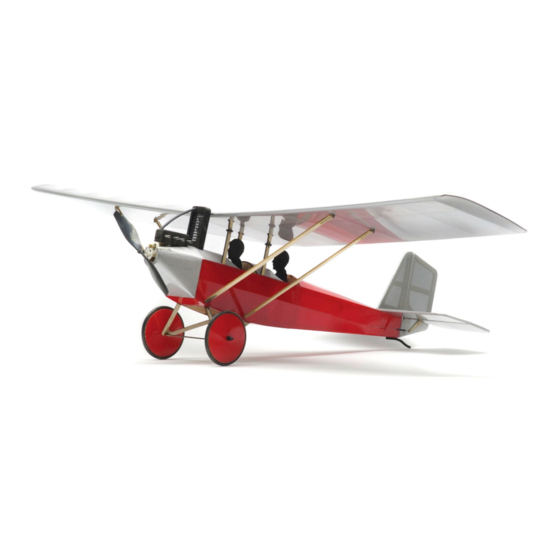
- Page 1 Build Instructions Revised: 06/22/2011 Air Camper (100) By Stevens AeroModel Length 15.25 inches | Span 23.75 inches | Area: 100 inches | Flying Weight 2.1 oz. Version 1.0 © 2011 Stevens AeroModel all rights reserved.! Page 1 of 11...
- Page 2 Revised: 06/22/2011 WARRANTY Stevens AeroModel guarantees this kit to be free from defects in both material and workmanship at the date of purchase. This warranty does not cover any component parts damaged by use or modification. In no case shall Stevens AeroModel’s liability exceed the original cost of the purchased kit. Further, Stevens AeroModel reserves the right to change or modify this warranty without notice.
-
Page 3: Kit Contents
☐ Sanding block with 400 and 600 grit paper ☐ Heat Gun and Covering Iron ☐ Small Needle Nose Pliers ☐ 1/2 in. wide clear tape ☐ Servo mounting tape (optional) ☐ Soldering Iron © 2011 Stevens AeroModel all rights reserved.! Page 3 of 11... - Page 4 (use no glue) the parts together first. It’s advised to work 1-2 steps ahead in the instructions using this dry-fit technique which allows ample opportunity to inspect the fit and location of assembled © 2011 Stevens AeroModel all rights reserved.! Page 4 of 11...
- Page 5 21. Fit two inner stringers F20 to notches closest sides where indicated on plan. Ensure to the center of formers F3, F10, F9, and etching on former faces AFT. F11a. © 2011 Stevens AeroModel all rights reserved.! Page 5 of 11...
- Page 6 - motor mount F28. Lift F30 plans, from parts E1 through E5. Bond with and spread medium CA between the two thin CA.Lightly sand the elevator halves, parts, and re-position. leaving the edges square. © 2011 Stevens AeroModel all rights reserved.! Page 6 of 11...
- Page 7 Note: The bottoms of all ribs should seat flush edges with thin CA. Don’t forget to wick thin with bottom of spars. CA between the spar and the sub-spar W4. © 2011 Stevens AeroModel all rights reserved.! Page 7 of 11...
-
Page 8: Final Assembly
Rudder horn R extends inserting the rear edge of the circuit board in from the RIGHT side of the rudder. Elevator the notch in the rear arm of the receiver tray. © 2011 Stevens AeroModel all rights reserved.! Page 8 of 11... - Page 9 Fit cabane struts to radiator inner frame. Paint radiator parts flat stubs in wing center section. Slide o-rings black. over joint in cabane struts to secure wing to fuselage. © 2011 Stevens AeroModel all rights reserved.! Page 9 of 11...
- Page 10 ☐ Inspect wing for any warps that may have the CG measurement as given above. worked their way in when covering, or while © 2011 Stevens AeroModel all rights reserved.! Page 10 of 11...
- Page 11 You may correspond with check. Stevens AeroModel staff using any of the following methods: ☐ Check for traffic. Proceed to the flight line (With your mentor/instructor if you are a E-Mail - support@stevensaero.com...
Need help?
Do you have a question about the Air Camper 100 and is the answer not in the manual?
Questions and answers