Table of Contents
Advertisement
Quick Links
Build Instructions
April 15, 2014!
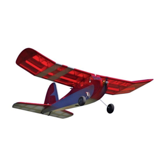
BuzzBomb (400)
A contemporary twist on the free-flight classic Buzzard Bombshell
Wing Span: 40 inches | Wing Area: 355 square inches | Average Flying Weight: 16 ounces
Build Instructions - Version 1.0 (revised 04.15.2014)
(c) 2011 Stevens AeroModel all rights reserved.!
Page 1
Advertisement
Table of Contents

Related Manuals for Stevens AeroModel BuzzBomb 400


Summary of Contents for Stevens AeroModel BuzzBomb 400
- Page 1 A contemporary twist on the free-flight classic Buzzard Bombshell Wing Span: 40 inches | Wing Area: 355 square inches | Average Flying Weight: 16 ounces Build Instructions - Version 1.0 (revised 04.15.2014) (c) 2011 Stevens AeroModel all rights reserved.! Page 1...
- Page 2 April 15, 2014! WARRANTY Stevens AeroModel guarantees this kit to be free from defects in both material and workmanship at the date of purchase. This warranty does not cover any component parts damaged by use or modification. In no case shall Stevens AeroModel’s liability exceed the original cost of the purchased kit. Further, Stevens AeroModel reserves the right to change or modify this warranty without notice.
-
Page 3: Kit Contents
☐ Sanding block with 400 and 600 grit paper ☐ Long sanding bar ☐ Heat Gun and Covering Iron ☐ Masking Tape (Low tack blue painters tape) ☐ Small Needle Nose Pliers (c) 2011 Stevens AeroModel all rights reserved.! Page 3... - Page 4 Build Instructions April 15, 2014! Laser Cut Parts Inventory (c) 2011 Stevens AeroModel all rights reserved.! Page 4...
- Page 5 Build Instructions April 15, 2014! Laser Cut Parts Inventory (c) 2011 Stevens AeroModel all rights reserved.! Page 5...
- Page 6 Build Instructions April 15, 2014! Laser Cut Parts Inventory (c) 2011 Stevens AeroModel all rights reserved.! Page 6...
- Page 7 Please check our web-site for updates to these instructions prior to commencing the build. To obtain downloads and updates relative to this model aircraft kit, please visit the corresponding product page at StevensAero.com (c) 2011 Stevens AeroModel all rights reserved.! Page 7...
- Page 8 Build Instructions April 15, 2014! Builders Notes (c) 2011 Stevens AeroModel all rights reserved.! Page 8...
- Page 9 F4 with thick CA (or aliphatic wood glue) and fit F6 over the tabs protruding through F4. A small amount of each tab will extend through to the other side of F6. Press F6 flush against F4 and hold until the glue cures. (c) 2011 Stevens AeroModel all rights reserved.! Page 9...
- Page 10 Build Instructions April 15, 2014! “top” 90° Step 4 cont. Step 1 Tabs Extend “top” Step 4 cont. Step 2 Step 5 Step 3 Step 6 Step 4 (c) 2011 Stevens AeroModel all rights reserved.! Page 10...
- Page 11 F9 at this time. This will be done at a later step. 14. Fit and bond radio compartment doubler F12 to right fuselage side and ☐ formers F2 and F9. (c) 2011 Stevens AeroModel all rights reserved.! Page 11...
- Page 12 Build Instructions April 15, 2014! F11c F11b F11a Step 11 Step 7 F11e F11d Step 12 Step 8 Step 13 Step 9 Step 14 Step 10 (c) 2011 Stevens AeroModel all rights reserved.! Page 12...
- Page 13 23. Fit the wing saddle F20 to the tops of formers F2, F10, and F9. Tack glue ☐ to former F2 only, leaving the rest of the wing saddle un-glued to allow for adjustment when the fuselage sides are wrapped around former F9. (c) 2011 Stevens AeroModel all rights reserved.! Page 13...
- Page 14 Build Instructions April 15, 2014! Step 15 Step 20 Step 16 Step 21 Step 17 Step 22 Tack Glue Here ONLY Step 19 Step 23 (c) 2011 Stevens AeroModel all rights reserved.! Page 14...
- Page 15 Bond all mating surfaces between bottom, sides, and formers with thin CA. 31. Bond bottom sheeting F24 to fuselage sides immediately behind, and ☐ tabbing into, former F2. (c) 2011 Stevens AeroModel all rights reserved.! Page 15...
-
Page 16: Table Of Contents
Build Instructions April 15, 2014! DO NOT Step 24 Step 28 BOND DOWEL Sand Flush Step 25 Step 29 Step 26 Step 30 Stringer Step 27 Step 31 (c) 2011 Stevens AeroModel all rights reserved.! Page 16... -
Page 17: Step
39. Pass a length of the yellow nylon pushrod housing through the rear exit slot ☐ on the left side of the fuselage, and through the corresponding left hole in former F17. (c) 2011 Stevens AeroModel all rights reserved.! Page 17... -
Page 18: Step
Build Instructions April 15, 2014! F25a Magnet F25b Step 32 Step 36 Step 33 Step 37 Step 34 Step 38 Step 35 Step 39 (c) 2011 Stevens AeroModel all rights reserved.! Page 18... -
Page 19: Step
46. Sand the rear portion of the stringers flush across the top of former F17. ☐ Electronics Hatch 47. Assemble the hatch sheeting from parts H1a, H1b, and H1c. ☐ (c) 2011 Stevens AeroModel all rights reserved.! Page 19... -
Page 20: C) 2011 Stevens Aeromodel All Rights Reserved
Build Instructions April 15, 2014! Step 44 Step 40 Sand Round Carve / Sand Step 45 Step 41 Sand Flush Step 46 Step 42 Sand Step 47 Step 43 (c) 2011 Stevens AeroModel all rights reserved.! Page 20... -
Page 21: Step
55. Follow the procedures in step 53 to build the horizontal stabilizer and ☐ elevator over the plan on Detail Sheet 2. The horizontal stabilizer will be built from parts H1 through H7, and the elevator from parts E1 through E6. (c) 2011 Stevens AeroModel all rights reserved.! Page 21... -
Page 22: Step
Build Instructions April 15, 2014! Magnet Step 52 Step 48 Step 53 Step 49 45° Step 54 Step 50 Step 55 Step 51 (c) 2011 Stevens AeroModel all rights reserved.! Page 22... -
Page 23: Step
63. Fit gusset W6b to the trailing edge W6a and rib W3. Hold wing down ☐ ☐ on a flat surface and bond W6a to the trailing edge and rib W3. (c) 2011 Stevens AeroModel all rights reserved.! Page 23... -
Page 24: Step
Build Instructions April 15, 2014! 45° Step 60 Step 56 Step 61 Step 57 Step 62 Step 58 Right Left Step 63 Step 59 (c) 2011 Stevens AeroModel all rights reserved.! Page 24... - Page 25 70. Repeat step 59 through 69 to build the right half of the wing. ☐ 71. Hold the center section ribs W3 down on a flat surface. Fit and bond center ☐ trailing edge part W15 between ribs W3 and trailing edge parts W6a. (c) 2011 Stevens AeroModel all rights reserved.! Page 25...
-
Page 26: C) 2011 Stevens Aeromodel All Rights Reserved
Build Instructions April 15, 2014! Step 68 Step 64 Step 69 Step 65 Step 70 Step 66 Step 71 Step 67 (c) 2011 Stevens AeroModel all rights reserved.! Page 26... -
Page 27: Step
78. Fit and tack glue the leading edge web W23 to leading edge of ribs W5 and ☐ ☐ W21. 79. Fit and tack glue the leading edge W24 to the leading edge web W23 and ☐ ☐ ribs W5 and W21. (c) 2011 Stevens AeroModel all rights reserved.! Page 27... -
Page 28: Step
Build Instructions April 15, 2014! Step 76 Step 72 Step 77 Step 73 Step 78 Step 74 Step 79 Step 75 (c) 2011 Stevens AeroModel all rights reserved.! Page 28... -
Page 29: Step
86. Trim and sand the rear part of the reinforcement until it flows smoothly into ☐ ☐ the wing tip sheeting. 87. Sand the bottom of the trailing edge until it meets and flows into the bottom ☐ ☐ of the tip sheeting. (c) 2011 Stevens AeroModel all rights reserved.! Page 29... -
Page 30: Step
Build Instructions April 15, 2014! Step 84 Step 80 Step 85 Step 81 W28a W28b W28c Step 82 Step 86 Step 83 Step 87 (c) 2011 Stevens AeroModel all rights reserved.! Page 30... -
Page 31: Step
W25, and the wing tip sheeting W28. Spar W35 will lie closest to the main tip spar, and W36 will lie closest to the leading edge. Now bond all turbulator spars installed in steps 92 - 95 within wing assembly. (c) 2011 Stevens AeroModel all rights reserved.! Page 31... - Page 32 Build Instructions April 15, 2014! Step 92 Step 88 W29b W29a Step 93 Step 90 Step 94 Step 91 Step 95 Step 91 cont. (c) 2011 Stevens AeroModel all rights reserved.! Page 32...
-
Page 33: Final Assembly
Set the wing aside until Final Assembly. Final Assembly 98. Cover the model with a lightweight material such as Stevens AeroModel ☐ AeroITE or AeroFILM. 99. With a warm soldering iron, open the covering over the holes for the wing ☐... - Page 34 Build Instructions April 15, 2014! Step 99 cont. Step 96 Step 100 Step 97 Step 101 Step 98 Step 101 cont. Step 99 (c) 2011 Stevens AeroModel all rights reserved.! Page 34...
- Page 35 Correct this if necessary, relocating the washers under the left mounting tabs. 109. Pull the wiring through one of the holes running along each side of F1, into ☐ the radio compartment. (c) 2011 Stevens AeroModel all rights reserved.! Page 35...
-
Page 36: Step
Build Instructions April 15, 2014! Nylon Washers Step 102 Step 106 Step 103 Step 107 WSD1300 Step 104 Step 108 SUP30AESC Step 105 SUPA2212-6 Step 109 (c) 2011 Stevens AeroModel all rights reserved.! Page 36... - Page 37 118. Retain the wheel and bushing with one of the rubber wheel retainers. ☐ ☐ 119. Repeat steps 117 and 118 to mount the remaining bushing and wheel. ☐ (c) 2011 Stevens AeroModel all rights reserved.! Page 37...
- Page 38 Build Instructions April 15, 2014! Step 110 Step 115 Cut two 5/8 in. Lengths Step 111 Step 116 Bushing Step 112 Step 117 Rubber Retainer Step 114 Step 118 (c) 2011 Stevens AeroModel all rights reserved.! Page 38...
- Page 39 The elevator horn extends from the lower left side of the elevator. 127. Fit the retention plates over the posts of the control horns, and press them ☐ down firmly against the control surface. (c) 2011 Stevens AeroModel all rights reserved.! Page 39...
-
Page 40: Step
Build Instructions April 15, 2014! Step 120 Step 124 #32 Rubber Band Step 121 Step 125 DUB853 DUB936 Step 122 Step 126 Step 123 Step 127 (c) 2011 Stevens AeroModel all rights reserved.! Page 40... -
Page 41: Step
Now, center the control surfaces, and tighten down the E/Z Connectors to secure the pushrods. Trim the pushrods about 1/2 in. beyond the servo control arms. (c) 2011 Stevens AeroModel all rights reserved.! Page 41... -
Page 42: Step
Build Instructions April 15, 2014! Step 128 Step 132 Step 129 Step 133 Step 134 Safety DUB849 Step 130 Step 135 Step 131 Trim (c) 2011 Stevens AeroModel all rights reserved.! Page 42... -
Page 43: Step
We hope you enjoyed building your BUZZ 400™. Proceed to the Setup and Pre-Flight sections of this manual to prepare your BUZZ 400™ for flight. (c) 2011 Stevens AeroModel all rights reserved.! Page 43... -
Page 44: Step
Build Instructions April 15, 2014! Step 136 Step 140 Step 137 Step 141 Step 138 Step 139 (c) 2011 Stevens AeroModel all rights reserved.! Page 44... -
Page 45: Step
☐ Inspect battery for full charge. Never begin a flight with a partially charged battery. ☐ Clear prop! Before applying power to the model, clear and keep clear of the prop arc. (c) 2011 Stevens AeroModel all rights reserved.! Page 45... -
Page 46: Step
You may correspond with ☐ Check for traffic. Proceed to the flight line Stevens AeroModel staff using any of the (With your mentor/instructor if you are a following methods: novice pilot) and observe other RC traffic.
Need help?
Do you have a question about the BuzzBomb 400 and is the answer not in the manual?
Questions and answers