
Related Manuals for Stevens AeroModel Stinson 105 UM


Summary of Contents for Stevens AeroModel Stinson 105 UM
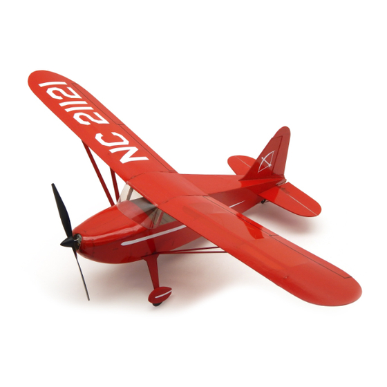
- Page 1 Wing Span: 21.25 inches | Wing Area: 64 square inches | Average Flying Weight: 1.75 ounces Build Instructions - Version 1.12 (revised 10.15.2015)
- Page 2 Build Instructions WARRANTY Stevens AeroModel guarantees this kit to be free from defects in both material and workmanship at the date of purchase. This warranty does not cover any component parts damaged by use or modification. In no case shall Stevens AeroModel’s liability exceed the original cost of the purchased kit. Further, Stevens AeroModel reserves the right to change or modify this warranty without notice.
- Page 3 The Stevens AeroModel Stinson 105 UM features a modern kit design that builds trouble-free and quickly, thanks to modern design processes pioneered by Stevens AeroModel. Stinson 105 UM - Build Instructions © 2015 Stevens AeroModel, all rights reserved.! Page 3...
- Page 4 Many of the suggested items listed below are available at your local hobby shop. For your convenience, Stevens AeroModel stocks all the power system components and most of the building supplies required to complete this kit. If you have difficulties sourcing any of these items locally, please visit our website, stevensaero.com to purchase the items necessary to complete your model.
- Page 5 Build Instructions Sheet Wood Inventory (1 of 1) Stinson 105 UM - Build Instructions © 2015 Stevens AeroModel, all rights reserved.! Page 5...
- Page 6 Build Instructions Builder’s Notes Stinson 105 UM - Build Instructions © 2015 Stevens AeroModel, all rights reserved.! Page 6...
- Page 7 Please check our website for updates to these instructions before starting the build. To obtain downloads and updates for this model aircraft kit, please visit the product page at stevensaero.com Stinson 105 UM - Build Instructions © 2015 Stevens AeroModel, all rights reserved.! Page 7...
- Page 8 Turn F7 right side up, so that the receiver tray is underneath. Fit and “tack glue” F7 to the back of F5. □ Assemble former F8 from parts F8a, F8c, and two parts F8b, (sheet 10/10, 1/32 in. ply). Bond with CA. Stinson 105 UM - Build Instructions © 2015 Stevens AeroModel, all rights reserved.! Page 8...
- Page 9 Bottom Bottom View Step 3 Step 7 Tabs Top View F7 - Top Receiver Tray Underneath Top View Step 4 Step 8 Tabs Rear View Stinson 105 UM - Build Instructions © 2015 Stevens AeroModel, all rights reserved.! Page 9...
- Page 10 □ Fuselage Rear – Fit and “tack glue” former F12 (sheet 03/10, 1/20 in. balsa) into the slots in the fuselages sides behind former F9. Stinson 105 UM - Build Instructions © 2015 Stevens AeroModel, all rights reserved.! Page 10...
- Page 11 Step 9 Step 13 Bond from the Inside Step 10 Step 13 Cont. F10a Step 11 Step 14 Step 12 Step 15 F10d F10b F10c F10a Stinson 105 UM - Build Instructions © 2015 Stevens AeroModel, all rights reserved.! Page 11...
- Page 12 Do not bond at this time. □ Fit F17 (sheet 10/10, 1/32 in. ply) immediately behind and flush against F16. Do not bond. Stinson 105 UM - Build Instructions © 2015 Stevens AeroModel, all rights reserved.! Page 12...
-
Page 13: Step
Step 16 Step 20 Step 17 Step 20 Cont. F14a Step 18 Step 21 F14b Bottom View Step 19 Step 22 F15b F15a Bottom View Stinson 105 UM - Build Instructions © 2015 Stevens AeroModel, all rights reserved.! Page 13... - Page 14 F9. Fit and bond F22 (sheet 05/10, 1/20 in. balsa) to the notches at the front of parts F20, and into the notch in the center of F18. Stinson 105 UM - Build Instructions © 2015 Stevens AeroModel, all rights reserved.! Page 14...
- Page 15 Step 26 F19a F19b Bottom View F19c F19d Step 25 Step 26 Cont. Bottom View Bottom View Step 25 Cont. Step 27 Bottom View Bottom View Stinson 105 UM - Build Instructions © 2015 Stevens AeroModel, all rights reserved.! Page 15...
- Page 16 Slide F29 (sheet 08/10, 1/8 in. balsa) over the same tabs until it is flush against F28. Bond □ with CA. □ Slide F30 (sheet 08/10, 1/8 in. balsa) over the tabs on parts F2 until flush against F29. Bond with CA. Stinson 105 UM - Build Instructions © 2015 Stevens AeroModel, all rights reserved.! Page 16...
- Page 17 Bottom View Bottom View Step 29 Step 33 Bottom View Tabs Tabs Step 30 Step 34 Bottom View Tabs Step 31 Step 35 Bottom View Stinson 105 UM - Build Instructions © 2015 Stevens AeroModel, all rights reserved.! Page 17...
- Page 18 Bond with CA. □ Position parts F37 (sheet 09/10, 3/16 in. balsa) over both F36s. Position both F37s flush. against the edges of F33. Bond with CA. Stinson 105 UM - Build Instructions © 2015 Stevens AeroModel, all rights reserved.! Page 18...
-
Page 19: Step
Build Instructions Step 36 Step 40 Step 37 Step 41 Step 38 Step 42 F33a F33b Step 39 Step 43 Stinson 105 UM - Build Instructions © 2015 Stevens AeroModel, all rights reserved.! Page 19... - Page 20 Use a sanding stick or sanding block to sand a 45-degree bevel along the entire leading edge. The bevelled side of the elevator will now be referred to as the bottom. Stinson 105 UM - Build Instructions © 2015 Stevens AeroModel, all rights reserved.! Page 20...
- Page 21 45 deg. Left Etched Line Top View Step 46 Step 50 Etched Line Bottom View Step 47 Step 51 Bottom View Bottom 45 deg. End View Stinson 105 UM - Build Instructions © 2015 Stevens AeroModel, all rights reserved.! Page 21...
-
Page 22: Final Assembly
AeroLite, available at stevensaero.com. Cover the fuselage. Leave the bottom aft of the landing gear pocket uncovered until after the radio and pushrods have been installed. Stinson 105 UM - Build Instructions © 2015 Stevens AeroModel, all rights reserved.! Page 22... - Page 23 Step 52 Step 56 Step 53 Step 57 Tack Glue Bottom View Step 54 Step 58 Step 55 Step 58 Cont. Etched Side UP! Bottom View Stinson 105 UM - Build Instructions © 2015 Stevens AeroModel, all rights reserved.! Page 23...
- Page 24 Cover the bottom of the fuselage. Use a sharp hobby knife to remove the covering over the □ opening for the radio compartment. Stinson 105 UM - Build Instructions © 2015 Stevens AeroModel, all rights reserved.! Page 24...
- Page 25 Step 61 Step 63 Cont. .015 Wire Pushrods Exit Slot on Left Side Step 62 Step 63 Cont. Center Hole Exit Slot on Right Side Stinson 105 UM - Build Instructions © 2015 Stevens AeroModel, all rights reserved.! Page 25...
-
Page 26: Landing Gear
LG1 (sheet 10/10, 1/32 in. balsa) into the pocket until it is flush with the bottom of the fuselage. Wick CA along the pocket and at the point where the landing gear wire exits, to secure it in place. Stinson 105 UM - Build Instructions © 2015 Stevens AeroModel, all rights reserved.! Page 26... - Page 27 Bottom View Spikes Step 65 Cont. Step 68 Hump Top View Step 66 Step 69 1/32 in. Wire Step 66 Cont. Step 70 Bottom View Stinson 105 UM - Build Instructions © 2015 Stevens AeroModel, all rights reserved.! Page 27...
- Page 28 Flex the elevator back and forth, making sure that it moves freely with no binding. If it does not move freely, remove the tape hinge and repeat the hinging process, slightly increasing the gap between the surfaces. Stinson 105 UM - Build Instructions © 2015 Stevens AeroModel, all rights reserved.! Page 28...
- Page 29 Step 74 Bottom View Step 71 Cont. Step 75 Trim Bottom View Step 72 Step 76 Bottom View No Glue! Medium CA Bevelled Side Down! Stinson 105 UM - Build Instructions © 2015 Stevens AeroModel, all rights reserved.! Page 29...
-
Page 30: Control Linkages
The Pushrod Detail drawing on Detail Sheet 2 of 2. Trim the connectors to an overall length of 5/8 in. Save the scraps for the next step. Stinson 105 UM - Build Instructions © 2015 Stevens AeroModel, all rights reserved.! Page 30... - Page 31 Right Side Step 79 Step 83 Bottom View Bevelled Side Up 1/8 in. Left Bottom View Step 80 Step 84 5/8 in. Remove .015 in. Wire Stinson 105 UM - Build Instructions © 2015 Stevens AeroModel, all rights reserved.! Page 31...
- Page 32 “final bond” the wing struts with medium CA. Apply a small bead of medium CA along the top of the strut base where it meets the fuselage side. Stinson 105 UM - Build Instructions © 2015 Stevens AeroModel, all rights reserved.! Page 32...
- Page 33 Step 89 3/8 in. Bond Bond Bottom View Step 86 Step 90 Bond Bottom View Bottom View Step 87 Step 90 Cont. Notch Medium CA Stinson 105 UM - Build Instructions © 2015 Stevens AeroModel, all rights reserved.! Page 33...
- Page 34 Congratulations! The Stinson 105 UM is now complete. Please continue to the Setup and Preflight sections of these build instructions to prepare your model for flight. Stinson 105 UM - Build Instructions © 2015 Stevens AeroModel, all rights reserved.!
- Page 35 Moving the elevator stick forward should move the elevator down. The Stinson 105 UM was designed to be a very docile flyer. We set up our flight controls with fairly minimal throws. With the push rods connected, per the instructions in this manual, set the control throws...
- Page 36 Fly the model to a comfortable “1 to 2 mistakes high altitude”, reduce throttle to stop the climb, then trim the model for straight-and-level flight at a comfortable cruise speed. The Stinson 105 UM typically cruises at just over one-half throttle.
Need help?
Do you have a question about the Stinson 105 UM and is the answer not in the manual?
Questions and answers