Advertisement
Quick Links
Quick Start Guide
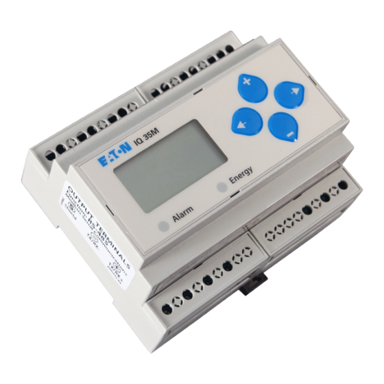
IQ 35M Meter Series
DANGER
HAZARD OF ELECTRIC SHOCK, EXPLOSION, OR ARC FLASH
• Follow safe electrical work practices. See NFPA 70E in the USA, or applicable local codes.
• This equipment must only be installed and serviced by qualified electrical personnel.
• Read, understand and follow the instructions before installing this product.
• Turn off all power supplying equipment before working on or inside the equipment.
• Any covers that may be displaced during the installation must be reinstalled
before powering the unit.
• Use a properly rated voltage sensing device to confirm power is off.
DO NOT DEPEND ON THIS PRODUCT FOR VOLTAGE INDICATION
Failure to follow these instructions will result in death or serious injury.
NOTICE
• This product is not intended for life or safety applications.
• Do not install this product in hazardous or classified locations.
• The installer is responsible for conformance to all applicable codes.
• Mount this product inside a suitable fire and electrical enclosure.
FCC PART 15 INFORMATION
NOTE: This equipment has been tested by the manufacturer and found
to comply with the limits for a class B digital device, pursuant to part
15 of the FCC Rules. These limits are designed to provide reasonable
protection against harmful interference when the equipment is
operated in a residential environment. This equipment generates, uses,
and can radiate radio frequency energy and, if not installed and used
in accordance with the instruction manual, may cause harmful
interference to radio communications. Operation of this equipment in
a residential area may cause harmful interference in which case the
user will be required to correct the interference at his own expense.
Modi cations to this product without the express authorization of the
manufacturer nullify this statement.
CAUTION
RISK OF EQUIPMENT DAMAGE
• This product is designed only for use with 1V or 0.33V current
transducers (CTs).
• DO NOT USE CURRENT OUTPUT (e.g. 5A) CTs ON THIS PRODUCT.
• Failure to follow these instructions can result in overheating and
permanent equipment damage.
1
IQ 35M Meter Series IB02601008E September 2011 www.eaton.com
Specifications
Measurement Accuracy:
Real Power and Energy
Input Voltage Characteristics:
Measured AC Voltage
Impedance
Frequency Range
Input Current Characteristics:
Measurement Input Range
Impedance
Control Power:
AC
DC *
Ride Through Time
Mechanical Characteristics:
IP Degree of Protection (IEC 60529)
Terminal Block Screw Torque
Terminal Block Wire Size
Rail
Environmental Conditions:
Operating Temperature
Storage Temperature
Humidity Range
Altitude of Operation
Metering Category:
North America
CE
Dielectric Withstand
Conducted and Radiated Emissions
Conducted and Radiated Immunity
Safety:
North America (cULus)
Europe (CE)
* External DC current limiting is required. See Fuse Recommendations
For use in a Pollution Degree 2 or better environment only. A Pollution Degree 2
environment must control conductive pollution and the possibility of condensation
or high humidity. Consider the enclosure, the correct use of ventilation, thermal
properties of the equipment, and the relationship with the environment. Installation
category: CAT II or CAT III
Provide a disconnect device to disconnect the meter from the supply source. Place
this device in close proximity to the equipment and within easy reach of the opera-
tor, and mark it as the disconnecting device. The disconnecting device shall meet
the relevant requirements of IEC 60947-1 and IEC 60947-3 and shall be suitable
for the application. In the US and Canada, disconnecting fuse holders can be used.
Provide overcurrent protection and disconecting device for supply conductors with
approved current limiting devices suitable for protecting the wiring. If the equipment
is used in a manner not specified by the manufacturer, the protection provided by
the device may be impaired.
This symbol indicates an electrical
shock hazard exists.
Documentation must be consulted where
this symbol is used on the product.
Additional Resources:
For a copy of the full installation guide
for this product, visit www.eaton.com
IEC 62053-22 Class 0.5S, ANSI C12.20
0.5%
Min. 90 V
(156 V
) for stated accuracy
L -N
L-L
UL Maximums: 600 V
(347 V
)
L-L
L-N
CE Maximums: 300 V
(520 V
)
L-N
L-L
2.5 MΩ (L-N)/5 MΩ (L-L)
45 to 65 Hz
0 to 0.333 VAC or 0 to 1.0 VAC
(+20% over-range)
10.6 kΩ (1/3 V mode) or 32.1 kΩ (1 V mode)
5 VA max.; 90 V min.
UL Maximums: 600 V
(347 V
)
L-L
L-N
CE Maximums: 300 V
(520 V
)
L-N
L-L
3 W max.; UL and CE: 125 to 300 VDC
100 msec at 120VAC
IP40 front display; IP20 Meter
3.5 in-lb (0.4 N·m) nominal/
4.4 in-lb (0.5 N·m) max.
14 to 24 AWG
T35 (35mm) DIN Rail per EN50022
-30° to 70°C
-40° to 85°C
<95% RH (non-condensing)
3 km max.
CAT III; for distribution systems
up to 347 V
/600 VAC
L-N
L -L
CAT III; for distribution systems
up to 300 V
L -N
Per UL 508, EN61010
FCC part 15 Class B, EN55011/EN61000
Class B (residential and light industrial)
EN61000 Class A (heavy industrial)
UL508 (open type device)/
CSA 22.2 No. 14-05
EN61010-1:2001
ZL0073-0C
RoHS
Compliant
Advertisement

Related Manuals for Eaton IQ 35M Series


Summary of Contents for Eaton IQ 35M Series
- Page 1 Documentation must be consulted where this symbol is used on the product. Additional Resources: For a copy of the full installation guide RoHS for this product, visit www.eaton.com Compliant IQ 35M Meter Series IB02601008E September 2011 www.eaton.com ZL0073-0C...
-
Page 2: Dimensional Drawings
(all except IQ 35MA15), the UL: 90V - 600V CE: 90V - 300V two Eaton IQ35M-DRSC end stop clips or equivalent. CAT III 50/60 Hz 0.1A 50/60 Hz green Energy LED lights when the Energy pulse output contacts are closed. -
Page 3: Display Diagram
Current Transducer Potential Transformer Protection containing a voltage disconnect switch with a fuse or disconnect circuit breaker. The protection device must be rated for the available short-circuit current at the connection point. IQ 35M Meter Series IB02601008E September 2011 www.eaton.com ZL0073-0C... -
Page 4: Wiring Diagrams
Output to meet meter input requirements When tightening terminals, ensure that the correct DC Control Powerfrom 125VDC to 300VDC (UL and CE max.). torque is applied: 3.5 - 4.4 in·lb (0.4-0.5 N·m). IQ 35M Meter Series IB02601008E September 2011 www.eaton.com ZL0073-0C... - Page 5 Use with contacts that do not require current to remove oxidation. Pulse Input Contacts – ~10 k Equivalent Circuit Comm 4-10 VDC nominal Ground IQ 35M Meter Series IB02601008E September 2011 www.eaton.com ZL0073-0C...
-
Page 6: Quick Setup Instructions
– to select the ID digits (default is a pseudo-random number). the full setup instructions, see the full installation guide for the specific model at www.eaton.com. 5. Press to accept the value and go to the ID2 screen and through the lower three digits of the –...