
Related Manuals for Eaton KK650


Summary of Contents for Eaton KK650
- Page 1 Instruction manual January 2017 MTL gas analysers & systems INM MTL 130-0202 Rev 4 KK650 MTL hydrogen and chlorine gas analyser...
- Page 2 DECLARATION OF CONFORMITY A printed version of the Declaration of Conformity has been provided separately within the original shipment of goods. However, you can find a copy of the latest version at - http://www.mtl-inst.com/certificates INM MTL 130-0202 Rev 4...
-
Page 3: Table Of Contents
CONTENTS DECLARATION OF CONFORMITY ............ii INTRODUCTION . - Page 4 THIS PAGE IS LEFT INTENTIONALLY BLANK INM MTL 130-0202 Rev 4...
-
Page 5: Introduction
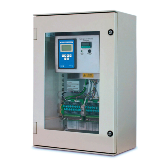
INTRODUCTION The KK650 measures hydrogen in the ranges 0 to 5% or 0 to 10% (depending on the model), and also chlorine in the range 0 to 100%, when these gases are mixed with air. It is designed specifically for the chlor-alkali industry. Chlorine is usually manufactured by the electrolysis of brine (sodium chloride) or potassium chloride. -
Page 6: Manual Symbols
Manual symbols The following methods are used in this manual to alert the user to important information:- WARNING Warnings are provided to ensure operator safety and MUST be followed. CAUTION A Caution is provided to prevent damage to the instrument. NOTE These are used to give general information to ensure correct operation... -
Page 7: Specification
SPECIFICATION Two instrument range options are available. See below. Ranges Ranges Gas mix Display resolution Range 1 in Cl and background gas 0.01% 0…5% max. Option 1 Range 2 0…100% in H and background gas 0.1% Range 1 0…10% max. in Cl and background gas 0.01%... -
Page 8: Analogue Outputs
2.11 Analogue outputs 4 to 20mA – programmable as follows: Range Gas measured Low End High End 20mA equiv. to 1.00%…5.00% Range 1 4mA equiv. to 0% Option 1 - user adjustable Range 2 4mA equiv. to 0% 20mA equiv. to 100% - fixed 20mA equiv. -
Page 9: Installation
INSTALLATION WARNING The weight of this equipment is in excess of 18kg, and the use of mechanical handling equipment or assistance from additional personnel is recommended when handling and mounting. Unpacking and visual checking Take all standard precautions when opening packages. In particular avoid the use of long bladed cutters. - Page 10 NOTE Care must be taken to ensure that the tubing etc, carrying the sample from the take-off point to the katharometer entry is completely obscured from any light, otherwise the analyser will report a lower hydrogen concentration for the sampled process gas. This fact would of course be true for any other thermal conductivity analyser performing this measurement.
-
Page 11: Katharometer/Reactor Assembly
Katharometer/reactor assembly This is shown below. It must be mounted upright as shown, in an ambient that is between 5°C and 55°C and not subjected to excessive vibration. 240mm Four mounting holes on Side view 220mm x 130mm centres, Katharometer Assembly suitable for M6 (¼”) screws WARNING These parts run HOT... - Page 12 5°C and 45°C and where it will not be subjected to excessive vibration or direct sunlight, with subsequent heating. Hydrogen in Chlorine Analyser Hydrogen in Chlorine Analyser KK650 MTL Hydrogen in Chlorine Analyser Securing nuts (x4) Reactor Temperature...
- Page 13 All low voltage connections are itemised on the white label below the connector terminals, see Figure 6 for details. Figure 6 The cables from the katharometer/reactor unit are identified by number tags that correspond to the terminal numbers on the label. The two heavier wires (labelled 9 and 10) in the black cable from the katharometer should be connected to the DIN-rail mounted terminals between the two carriers.
-
Page 14: Operation
OPERATION First checks It is advisable to make a thorough check of all connections – particularly the pipe work – before applying any sample. WARNING Chlorine is a highly toxic and corrosive gas and it is of utmost importance that there are no leaks. - Page 15 View mode configuration screens View Mode Configuration Screens Hydrogen in Chlorine Analyser KK650 MTL Hydrogen in Chlorine Analyser Hydrogen in Chlorine Analyser Press the VIEW key See next section for to access screen 1 View Edit information on the use...
- Page 16 4.3.2 Edit mode To edit a value, start by pressing the View button to enter the screen choice level. Use the arrow buttons to step through each screen and its options. At the chosen parameter, press the Edit button at which point the following screen is displayed. This is to warn that all outputs will be stopped at their current value if the user goes further.
-
Page 17: Calibration
CALIBRATION General notes Provided the katharometer does not become contaminated, instruments can be expected to hold their calibration repeatability to better than 0.02% hydrogen for a lengthy period. Chlorine accuracy varies according to air and hydrogen concentrations. In the 90 to 100% range it is approximately 0.5% going out to about 1.5% at lower concentrations with high hydrogen. -
Page 18: Calibration Mode
100% of span Chlorine 33/35% of span Argon Thermal Conductivity Calibration mode Hydrogen in Chlorine Analyser Hydrogen in Chlorine Analyser KK650 MTL Hydrogen in Chlorine Analyser Press Cal key for Calibration mode This screen Surrogate appoximately Nonsurrogate appears when VIEW to exit... - Page 19 Calibration screen map INM MTL 130-0202 Rev 4...
-
Page 20: Service And Maintenance
SERVICE AND MAINTENANCE General In keeping with all of our products, the KK650 is a highly reliable analyser. If a fault is apparent on a new installation, the wiring, etc., should be checked thoroughly. Similarly, if the instrument appears not to power up, ensure that a proper supply is in place and that the two fuses are intact. - Page 21 NOTE The codes are additive. E.g. if a code of 5 was displayed it would mean that Vo1 AD counts were less than (-)4093 and Vo2 AD counts were less than (-)4093. Vt is the internal voltage signal that indicates the katharometer’s temperature Vo1 is the internal voltage signal that is a function of the difference between the two katharometer sense signals at terminals 1-2 and 3-4 in Figure 6.
-
Page 22: Trouble-Shooting Chart
Instrument appears to be - see Figure 5. correct. If fuse blows “dead”. again see next symptom. 3. Internal connection 3. Disassemble and 3. Replace KK650 failure. check all connections. electronics – see section 7.9 1. Wrong supply 1. Check actual voltage 1. -
Page 23: Checking The Katharometer
continued SYMPTOM POSSIBLE CAUSE TEST ACTION Fault code 262144. 1. Reactor temperature 1. Examine display of 1. Replace controller outside spec. temperature controller and re-tune if for fault status – As per necessary - contact section 7.8 your local MTL Gas sales office for instructions. -
Page 24: Removal Of Katharometer And Reaction Tube
Removal of katharometer and reaction tube Refer to fig 7 below Sample out Katharometer Assembly Reactor Furnace Sample in M4 stud mounts 4 x ¼” double ferrule Quartz reaction tube Outline of heat shield couplings with 5/8" (16mm) AF nuts Figure 7 1. -
Page 25: Cleaning The Katharometer And Reaction Tube
Cleaning the katharometer and reaction tube The reaction tube may be immersed in water and gently agitated. Any deposit that is not removed may be left in place. Rinse with distilled or de-ionised water and dry it by standing or heating it in an oven (e.g. 55°C for 12 hours). 2. -
Page 26: Re-Mounting The Katharometer And Reaction Tube
Re-mounting the katharometer and reaction tube Re-mounting is the reversal of removal. Always make sure that all ferrules are undamaged and put in place correctly – Figure 3 illustrates this. Re-make all the electrical connections and then apply power to the analyser. Check that the voltages on the elements are correct –... -
Page 27: Restoring Factory Defaults
6.9.2 Removal and replacement The power supply to the instrument must be completely disconnected. The stainless steel electronics unit mounts to the backplate of the enclosure on four captive studs, two each side, and is secured to each with a nut, a locking washer and a plain washer - see Figure 4 (page 8) for details. - Page 28 MTL Instruments GmbH, Heinrich-Hertz-Str. 12, 50170 Kerpen, Germany UNITED ARAB EMIRATES Cooper Industries/Eaton Corporation Tel: +49 (0)22 73 98 12 - 0 Fax: +49 (0)22 73 98 12 - 2 00 Office 205/206, 2nd Floor SJ Towers, off. Old Airport Road, E-mail: csckerpen@eaton.com...
Need help?
Do you have a question about the KK650 and is the answer not in the manual?
Questions and answers