Table of Contents
Advertisement
Advertisement
Table of Contents

Subscribe to Our Youtube Channel
Related Manuals for Pixsys ATR144


Summary of Contents for Pixsys ATR144
- Page 1 ATR144 Controller / Regolatore User manual / Manuale d’uso...
-
Page 3: Table Of Contents
Table of contents 1 Introduction ......................6 2 Safety guidelines ....................6 Environmental policy / WEEE ..............7 3 Model identification ....................7 4 Technical data ......................7 General features ..................7 Hardware features ..................8 Software features ..................9 Programming mode .................. - Page 4 13 Alarm Intervention Modes................80 13.1 Alarms label ....................84 14 Table of anomaly signals ...................85 Indice degli argomenti 1 Introduzione ......................92 2 Norme di sicurezza ....................92 Tutela ambientale e smaltimento dei rifiuti / Direttiva WEEE 93 3 Identificazione di modello................93 4 Dati tecnici ......................93 Caratteristiche generali ................93 Caratteristiche Hardware...............94 Caratteristiche software.................95...
- Page 5 11 Accesso alla configurazione ................130 11.1 Caricamento valori di default ............131 11.2 Funzionamento della lista parametri ..........132 12 Tabella parametri di configurazione ............132 13 Modi d’intervento allarme ................168 13.1 Label allarmi ..................... 172 14 Tabella segnalazioni anomalie..............173 Index des sujets 1 Introduction ......................
-
Page 6: Introduction
Introduction PID Controller ATR144 relies on Pixsys flagship programming mode by NFC/RFID technology with dedicated App MyPixsys for Android devices (same already used for Pixsys signal converters and STR indicators) not requiring wirings and power supply, allowing quick set-up/updates on site. -
Page 7: Environmental Policy / Weee
Power supply 24..230 VAC/VDC ±15% 50/60 Hz – 5 Watt/VA ATR144-ABC 1 analogue input + 2 relays 5 A + 1 D.I/O ATR144-ABC-T 1 analogue input + 1 relays 5 A + 1 D.I/O + RS485 Technical data General features 4 digits 9.6 mm (0.38 pollici), 5 digits 7.1... -
Page 8: Hardware Features
5 A - 250 VAC outputs and alarm output. Resistive load. Configurable as command 12 V, 25 mA. outputs and alarm output. Extended power-supply Power- Consumption: 5 24..230 VAC/VDC ±15% supply Watt/VA 50/60 Hz 8 - ATR144 - User manual... -
Page 9: Software Features
Programming mode by keyboard ..see paragraph software ..on “Download section” of official pixsys LabSoftview site: www.pixsys.net ..through download the App on Google Play Store®, see paragraph When activated by a reader/ App MyPixsys... -
Page 10: Dimensions And Installation
• Avoid proximity of power groups, especially those with phase control. • It is strongly recommended to install adequate mains fi lter on power supply of the machine where the controller is 10 - ATR144 - User manual... -
Page 11: Wiring Diagram
1/8HP source 1/8HP source DI/O1 DI/O1 24...230V 24...230V (NPN) (NPN) AC/DC AC/DC RS485 6.1.a Power supply Switching power supply 24..230 VAC/ Class 2 source VDC ±15% 50/60 Hz - 5 Watt/VA. 24...230 VAC/DC Galvanic insulation. User manual - ATR144- 11... - Page 12 For linear signals in Volt and mA Shield/Schermo • Comply with polarity • When shielded cable is used, it should be grounded at one side only to avoid ground loop currents. 12 - ATR144 - User manual...
- Page 13 P and N. For signals 0/4..20mA with two-wire sensor • Comply with polarity C = Sensor output A = Sensor power supply (12V/30mA) 0/4...20mA In the picture: pressure sensor. User manual - ATR144- 13...
- Page 14 RTU Slave with galvanic insulation. It is recommended to use the twisted Shield/Schermo and shielded cable for communications. 6.1.g Digital output Digital output NPN (including SSR) for DI/O1 (NPN) command or alarm. Range 12 VDC/25 mA. 14 - ATR144 - User manual...
- Page 15 Capacity 5 A / 250 VAC for resistive 5A 230V loads. Resistive 1/8HP See chart below. 6.1.i Relay output Q2 (only on ATR144-ABC) Capacity 5 A / 250 VAC for resistive 5A 230V Resistive loads. 1/8HP See chart below. Contact Q1 e Q2: •...
-
Page 16: Display And Key Functions
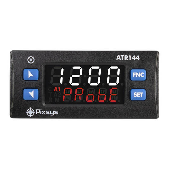
Normally displays the process. During the configuration phase, it displays the 123. 4 parameter groups or the parameter being inserted. Normally displays the setpoint. During the configuration phase, it displays the PRobe parameter value being inserted. 16 - ATR144 - User manual... -
Page 17: Meaning Of Status Lights (Led)
• Allows to visualize command and alarm setpoints. • During configuration allows to enter the parameter to be modified and confirms the variation. • Allows to enter the Tuning launch function, automatic/manual selection. • During configuration works as exit key (ESCAPE). User manual - ATR144- 17... -
Page 18: Controller Functions
PID parameters. Led T flashes. If the PID parameters are not yet selected, at the device switch-on, the manual tunig procedure described in the next paragraph will be launched described into the next paragraph. 18 - ATR144 - User manual... -
Page 19: Manual Tune
Tuning performed once Set once on parameter 36 tun. 1 , or on parameter 98 tun.2. Autotuning procedure is executed only once at next ATR144 restart. If the procedure doesn’t work, it will be be executed at next restart. -
Page 20: Synchronized Tuning
0 the value of word 1210: the various devices will regulate the temperature independently, with the new calculated values. N.B. The master must read the word 1210 at least every 10 seconds or the controller will automatically exit the autotuning procedure. 20 - ATR144 - User manual... -
Page 21: Digital Input Functions
Digital input functions The ATR144 functions related to digital inputs can be enabled by parameters 94 d. i . 1 .F. and 101 d. i .2.F.. • 2t.Sw.: Two threshold setpoint modification: with digital input active the ATR144 regulates on SET2, otherwise it regulates on SET1;... - Page 22 • up.key: simulates the operation of the up button. • down.k.: simulates the operation of the down button. • fnc .k.: simulates the operation of the button. • set .k.: simulates the operation of the button. 22 - ATR144 - User manual...
-
Page 23: Automatic / Manual Regulation For % Output Control
PID immediately before breakage. Ex: on an extruder the command in percentage of the resistance (load) is maintained also in case of input sensor failure. User manual - ATR144- 23... -
Page 24: Loop Break
During activation of the actuator, the process is supposed to change towards the setpoint. If this change is not consistent or fast enough, atr144 will display the message”loop break alarm”. This message won’t be shown if parameter 62 or 78 are set to “L.B.A” - in this case the regulator generates an alarm, enables the corresponding output and displays the message selected in the parameter 72 (“alarm 1... -
Page 25: Dual Action (Heating-Cooling)
Dual Action (Heating-Cooling) ATR144 is suitable also for systems requiring a combined heating-cooling action. The command output has to be configured as PID for Heating (Par. 19 ac.t. 1 = Heat and P.b. 1 greater than 0), and one of the alarms (AL. - Page 26 Parameter c.c.T. 1 has the same meaning of cycle time for heating action c.t. 1. Parameter co.f. 1 (Cooling Fluid) pre-selects the proportional band multiplier p.b.m. 1 and the cooling PID cycle time c.c.T. 1 according to cooling fluid type: 26 - ATR144 - User manual...
- Page 27 Cooling fluid co.f. 1 p.b.m. 1 c.c.t. 1 type 1.00 1.25 Water 2.50 Once parameter co.f. 1 has been selected, the parameters p.b.m. 1 , o.d.b. 1 and c.c.T. 1 can be however modified. User manual - ATR144- 27...
-
Page 28: Funzione Latch On
Display shows HiGh. place the sensor to zero point. Set virtual zero. Display shows zero. If “Virtual zero at To exit procedure press SET. start”is selected, point 4 must be repeated at each starting. 28 - ATR144 - User manual... -
Page 29: Soft Start Function
8.11 Soft start function ATR144 is provided with two types of softstart selectable on parameter 110 SS.tY. (“Softstart Type”). 1 First selection (GrAd. ) enables gradient softstart. At starting the controller reaches setpoint basing on the rising gradient set on parameter 111 SS.Gr. (“Softstart Gradient”) in Unit/hour (ex. -
Page 30: Pre-Programmed Cycle
Cycle starts at each activation of the controller, or via digital input if it is enabled for this type of functioning (parameters 94 d. i . 1 .F., or 101 d. i .2.F. set as st . /st . or rUn). 30 - ATR144 - User manual... -
Page 31: Serial Communication
The baud rate is selected on parameter 151 SL.b.r.(“Slave Baud Rate”). The serial format is set on parameter 152 s.S.p.F. (“Slave Serial Port Format”) ATR144 can introduce a delay (in milliseconds) of the response to the master request. This delay must be set on parameter 153 se.de. (“Serial Delay”). - Page 32 System code comparison for slave address automatic learning Loading default values (write 9999) RW Restart ATR144 (write 9999) Setpoint storing delay time Parameters storing delay time First character of the custom alarm “u“ message 1 32 - ATR144 - User manual...
- Page 33 Bit9= CPU eeprom reading error Bit10= RFid eeprom reading error Bit11= Eeprom calibrations bench corrupted Bit12= Eeprom constants bench corrupted Bit13 = Missing calibrations error Bit14 = Eeprom CPU bench parameters corrupted Bit15 = Eeprom CPU setpoint bench corrupted User manual - ATR144- 33...
- Page 34 Bit 2 = Key 1008 Bit 1 = Key arrow Bit 3 = Key Cold junction temperature (degrees 1009 with tenth) AI1 value with decimal point 1100 selection Real setpoint (gradiente) with 1101 decimal point selection 34 - ATR144 - User manual...
- Page 35 Alarm 2 setpoint upper if Par. 78 1207 AL.2.F. = A.band (degrees with R/W EEPROM tenth) Start/Stop 1208 0=controller in STOP R/W 0 1=controller in START Hold conversion ON/OFF 1209 0=Hold conversion OFF R/W 0 1=Hold conversion ON User manual - ATR144- 35...
- Page 36 (0-10000) Command output percentage (0-1000) 1213 R/W 0 Heating output percentage with regulation in double loop (0-1000) Command output percentage (0-100) 1214 R/W 0 Heating output percentage with regulation in double loop (0-100) 36 - ATR144 - User manual...
- Page 37 Setpoint 2 of regulation loop 1, with 1301 R/W EEPROM decimal point selection Setpoint 3 of regulation loop 1, with 1302 R/W EEPROM decimal point selection Setpoint 4 of regulation loop 1, with 1303 R/W EEPROM decimal point selection User manual - ATR144- 37...
- Page 38 1307 AL.2.F. = A.band, with decimal point R/W EEPROM selection Remote process reset: by writing 1, the ATR144 uses for the process the 1400 value measured by the analogue input instead of the one written in the word 1401 Remote process. The number...
-
Page 39: Master
169 var.2 set to r .w.c .se . or r .w.a. 1 .s. ) after writing on the slave, the ATR144 starts reading the word that has been chosen: in this way any change of the slave value is also registered by the master. - Page 40 Command Command Command Limit Limit Setpoint Setpoint Setpoint Variable x Variable x L.L.v. 1 o u.L.v. 1 o w.c.ou.p. Write L.L.v.2 u.L.v.2 Command 10000 Lower Upper Output Limit Limit Percentage Variable x Variable x 40 - ATR144 - User manual...
- Page 41 Master Mode Remote process To enable this function it is necessary to select r.pro. on parameter 164 var. 1 . In this mode the ATR144 reads a value remotely and sets it as a process. The read value might be rescaled according to the proportion described in the...
-
Page 42: Reading And Configuration Through Nfc
• Identify the position of the NFC antenna on the smartphone (usually central, behind the back cover) or to one of the sides in case of metal chassis. The ATR144’s antenna is placed on the frontal panel, under the UP arrow keys. - Page 43 The ATR144 will show a restart request, necessary to update the configuration with the new written modifications; if it does not restart, the ATR144 will continue to work with the previous configuration. User manual - ATR144- 43...
-
Page 44: Access Configuration
(display 2 to confirm flashes) Increases or decreases Introduce new visualized value data Confirms and stores the new value. Backs to parameter Press again groups selection (see to exit point 3). configuration 44 - ATR144 - User manual... -
Page 45: Loading Default Values
11.2 Parameters list functioning The controller ATR144 integrates many features that make the configuration parameters list very long. To make it more functional, the parameters list is dynamics and it changes as the user enables / disables the functions. Practically, using a... -
Page 46: Table Of Configuration Parameters
-200° C..600° C Pt1k Reserved rsvd. 1 Reserved rsvd.2 0..1 V 0..5 V 0..10 V 0-10 0..20 mA 0-20 4..20 mA 4-20 0..60 mV 0-60 Potentiometer (set the value on parameter 6) Pot . 46 - ATR144 - User manual... - Page 47 Upper limit for termination, in case of process transmission in modbus master. 1 p. 86 -9999..+30000 [digit ] Default:1000 Potentiometer Value AI1 P.vA. 1 Selects the value of the potentiometer connected on 1..150 kohm. Default: 10kohm User manual - ATR144- 47...
- Page 48 .0.t .on. Virtual Zero at start Conversion Filter AI1 c.FL. 1 ADC Filter: Number of sensor readings to calculate mean that defines process value. NB: when readings increase, control loop speed slows down. 1..15. (Default: 10) 48 - ATR144 - User manual...
- Page 49 Command on relay output Q2. c . o2 Command on relay output Q1. (Default) c . o1 Command on digital output. c . SSr Servo-valve command with open loop. c . vAL . User manual - ATR144- 49...
- Page 50 Lower limit setpoint selectable for command setpoint 1. -9999..+30000 [digit (degrees.tenths temperature sensors). Default 0. Upper Limit Setpoint 1 U.L.S. 1 Lower limit setpoint selectable for command setpoint 1. 1 p. 86 -9999..+30000 [digit ] (degrees for temperature sensors). Default 1750. 50 - ATR144 - User manual...
- Page 51 Defines led C1 state corresponding to the related output. If the valve command is selected, this parameter is not managed. ON with open contact or SSR switched off. o.c . ON with closed contact or SSR c .c . switched on. (Default) User manual - ATR144- 51...
- Page 52 Enab. Enabled with memory En.Sto. Initial State ini.S. Choose the state of the controller when turning it on. This only works on the version ATR144-ABC-T or by enabling the Start/Stop from digital input or button. Start (Default) start Stop stop Stored.
- Page 53 Integral time for process P.I.D. regulation (process intertia duration). 0.0...2000.0 sec. (0.0 = integral disabled), Default 0.0 Derivative Time 1 d.t. 1 Derivative time for process P.I.D. regulation (Normally ¼ of integral time). 0.0...1000.0 sec. (0.0 = derivative disabled), Default 0 User manual - ATR144- 53...
- Page 54 28 va.t. 1 1-300 seconds (Default:15 sec.) Cooling Fluid 1 co.F. 1 Type of refrigerant fluid for heating/cooling P.I.D. for process. Enable the cooling output on parameter AL.1 or AL.2. Air (Default) Water Water 54 - ATR144 - User manual...
- Page 55 0%...100%, Default: 100%. Max Gap Tune 1 m.G.t. 1 Sets the max. process-setpoint allowed gap before the automatic tune recalculates PID parameters of the process. 1 p. 86 0-10000 [digit ] (degrees.tenths for temp. sensors). Default: 2.0 User manual - ATR144- 55...
- Page 56 Disab. Lev. 4 Lev. 8 Lev. 1 Lev. 5 (Def.) Lev. 9 Lev. 2 Lev. 6 Lev. 10 Lev. 3 Lev. 7 57÷61 Reserved Parameters - Group C Reserved parameters - Group C. 56 - ATR144 - User manual...
- Page 57 Related to timer 1 (see par. 186 TMr. 1 ) tMr . 1 Related to timer 2 (see par. 189 TMr.2) tMr .2 Related to both timers tMr . 1 .2 Digital Input 1. Active when d. i . 1 User manual - ATR144- 57...
- Page 58 Upper limit selectable for the alarm 1 setpoint 1 p. 86 -9999..+30000 [digit ] (degrees.tenths for temp. sensors). Default 1750. Alarm 1 Reset a. 1 .re. Alarm 1 contact reset type Automatic reset (Default) A. rEs. 58 - ATR144 - User manual...
- Page 59 (Default) Alarm 1 Delay a. 1 .de. Alarm 1 Delay. -60:00..60:00 mm:ss (hh:mm if AL.1.F. = c .aux). Default: 00:00. Negative value: delay when leaving alarm status Positive value: delay when triggering alarm status. User manual - ATR144- 59...
- Page 60 + alarm setpoint 2 H and command setpoint - alarm setpoint 2 L). Upper Deviation alarm up .dev . Lower Deviation alarm Lo.dev . Ab.c .u.A. Absolute Command Upper Activation. Absolute alarm referred to the command setpoint, active over 60 - ATR144 - User manual...
- Page 61 . St . (N.C. Start) Normally closed, active at start n.o. tH. (N.O. Threshold) Normally open, 2 p. 86 active on reaching alarm n.c . tH. (N.C. Threshold) Normally closed, 2 p. 86 active on reaching alarm User manual - ATR144- 61...
- Page 62 Alarm 2 output status in case of error. If the alarm output is relay Contact or open valve. Default open Contact or closed valve. CLose If the alarm output is digital (SSR): Digital output OFF. Default Digital output ON. 62 - ATR144 - User manual...
- Page 63 Message 16 (see table on paragraph 13.1) lb. 16 Message personalized (modifiable by the user .l . user through the app or via modbus) 89÷93 Reserved Parameters - Group E Reserved parameters - Group E. User manual - ATR144- 63...
- Page 64 . 1 .Sta. Timer 1 Start. D.I. starts the timer 1(impulsive) Timer 1 End. D.I. stops the timer 1(impulsive) t . 1 .End Timer 2 run. The timer 2 counts t .2 .run 64 - ATR144 - User manual...
- Page 65 Digital Input 1 Contact d. i . 1 .c. Defines the resting contact of the digital input 1. Normally open (Default) n.open Normally closed n.cLos. 96÷100 Reserved Parameters - Group F Reserved parameters - Group F. User manual - ATR144- 65...
- Page 66 . 1 .Sta. Timer 1 Start. D.I. starts the timer 1(impulsive) Timer 1 End. D.I. stops the timer 1(impulsive) t . 1 .End Timer 2 run. The timer 2 counts t .2 .run 66 - ATR144 - User manual...
- Page 67 102 d. i .2.c. Digital Input 2 Contact Defines the resting contact of the digital input 2. Normally open (Default) n.open Normally closed n.cLos. 103÷107 Reserved Parameters - Group G Reserved parameters - Group G. User manual - ATR144- 67...
- Page 68 0..20000 Digit/hour (degrees.tenths/hour temperature). (Default: 100.0) 112 SS.Pe. Soft-Start Percentage Output percentage during soft-start function. 0..100%. (Default: 50%) 113 SS.tH. Soft-Start Threshold Threshold under which the soft-start percentage function is activated, at starting. 68 - ATR144 - User manual...
- Page 69 00:00-24:00 hh.mm (Default: 00:00) 116 FA.Gr. Falling Gradient Falling gradient for pre-programmed cycle. Disabled (Default) 1 p. 86 1..10000 Digit/hour (degrees.tenths/ hour if temperature) 117÷121 Reserved Parameters - Group H Reserved parameters - Group H User manual - ATR144- 69...
- Page 70 Selects which display is switched off when Display Timout expires Display 1 di sp . 1 Display 2 (Default) di sp .2 Display 1 and 2 dsp . 1 .2 d. 1 .2 .Ld. Display 1, 2 and led 70 - ATR144 - User manual...
- Page 71 Manual scroll MAn.Sc . 128 d.SP.F. Display Special Functions Special functions disabled diSAb. Shows the setpoint on display 1 SWAP and the process on display 2 (only if Par. 123 vi.d.2 set on c. 1 .SPv) User manual - ATR144- 71...
- Page 72 Sets the maximum time span allowed for a process variation to occur before the loop break error is triggered. The minimum delta variation considered is set in P_143 (L.b. b. ) 00:01..99:59 mm:ss. Default: 02:00 mm:ss. 72 - ATR144 - User manual...
- Page 73 149 Mb.SL. Modbus Slave Disabled diSAb. Enabled. (Default) EnAb. 150 sL.ad. Slave Address Select slave mode on ATR144, for serial communication. 1..254. Default: 247. 151 SL.b.r. Slave Baud Rate Selects baudrate for serial communication 1200 bit/s 1 .2 k 2400 bit/s 2 .
- Page 74 152 s.s.p.F. Slave Serial Port Format Selects the format used by the ATR144 during modbus RTU serial communication. 8 bit, no parity, 1 stop bit (Default) 8-N-1 8 bit, even parity, 1 stop bit 8-E-1 8 bit, odd parity, 1 stop bit...
- Page 75 57.6 k 115200 bit/s 1 15.2k 163 M.s.p.F. Master Serial Port Format Selects the format used by the ATR144 (when operating in master mode) during modbus RTU serial communication 8 bit, no parity, 1 stop bit (Default) 8-N-1 8 bit, even parity, 1 stop bit...
- Page 76 164 VAr. 1 Variable 1 Selects the variable 1 used by the ATR144 in master mode. Reserved ---- Write Process (Default) W. Pro. r .W.c .SE . Read/write command setpoint w.c .ou.p . Write command output percentage r .W.A1 .s. Read/Write Alarm 1 setpoint Write constant W.cons.
- Page 77 169 VAr.2 Variable 2 Selects the variable 2 used by the ATR144 in master mode. Disabled (Default) di sab. Write Process W. Pro. r .W.c .SE . Read/write command setpoint w.c .ou.p . Write command output percentage r .W.A1 .s. Read/Write Alarm 1 setpoint Write constant W.cons.
- Page 78 Enables timer 1 Disabled (Default) diSab. Enabled Enab. Enabled and active at start En.StA. 187 t.b.t. 1 Time Base Timer 1 Selects the time base used by timer 1 minutes.seconds (Default) mm.SS hours.minutes hh.MM 78 - ATR144 - User manual...
- Page 79 Singles. Timers work independently (Default) SinGL . Sequential. When timer 1 SeQue . expires, timer 2 starts. Loop. When a timer expires, LooP another one starts. 193÷197 Reserved Parameters - Group M Reserved parameters - Group M User manual - ATR144- 79...
- Page 80 AL. 1 .F. Ab.c.u.A. Command Spv Hysteresis parameter > 0 Absolute alarm referred to command setpoint. Alarm Spv Hysteresis value greater than “0” (Par. 64 a. 1 .HY > 0).* Time Alarm output 80 - ATR144 - User manual...
- Page 81 Alarm Spv H Hysteresis parameter > 0 Asimmetric band alarm Command Spv hysteresis value greater Hysteresis parameter than “0” (Par. 64 a. 1 .HY > 0 > 0).* Alarm Spv L Time Alarm output User manual - ATR144- 81...
- Page 82 Upper deviation alarm Command Spv value of alarm Alarm Spv setpoint less than “0” Hysteresis parameter > 0 and hysteresis value greater than “0” (Par. 64 a. 1 .HY > 0).** Time Alarm output 82 - ATR144 - User manual...
- Page 83 ** a) The example refers to alarm 1; the function can also be enabled for a. 1 .Hy. alarm 2 on model that include it. b) With hysteresis less than “0” ( < 0) the segmented line moves above the alarm setpoint. User manual - ATR144- 83...
- Page 84 In case you set 0, no message will appear. In case the user sets 17, 23 characters will be available to personalize the message using MyPixsys app or modbus. 84 - ATR144 - User manual...
- Page 85 Error range Check the configuration Communication error E-07 parameters and in modbus master ser iaL error the RS485 serial connection E-08 SYSTEM Error Missing calibration Call assistance E-80 RFID tag malfunction Call assistance rfid Error User manual - ATR144- 85...
- Page 86 1 Display of decimal point depends on setting of parameter sen. and parameter d.p. 2 On activation, the output is inhibited if the controller is in alarm mode. Activates only if alarm condition reappers, after that it was restored. 86 - ATR144 - User manual...
- Page 87 Valve Time 1 vA.t. 1 Automatic / Manual 1 a.ma. 1 Initial State ini.S. 31÷35 Reserved Parameters - Group B reG. 1 12.c GROUP C - - Autotuning and PID 1 Tune 1 tun. 1 User manual - ATR144- 87...
- Page 88 A. 1 .u.L. Alarm 1 Reset a. 1 .re. Alarm 1 State Error A. 1 .S.e. Alarm 1 Led A. 1 .Ld. Alarm 1 Delay a. 1 .de. Alarm 1 Setpoint Protection A. 1 .S.p. 88 - ATR144 - User manual...
- Page 89 Reserved Parameters - Group G sft.s 12.h GROUP H - - Soft-start and mini cycle Delayed Start de.st. Pre-programmed Cycle Pr.cY. Soft-Start Type SS.TY. Soft-Start Gradient SS.Gr. Soft-Start Percentage SS.Pe. Soft-Start Threshold SS.tH. Soft-Start Time SS.ti. Maintenance Time MA.ti. User manual - ATR144- 89...
- Page 90 Slave Serial Port Format s.s.p.F. Serial Delay se.de. Off Line off.L. 155÷159 Reserved Parameters - Group K MA.S.P. 12.l GROUP L - – Master Serial Port (only available on ATR144-ABC-T) Modbus Master Mb.MA. Target Address TA.Ad. 90 - ATR144 - User manual...
- Page 91 Timer 1 tmr. 1 Time Base Timer 1 t.b.t. 1 Action Timer 1 a.tm. 1 Timer 2 tmr.2 Time Base Timer 2 t.b.t.2 Action Timer 2 a.tm.2 Timers Sequence tMr.s. 193÷197 Reserved Parameters - Group M User manual - ATR144- 91...
- Page 93 Prima di utilizzare il dispositivo leggere con attenzione le informazioni di sicurezza e settaggio contenute in questo manuale. Avant d’utiliser le dispositif lire avec attention les renseignements de sûreté et installation contenus dans ce manuel. PIXSYS s.r.l. www.pixsys.net sales@pixsys.net - support@pixsys.net online assistance: http://forum.pixsys.net 2300.10.293-RevA 230419...
Need help?
Do you have a question about the ATR144 and is the answer not in the manual?
Questions and answers