Table of Contents
Advertisement
Advertisement
Table of Contents

Related Manuals for Pixsys ATR620


Summary of Contents for Pixsys ATR620
- Page 1 ATR620...
-
Page 2: Table Of Contents
Word addresses ATR620................ 91 Error messages ..................... 93 Application on industrial kilns................94 Kiln with single thermocouple and SSR control..........94 Kiln with 2 thermocouples and contactor control..........96 Kiln with 4 thermocouples - 4 units ATR620 Configuration Master/Slave ..98 Configuration table..................100... -
Page 3: Introduction
20 Introduction Programmers ATR620 are the results of a wide experience with applications for temperature and process control by Pixsys (www.pixsys.net High configurability of both hardware and software resources allows the installer to configure the controller assuring both user- friendliness for the operator and at the same time the programming of complex and accurate firing profiles. -
Page 4: Technical Data
22 Technical data 22.1 Main features Visualizers 4 displays 0,56 inches 4 displays 0,28 inches Operating temperature 0-45°C, humidity 35..95uR% Sealing IP54 Frontal, IP30 box, IP20 terminals block Material Noryl 94V1 self-extinguishing Weight 400g 22.2 Hardware data 1: AN1, AN2 Analog input Accuracy Software configurable... -
Page 5: Software Data
22.3 Software data Control algorithm ON-OFF with hysteresis, P, PI, PID, PD time proportioning Proportional band 0...9999°C or °F 0...9999 sec (0 excludes) Integral time 0,0...999,9 sec (0 excludes) Derivative time Software functions Auto-Tuning , configurable alarms Programmable 15 cycles, max 20 segments (steps) for cycles each cycle + function “simple controller”... -
Page 6: Electrical Wirings
24 Electrical wirings Altough this controller has been designed to resist noises in an industrial environment, please notice the following safety guidelines: • Separate control wires from power wires • Avoid mounting close to remote control switching systems, electromagnetic relays, powerful engines •... - Page 7 Power supply 24/115/230Vac ±15% 50/60Hz (selction by internal jumper) Default selection: 230 Volt Version ATR620-xxABC Set SW1 as in the drawing beside to select proper power supply Analog input AN1 Thermocouples type K, S, T, R, J, E • Respect polarity •...
- Page 8 Configurable as N.O. or N.C. Contact capacity 8A/250V~ resistive • Configurable as command or alarm • Configurable as N.O. or N.C. Version ATR620-21ABC: • Capacity 12V/30mA Version ATR620-22ABC: • Contacts capacity 8A/250V~ resistive Configurable for control or alarm N.O. or N.C.
-
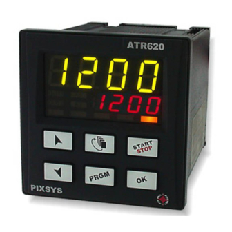
Page 9: Displays And Keys
Displays and keys 25.1 Numerical indicators (displays) Visualize usually process value (ex. Value read by thermocouple), but may also visualize setpoint value, time elapsed after cycle start , step number , percentage value of output , value of entering parameter GREEN during configuration Visualization on this dispay is programmable... -
Page 10: Leds
25.2 Leds ON when output OUT is active ON when output A1 is active ON when output A2 is active ON with cycle in progress, flashing if function “Simple controller” in progress, remote setpoint, manual control, serial communication. 25.3 Keys •... -
Page 11: Programming And Configuration
The file of this paragraph is available in the Download section at www.pixsys.net and it may be used for this purpose. Set the controller to... - Page 12 26.1.1 Programming of starting set-point (if configured) Press Display Red display shows At any time press , then to quit the programming mode and save (see configuration of modified data.. visualization Par.19, 4 digit). Green display shows the “starting setpoint”. Otherwise go to point 5.
- Page 13 26.1.2 Cycle programming (programming of steps/ segments)… Press Display Red display shows or number of step which is being modified (for a few seconds), then Red display shows time value (duration) of step. Increase / decrease the Enter duration of step value on green display as hours:minutes ** Enter...
- Page 14 26.1.3 Programming of auxiliary output (if configured) Press Display Green display shows If output A1 is not programmed as timed auxiliary, go to point 10. Select the state of auxiliary output during the step: active or for not active Green display shows If output A2 is not programmed as timed auxiliary, go back to...
-
Page 15: Start Of A Cycle
27 Start of a cycle 27.1 Cycle start and programming of delaied start Red display shows Press Display display shows available cycles Increase or decrease until the chosen cycle is visualized (for cycle no.1), (for cycle no.2)... Cycle starts. Buzzer rings. -
Page 16: Function "Fast Advancement
27.2 Function “Fast advancement” During cycle execution or in case of restart after an interruption, it may be useful to change the programmed time value of the running cycle (onwards or backwards) to meet the required setpoint. Press Display Forwards or backwards on To stop the cycle and set cycle (each beep of the controller in... -
Page 17: Function Simple Controller In Stop Mode
27.4 Function SIMPLE CONTROLLER in STOP mode. Set the controller to mode. Press Display Red display shows available options Increase until visualized Red display shows , Green display shows setpoint value. Increase or decrease Enter required setpoint setpoint value value. The controller activates the output to hold the programmed... -
Page 18: Auto-Tuning
27.5 Auto-tuning Auto-tuning function can be started if the controller is configured as SIMPLE CONTROLLER. Process value must be at least 35% lower than setpoint value (to avoid overshooting of temperature above setpoint value). If two process are enabled, please go to P-19/1 digit, to choose the process to which Autotuning will refer. -
Page 19: Activate Remote Setpoint By Serial Input
27.7 Activate remote setpoint by serial input Set the controller to mode. To start the function by serial input, write 1 at modbus address 15: this operation must be repeated at least every 8 seconds, otherwise the controller will return to mode To quit the function write 0 at the same address. -
Page 20: Manual Control Of Output
27.8 Manual control of output This functions allows to control/modify manually the command output to exclude automatical control of process. The output is activated as percentage 0 - 100% according to the time basis entered on parameter P-30 (cycle time). Set the controller to mode and follow the points below: Press... -
Page 21: Configuration For Installer
28 Configuration for installer 28.1 Modify numeric value of parameter The following options are available : 1. If all 4 digits are flashing, press to change the parameter. 2. If all 4 digits are visualized but only one is flashing, press to modify it and then to reach the following digit . - Page 22 Press Display display shows green display shows value of parameter Increase / decrease number Visualize number of parameter parameter which must be modified Green display shows the flashing value of selected parameter. Increase / decrease value Enter new value of visualized parameter. Value of parameter stops modify other...
-
Page 23: Memory Card
28.3 Memory Card Parameters and cycle data can be easily and quickly copied from one controller to other controllers using the Memory Card. The controller must be switched off before entering the Card. Please check also entry direction : the small scanning must be turned towards the back panel and the small IC must be turned towards the external side of the box. -
Page 24: List Of Configuration Parameters
29 List of configuration parameters P-01 General configuration This parameter selects the type of P.I.D. action, enables operator’s access to special functions like manual control of output percentage 0-100%, Autotuning, delayed start, operating as “Simple controller” with fixed setpoint beside standard programming function, possibility to modify cycle data during the cycle, programming of a starting setpoint (to assure the programmed rising gradient in case that kiln temperature at cycle... - Page 25 Digit – Cycles available to the operator No cycles available Remote setpoint enabled 1…9 1..8 cycles available for the operator Select 9 for 15 cycles / 20 steps each P-02 Configuration analog input AN1 Select type of thermocouple or RTD connected to input AN1, visualization range and process corresponding to this input.
- Page 26 2 Type T (-250/400°C) 3 Type R (-50/1750°C) 4 Type J (-200/1000°C) 5 Type E (-250/1000°C) Digit - Decimal point 0 No decimal point 1 Visualization with one decimal point 2 Visualization with 2 decimal points (only V /mA) 3 Visualization with 3 decimal points (only V /mA) Digit –...
- Page 27 Digit – Select remote setpoint 0 Remote setpoint by analog input AN2 Control input AN1 1 Setpoint by serial input: process 1 – word modbus 9 process 2 – word modbus 10 P-06 Lower limit setpoint 1 (-999/3000 digit) P-07 Upper limit setpoint 1 (-999/3000 digit) Selectable limits of setpoint 1 P-08...
- Page 28 Digit –Operating zone for alarm and state of contact Active “under” (independent or deviation alarm) or “inside” (band alarm), Contact N.O. Active “over” (independent or deviation alarm) or “outside” (band alarm), Contact N.O. Active “under” (independent or deviation alarm) or “inside”...
- Page 29 1 Input START at impulse (>= 150 msec) 2 Input STOP at impulse (>= 150 msec) 3 Input START/STOP at impulse (>= 150 msec) 4 RUN input when active. The controller executes the cycle programmed on 3 digit (or function selected on 4 digit) until contact is closed (or open).
- Page 30 0 Only process1 1 Only process 2 2 Add process 1 and process 2 Digit – Real time/duration of cycle 0 No 1 yes Digit – Visualization of step 0 Step number always visualized in programming mode 1 Step number visualized only at beginning of step (equivalent to the operating in programming mode of series ATR610) P-20...
- Page 31 P-25 Filter on analog inputs (1/20 averages). Value of software filter which is active on the reading of sensors connected to inputs AN1 and AN2. In case of disturbed signals, filter should be increased, reducing reading speed . P-26 Offset calibration for input AN1 (-15.0/15.0 digit) P-27 Gain calibration for input AN1 (-10.0%…+10.0%) These...
- Page 32 P-38 Derivative time (0.0/999.9 sec). (0 excludes derivative) Parameters for P.I.D. control on process 1. Dead band limits the zone where PID is not active - Proportional band refers to inertia of process and is expressed as units (ex. °C) – Integral time express inertia of process as seconds – Derivative time has a damping function and is usually ¼...
- Page 33 1 8, O, 1 2 8, E, 1 3 8, N, 2 4 8, O, 2 5 8, E, 2 Digit – Enable Modbus delay 0 Delay desabled. 1 Delay enabled (15, 12, 9, 6, 3 ms ). Digit – Enable software upgrade via serial input 0 software upgrade via serial input desabled 1 software upgrade via serial input enabled P-50...
- Page 34 Digit – Select type of degrees 0 Celsius (°C). 1 Fahrenheit (°F). Digit – Brightness display 2 0 Higher brightness. 1 Lower brightness P-52 Block of cycle programming, enable endless step and waiting function for multi-loop applications digit:modify of some or all cycles can be locked to avoid that specific programmed options are lost due to wrong programming.
-
Page 35: Alarms Operating
30 Alarms operating Three alarms can be programmed and be connected to outputs OUT, A1, A2 ( if they are not used for control). The following graphs describe the programmable operatings. Band alarm (setpoint-process) Alarm can be : Comparison value •... - Page 36 General alarm (setpoint) Alarm can be : • active over setpoint • active below setpoint Example: over above. Cycle stop and/or acoustic signal can be programmed for each type of alarm operating. Programmable timed operating ¿ (auxiliary) ON or OFF state of auxiliary output is programmable for each segment/step of the cycle.
-
Page 37: Special Software Functions
31.1 Recovery of interrupted cycle with automatic gradient Recovery function is particularly useful for temperature control on kilns. At Temperature restarting after a power failure ATR620 can resume the interrupted cycle, assuring optimal cycle execution. 4. Power failure during a rising step:... -
Page 38: Recovery Of Interrupted Cycle With Programmable Gradient
31.2 Recovery of interrupted cycle with programmable gradient restart process value (kiln Temperature temperature) is lower than setpoint value, ATR620 stops the cycle in progress and executes a rising step Recovery phase with programmable with programmable gradient gradient. Parameter 23... -
Page 39: Double Loop: Control The Gap Between Processes
32 Communication protocol Modbus RTU 32.1 Main features ATR620 has been conceived for control and communication by Terminals via Modbus RTU protocol. It is provided with serial port RS485 for programming of configuration parameters and reading of analog inputs. -
Page 40: Function Master
32.2 Function Master Software functions of ATR620 include operating as Master. This feature allows serial communication of several controllers to control more zones of the same kiln. Function is enabled entering 0 on parameter 50. Master will communicate Start/Stop of cycle and setpoint values to the connected slave units (which must be configurated for remote setpoint on parameters 1 and 5). - Page 41 Parameter 15 Parameter 16 Parameter 17 Parameter 18 Parameter 19 Parameter 20 Parameter 21 Parameter 22 Parameter 23 Reserved Parameter 25 Parameter 26 Parameter 27 Parameter 28 Parameter 29 Parameter 30 Parameter 31 Reserved Reserved Reserved Parameter 35 Parameter 36 Parameter 37 Parameter 38 Parameter 39...
-
Page 42: Error Messages
33 Error messages In case that the plant does not work properly, the controller stops the eventual cycle in progress and shows an error message for the fault condition. Example: a damaged thermocouple will be noticed with error code flashing on display1. For details see table below. Cause E-01 Programming error E ²... -
Page 43: Application On Industrial Kilns
34 Application on industrial kilns Controller ATR620 has a wide range of applications on industrial kilns, environmental chambers, furnaces, dryers… Certainly some of the most common application fields are electrical kilns for ceramics, glass, metalworking. Below some examples with a short list of main configuration parameters. - Page 44 Safety Contactor 230 Vac FUSE Controller CD 3000S CD 3000S CD 3000S Input 3-30Vdc Input 3-30Vdc Input 3-30Vdc Load Load Load Model : ATR620-21ABC THERMOCOUPLE PIXSYS P I X S Y S STAR DELTA HEATING ELEMENTS Micro-Switching OPEN DOOR AN-0017-3504...
-
Page 45: Kiln With 2 Thermocouples And Contactor Control
In this configuration two outputs of ATR620 are configured as control of two processes (corresponding to TC1 and TC2), the third is available for alarm/auxiliary/event. - Page 46 SUPPLY 230Vac JUMPER Selection Supply 230Vac Controller Model : ATR620-22ABC PIXSYS RESISTORS Zone “A” PIXSYS RESISTORS Zone “B” THERMOCOUPLE Zone “B” Micro Switching OPEN DOOR...
-
Page 47: Kiln With 4 Thermocouples - 4 Units Atr620 Configuration Master/Slave
37 Kiln with 4 thermocouples - 4 units ATR620 Configuration Master/Slave Configuration Master/Slave is suitable also for plants requiring more than two control loops. Still it is necessary to program one single unit, simplifying programming and operating. The following example describes a kiln with four control loops. Up... - Page 48 MASTER Controller SLAVE 1 SLAVE 2 SLAVE 3 Mod. : ATR620-21ABC Controller Controller Controller Mod. : ATR620-21ABC Mod. : ATR620-21ABC Mod. : ATR620-21ABC serial Line RS 485 PIXSYS PIXSYS PIXSYS PIXSYS Resistors Resistors Resistors Resistors ZONE “A” ZONE “B” ZONE “C”...
-
Page 49: Configuration Table
38 Configuration table Date: Model ATR620: Installer: Plant: Notes: P-01 General configuration P-02 Analog input AN1 P-03 Analog input AN2 P-04 Reserved P-05 Control output and source of setpoint P-06 Lower limit setpoint 1 (-999/3000 digit) Upper limit setpoint 1 (-999/3000 digit) - Page 50 P-30 Max. time for impulse zone 1 (1/120sec) P-31 Limit of control signal zone 1 (10/100%) P-32 Reserved P-33 Reserved P-34 Reserved P-35 ON/OFF hysteresis;PID dead band (-99.9/300.0digit) P-36 Proportional band (0-3000digit) P-37 Integral time (0/9999 sec). P-38 Derivative time (0.0/999.9 sec). P-39 Lower limit scale 3 (-999/3000 digit) P-40 Upper limit scale 3 (-999/3000 digit) P-41 Offset AN2 (-15.0/15.0 digit)
- Page 53 PIXSYS Via Tagliamento, 18 30030 Mellaredo di Pianiga (VE) www.pixsys.net e-mail: sales@pixsys.net - support@pixsys.net Software Rev. 1.10 2300.10.025-RevC 061004 *2300.10.025-C*...
Need help?
Do you have a question about the ATR620 and is the answer not in the manual?
Questions and answers