Pixsys ATR 121 User Manual
Hide thumbs
Also See for ATR 121:
- User manual (84 pages) ,
- User manual (43 pages) ,
- User manual (41 pages)
Table of Contents
Advertisement
Available languages
Available languages
Advertisement
Table of Contents

Related Manuals for Pixsys ATR 121


Summary of Contents for Pixsys ATR 121
-
Page 2: Table Of Contents
Contents 1 - SECTION FOR USERS ..............4 2 - DISPLAYS AND KEYS ............... 4 3 - CHANGE OF SETPOINT VALUE ............5 4 - LIST OF ERROR MESSAGES............6 5 - SECTION FOR INSTALLERS............. 6 6 - INTRODUCTION ................6 7 - ORDERING CODES................ - Page 3 Sommario 25 - SEZIONE UTENTE................ 46 26 - VISUALIZZATORI E TASTI ............46 27 - CAMBIO DEL SETPOINT ............... 47 28 - SEGNALAZIONE ANOMALIE............48 29 - SEZIONE INSTALLATORE ............49 30 - INTRODUZIONE................49 31 - COMPOSIZIONE DELLA SIGLA ............ 50 32 - CARATTERISTICHE ..............
-
Page 4: Section For Users
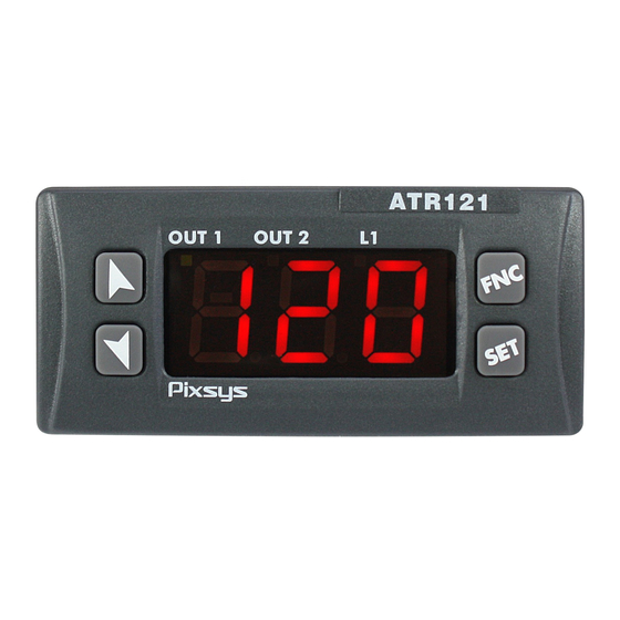
SECTION FOR USERS DISPLAYS AND KEYS Display normally shows process value (ex. measured temperature), but can also visualize setpoints or value of entering data Visualize set, increase set or scroll parameters (whith fast advancement) Visualize set, decrease set, scroll parameters. (whith fast advancement) Visualize setpoints (ex. -
Page 5: Change Of Setpoint Value
CHANGE OF SETPOINT VALUE To modify the setpoint value, press key or one of the arrow-keys: led OUT1 flashes and it is now possible to enter/modify setpoint value by pressing the arrow-keys. Press Display Display Press shows To modify setpoint (fast control advancement available). -
Page 6: List Of Error Messages
Contact technical service SECTION FOR INSTALLERS INTRODUCTION Thanks for choosing a Pixsys Controllers. Various models with 3-4 digits display make the controller suitable for a wide range of applications with temperature, humidity, pressure sensors and linear potentiometers. Output options include two relays and SSR, but the unit is configurable also as visualizer/indicator for applications not requiring control or alarm outputs. -
Page 7: Ordering Codes
ORDERING CODES Ordering codes model ATR121 ATR121- 12…24Vac ± 10% 50/60Hz Power supply 12…35Vdc 24 Vac ± 10% 50/60 Hz 230 Vac ± 10% 50/60 Hz 115 Vac ± 10% 50/60 Hz Serial RS485 - protocol Modbus RTU slave. communica Relay Q2 not available in this model, tion alarm available on SSR output. -
Page 8: Technical Data
TECHNICAL DATA Main features Displays 3 digits (0,56 inches) on ATR121 4 digits (0,40 inches) on ATR141 + 3 Leds (Out1 , Out2 , Fnc) Operating temperature 0-40°C - humidity 35..95uR% Sealing Front panel IP65 (with gasket) / Box IP30 / Terminal blocks IP20 Material ABS UL94V2 self- exstinguish Weight Approx. -
Page 9: Electrical Wirings
Sizes and installation Dima di foratura 28.5 x 70.5 mm Frontal panel cut-out Spessore suggerito ÷8 Suggested thickness 42mm 42mm inserimento insert Memory Card Memory Card 53 mm 77 mm ELECTRICAL WIRINGS Although this controller has been designed to resist the noises in an industrial environment, please notice the following safety guidelines: Separate control lines from the power wires. -
Page 10: Wiring Diagram Atr121 / Atr141
WIRING DIAGRAM ATR121 / ATR141 10 - PIXSYS ATRxxx- xxT PIXSYS ATRxxx-xx 2 wir e 4 /2 0m A 2 wire 4 /2 0mA Po we r Po we r V/ I V/ I 10A 230V 10A 230V 5A 230V... - Page 11 For thermoresistances PT100, NI100 • For a three-wires PT100 use cables with the same diameter • For a two-wires PT100 short-circuit terminals 10 and 12. WHITE For thermoresistances NTC, PTC, PT500, PT1000 e potentiometers For linear signals V/mA • Comply whit polarity Examples of connection for linear input 10.4 For signals 0…10V...
- Page 12 For signals 0/4…20mA with external power of sensor Comply with polarity B= sensor ground C= sensor output For signals 0/4…20mA with two-wires sensors Comply with polarity A= sensor supply Check power supply requirements on technical data sheet of sensor! Capacity 12…24V / 30mA for models AD Capacity 8V / 20mA for models A-B-C C= sensor output Relay outputs...
-
Page 13: Alarm Intervention Modes
Serial communication 10.7 Models ATR121-xT , ATR141-xT RS485, protocol MODBUS-RTU Do not use LT (line termination) resistors ALARM INTERVENTION MODES 11 - Absolute Alarm or Threshold Alarm ( 11.1 selection) Absolute alarm with controller in heating Alarm Spv functioning Hysteresis parameter (Par.11 selected... - Page 14 Absolute Alarm or Threshold Alarm Referring to 11.2 Setpoint Command ( selection ) Absolute alarm refers to Comand Spv the command set, with the Hysteresis parameter controller in heating > 0 functioning Alarm Spv (Par.11 selected ) and hysteresis Time (absolute value) The command set can be Alarm...
- Page 15 Upper Deviation Alarm ( selection) 11.4 Upper deviation alarm value of alarm setpoint Alarm Spv greater than “0” and Hysteresis parameter hysteresis value greater > 0 than“0” (Par.23 > 0) Comand Spv N.B.: hysteresis value can’t Time be less than “0” Alarm output Upper deviation alarm...
- Page 16 Lower Deviation Alarm ( selection) 11.5 Lower deviation alarm value of alarm setpoint Comand Spv greater than “0” and Hysteresis hysteresis value greater parameter > 0 than “0” (Par.23 > 0). Alarm Spv Time N.B.: hysteresis value can’t Alarm be less than “0” output Lower deviation alarm Hysteresis...
-
Page 17: Modify Configuration Parameters
MODIFY CONFIGURATION PARAMETERS 12 - The configuration menu of the unit is password protected to prevent unauthorised access to the instrument set-up. Password cannot be modified. Press Display After 5 seconds display shows , first digit on the left is flashing. on ATR141 Increase first digit to “1”... -
Page 18: Configuration Parameters
CONFIGURATION PARAMETERS 13 - Range Display Description Description ATR121 ATR141 Select type Control Q1 of control Alarm Q2 ATR121 (default) output Control Q1 ATR141 Alarm SSR Control SSR Alarm Q1 Control Q2 Alarm Q1 Open Q1 Close Q2 (SSR on versions with RS485) Select type TC type K... - Page 19 Pt1000 -100…600°C 0…10V 0…20mA 4…20mA Potenziometer ≤ 6KΩ Potenziometer ≤150KΩ Select no decimal point position (default) decimal point 1 decimal point 2 decimal points ----------- 3 decimal points Lower limit -199.. -999.. Degrees for selectable for +999 +9999 temperature setpoint digit digit sensors Digits...
- Page 20 Lower limit -199… -999… (default 0) signals V/mA +999 +9999 Example: for digit digit input 4…20mA, enter on this parameter the value corresponding to 4mA Upper limit -199… -999… (default 999) signals V/mA +999 +9999 Example: for digit digit input 4…20mA, enter on this parameter the...
- Page 21 Offset -19.9… -99.9… Tenths of degree ATR121 calibration. +99.9 +99.9 for temperature. This value is units units Digits for linear signals and added to the process potentiometers ATR141 value (default 0.0) visualized on display (usually correcting the ambient temperature) Gain -19.9% -99.9% (default 0.0)
- Page 22 Type of Heating (N.O.) control (default) Cooling (N.C.) Absolute alarm with manual reset of contact Absolute alarm with manual reset; status of relay stored in case of switch- Heating mode with PID set to 0 if process value is above setpoint value Type of Open contact...
- Page 23 Proportional 0 = On/Off band 0…999 0…9999 °C (temp.) Width of the digit (V/mA) process (default 0) expressed as units (°C if temperature) Integral time. seconds Inertia of the 0-999 0-9999 (0 excludes process Integral) expressed as (default 0) seconds Derivative time for 0…999 0…9999 seconds...
- Page 24 Operating Absolute related mode of to process alarm. /Treshold alarm Setpoint for (default) alarm is Band alarm SET2 Deviation high Deviation low Absolute related to setpoint 1 Command output for cooling action for PID Heating/Cooling mode Absolute – with manual reset (after alarm activation, press FNC key to reset...
- Page 25 Absolute with manual reset (after alarm activation, press FNC key to reset the output) ; status of relay stored in case of switch-off State of Normally open, contact for active at Start alarm output (default) and type of Normally closed, operating active at Start Normally open,...
- Page 26 ATR121 Alarms -199… -999… Tenth of degree hysteresis +999 +9999 for temperature digits digits sensor. Digits for ATR141 linear signals potentiometers (default 0.0) ATR121 Alarm delay -180…+180 seconds Negative: delay at alarm ATR141 deactivation Positive: delay at alarm activation (default 0) Allow/deny Allow modification...
- Page 27 ATR121 Select type Disabled of auto- (default) tuning automatic ATR141 manual start of Tuning ATR121 Select Double setpoint operating (default) mode and Single setpoint visualization ATR141 Indicator only (no options relay output) Function Neutral zone/Dead band Hide process and setpoint values Domotics 1 : switch off...
- Page 28 Single setpoint: setpoint always visualized on display. Press to visualize process value (flashing) ATR121 Type of Celsius (default) degree Fahrenheit ATR141 ATR121 Baud rate of 300 bit/s serial 9600 bit/s communication 19200 bit/s ATR141 (default) 38400 bit/s ATR121 Slave 1-254 (default 254) address ATR141...
- Page 29 this Water Set TC2 as 2s remark 1 parameter, and P.B.M as 2.50. will assume one of the listed values Proportional 1.00 … 5.00 Proportional band band for cooling multiplier for is given by the remark 1 cooling value of action (parameter 15) multiplied for the...
-
Page 30: Tuning
Filter applied Filter desabled (default) visualization Enable filter of of process. first order (time This filter can const. 1s). slow down Mean on 2 samples the refresh of Mean on 3 samples value on Mean on 4 samples display in Mean on 5 samples order to simplify the... -
Page 31: Manual Start Of Tuning
MANUAL START OF TUNING 15 - Select parameter (manual start) Press Display Display shows Display shows Display will show To interrupt the process value and function press alternately until wait for 4 press to select the function is seconds. completed (it may take a few minutes). -
Page 32: Function Latch On
FUNCTION LATCH ON 17 - application with linear potentiometers (potentiometer ≤ 6K) and (potentiometer ≤ 150K) or 0…10Volt , 0/4…20mA inputs, the lower limit of scale (see parameter ) can be set to minimum position of sensor; it is also possible to set the upper limit of scale (parameter ) to the max. - Page 33 Store max. value To quit standard Display shows proceeding press To enter “virtual zero” set the sensor to zero point. Store virtual zero. To interrupt the function Display shows press ** If is selected, at starting repeat calibration on point 4. ZERO...
-
Page 34: Function Neutral Zone
FUNCTION NEUTRAL ZONE 18 - The Neutral Zone function (which can be enabled selecting on parameter 28 ) allows the setting of a neutral zone control action as described in the graph. In Heating mode (parameter selected as ), the operating treshold for control relay will be the value resulting from SET1 minus SET2, and the operating treshold for alarm relay will be SET1 plus SET2 (hysteresis is always set via parameter... -
Page 35: Serial Communication
SERIAL COMMUNICATION 19 - Serial communication RS485 and protocol MODBUS – RTU enable the controller ATR121/141 to receive and exchange data, allowing the connection of more units to a centralized supervisory system. The device can be configured only as Slave unit. LT (line termination) resistors on RS485 line must be removed to avoid anomalies. - Page 36 MODBUS READ/ RESET ADDRESS WRITE VALUE DESCRIPTION Type of device 101/10 Software version Reserved Reserved Reserved Slave Address EEPR Reserved Loading default values (write 9999) R/W 0 1000 Process value 1001 Cold junction value 1002 Value Setpoint 1 R/W EEPR 1003 Value Setpoint 2 R/W EEPR...
- Page 37 1=controller in START 1010 OFF LINE time (milliseconds) R/W 0 2001 R/W EEPR Parameter 1 2002 R/W EEPR Parameter 2 2003 R/W EEPR Parameter 3 2004 R/W EEPR Parameter 4 2005 R/W EEPR Parameter 5 2006 R/W EEPR Parameter 6 2007 R/W EEPR Parameter 7...
- Page 38 2019 R/W EEPR Parameter 19 2020 R/W EEPR Parameter 20 2021 R/W EEPR Parameter 21 2022 R/W EEPR Parameter 22 2023 R/W EEPR Parameter 23 2024 R/W EEPR Parameter 24 2025 R/W EEPR Parameter 25 2026 R/W EEPR Parameter 26 2027 R/W EEPR Parameter 27...
-
Page 39: Memory Card (Optional)
MEMORY CARD (OPTIONAL) 20 - Parameters and setpoint values can be easily copied from one controller to others using the MEMORY CARD. The controller must be switched-off before entering the Card. Check also entry direction (components must be turned towards front panel). - Page 40 Memory C.243 with battery (OPTIONAL) 20.1 With the controller not connected to power supply. The memory card is equipped with an internal battery with an autonomy of about 1000 uses. Insert the memory card and press the programming buttons. When writing the parameters, the led turns red and on completing the procedure it changes to green.
-
Page 41: Loading Default Values
LOADING DEFAULT VALUES 21 - This procedure makes it possible to restore factory settings of the instrument. Premere Effetto Eseguire After 5 seconds display shows , first digit for 3 on the left is flashing. seconds. on ATR141 Change the flashing Enter password: digit and move to the for ATR121... - Page 42 SUPERVISORY SYSTEM WITH CONTROLLERS 22 - ATR121 / 141 Below main elements of the system. Consider the converter RS232/RS485 with automatic direction and the suggested serial communication cables. Sensor : PT100 RS485 RS485 RS485 SLAVE 1 SLAVE 2 SLAVE 254 Controller Controller Controller...
-
Page 43: Configuration Memorandum
CONFIGURATION MEMORANDUM 23 - Date: Model ATR121/141: Installer: Plant: Notes: Par. Description Default Prom. Select type of command output Sensor Type Visualization of decimal point Lower limit of setpoint Upper limit of setpoint ATR121 ATR141 Lower limit only for V/I V/mA Upper limit only for V/I V/mA Latch On Function Offset calibration... - Page 44 State of contact for alarm output in case of anomaly State of the LED Alarms hysteresis delay alarm Set protection. Software filter Type of autotuning Type of operating Degrees selection Baud rate address slave Serial delay Cooling fluid Proportional band multiplier Overlapping / dead band Cycle time 2 Visualization Filter...
-
Page 45: Notes / Update
NOTES / UPDATE 24 -... -
Page 46: Sezione Utente
SEZIONE UTENTE 25 - VISUALIZZATORI E TASTI 26 - Visualizza normalmente il processo (es.: Temperatura sonda), ma può visualizzare anche il valore dei setpoint (punti d’intervento) oppure i dati in inserimento. ATR121 Visualizza il set, incrementa OUT 1 OUT 2 il set o scorre i parametri (con avanzamento veloce). -
Page 47: Cambio Del Setpoint
CAMBIO DEL SETPOINT 27 - Per modificare il valore impostato premere il tasto volta, o premere uno dei tasti freccia; il led OUT1 lampeggia, è quindi possibile impostare un nuovo valore con le frecce. Premere Effetto Eseguire Il display Premere uno dei tasti visualizza il oppure per modificare il valore di... -
Page 48: Segnalazione Anomalie
SEGNALAZIONE ANOMALIE 28 - In caso di mal funzionamento dell’impianto, il regolatore attiva i relè, come da parametri 12 e 21 e segnala il tipo di anomalia riscontrata. Per esempio il regolatore segnalerà la rottura di una eventuale termocoppia collegata visualizzando (lampeggiante) sul display. -
Page 49: Sezione Installatore
LATCH ON velocizza la taratura della macchina. Come sulla più recente strumentazione Pixsys sono disponibili Memory-card per la configurazione in serie e per lo storico degli impianti. Seguendo le tabelle sottostante si può... -
Page 50: Composizione Della Sigla
COMPOSIZIONE DELLA SIGLA 31 - Composizione della sigla Modello ATR121 ATR121- xx x Alimentazione 12…24Vac ±10% 50/60Hz 12…35Vdc 24 Vac ±10% 50/60 Hz 230 Vac ±10% 50/60 Hz 115 Vac ±10% 50/60 Hz Seriale A Rs485 con protocollo Modbus RTU slave. In queste versioni non è... -
Page 51: Caratteristiche
CARATTERISTICHE 32 - Caratteristiche generali Display 3 display (0,56 pollici) su ATR121 4 display (0,40 pollici) su ATR141 + 3 led (Out1 , Out2 , Fnc) Temperatura di 0-40°C - umidità 35..95uR% esercizio Protezione Pannello frontale IP65 (con guarnizione) / Contenitore IP30 / Morsettiere IP20 Materiale Policarbonato UL94V0 autoestinguente Peso ca. - Page 52 Caratteristiche software Algoritmo di On/OFF con isteresi o P.I.D. con Autotune regolazione Protezione dati Parametri sotto password programmazione veloce da memory-card Dimensioni e installazione 32.1 Dima di foratura 28.5 x 70.5 mm Frontal panel cut-out Spessore suggerito ÷8 Suggested thickness 42mm 42mm inserimento...
-
Page 53: Collegamenti Elettrici
Evitare la vicinanza di gruppi di potenza, in particolare se a controllo di fase. SCHEMA DI COLLEGAMENTO ATR121 / ATR141 34 - PIXSYS ATRxxx- xxT PIXSYS ATRxxx- xx 2 wir e 4 /2 0mA... - Page 54 AN1 Ingresso analogico 34.3 Per termocoppia K, S, R, J; • Rispettare le polarità • Per eventuali prolunghe utilizzare cavo e morsetti compensati adatti alla termocoppia utilizzata. (solo per modelli AD) Per un corretto funzionamento dello strumento, utilizzare sonde isolate da terra. In caso contrario, utilizzare singolo trasformatore isolato per ogni strumento.
- Page 55 Esempi di connessione per ingressi normalizzati 34.4 Per segnali normalizzati in tensione 0…10V Rispettare le polarità Ri>=110KΩ Per segnali normalizzati in corrente 0 ÷ 20mA oppure 4 ÷ 20mA con sensori a tre fili. Rispettare le polarità A= alimentazione sensore Verificare la compatibilità...
- Page 56 Uscite a relè 34.5 Q1 con contatti : 8A/250V~ (Su versioni • A-B-C)per carichi resistivi (manovre 2x10 5 min a 8A /250V~) Q1 con contatti : 10A/250V~ (Su versioni • AD)per carichi resistivi (manovre 2x10 5 min a 10A /250V~) Q2 con contatti : 5A/250V~ per carichi •...
-
Page 57: Modi D'intervento Allarme
MODI D’INTERVENTO ALLARME 35 - Allarme assoluto o allarme di soglia (selezione 35.1 Allarme assoluto con regolatore in Alarm Spv funzionamento caldo. Hysteresis Par.11 selezionato parameter > 0 e isteresi (valore assoluto) Time Alarm output Time Allarme assoluto con regolatore in Hysteresis funzionamento freddo. - Page 58 Allarme assoluto o allarme di soglia riferito al 35.2 setpoint di comando (selezione Allarme assoluto riferito al Comand Spv set di comando, con Hysteresis parameter regolatore in funzionamento > 0 caldo. Alarm Spv Par.11 selezionato e isteresi (valore assoluto) Time Il set di comando può...
- Page 59 Allarme deviazione superiore (selezione 35.4 Allarme di deviazione superiore valore di setpoint Alarm Spv allarme maggiore di “0” e Hysteresis valore di isteresi maggiore di parameter > 0 “0” (Par.23 > 0). Comand Spv N.B.: il valore dell’isteresi non può essere minore di 0 Time Alarm output...
-
Page 60: Modifica Parametri Di Configurazione
Allarme deviazione inferiore (selezione 35.5 Allarme di deviazione inferiore valore di setpoint Comand Spv allarme maggiore di “0” e Hysteresis valore di isteresi maggiore parameter > 0 di “0” (Par.23 > 0). N.B.: il valore dell’isteresi Alarm Spv Time non può essere minore di Alarm output Hysteresis... - Page 61 Premere Effetto Eseguire Il display dopo circa 5 secondi visualizza con la prima cifra da sinistra lampeggiante. Nel caso del ATR141 Incrementare la prima Premere cifra al valore “1”. passare alla cifra successiva ed inserire la password di configurazione “123” o “1234”...
-
Page 62: Tabella Parametri Di Configurazione
TABELLA PARAMETRI DI CONFIGURAZIONE 37 - N Display Descrizione Range di inserimento Parametri ATR12 ATR141 Descrizione Comando Q1 1 ATR121 Selezione Allarme Q2 tipo uscita di (Default) comando Comando Q1 Allarme SSR ATR141 Comando Allarme Q1 Comando Q2 Allarme Q1 Apri Q1 Chiudi Q2 (SSR se vers. - Page 63 contrario, Ntc 10KΩ - utilizzare 40…125 °C singolo Ptc 1KΩ trasformatore 50…150 °C isolato per ogni Pt500 – strumento. 100…600 °C Pt1000 – 100…600 °C 0…10V 0…20mA 4…20mA Potenziometro ≤ 6KΩ fondo scala Potenziometro ≤ 150KΩ fondo scala Seleziona il tipo No decimale di decimale (Default)
- Page 64 Limite superiore -199… -999… Valore in gradi impostabile per +999 +9999 per sensori di temperatura e il setpoint digit per sensori normalizzati e potenziometri. (Default: 999 per ATR121 e 1750 per ATR141) Limite inferiore -199… -999… Valore in digit range solo per +999 +9999 (Default 0)
- Page 65 automatica limiti Zero virtuale ATR141 memorizzato Zero virtuale potenziometri start lineari e ingressi normalizzati) Definisce la -19.9… -99.9… Valore in decimi 9 ATR121 correzione +99.9 +99.9 di grado per sensori di offset sulla temperatura e visualizzazione digit per sensori dell’ingresso ATR141 normalizzati e sensore.
- Page 66 Tipo Caldo (N.A.) regolazione (Default) Freddo (N.C.) Allarme assoluto con riarmo manuale Allarme assoluto con riarmo manuale e memoria stato relè in caso di spegnimento Caldo con PID sempre a 0 se il processo è sopra il set. Stato del Sicurezza a contatto di contatto aperto.
- Page 67 Isteresi in -199… -999… Valore in decimi 14 ATR121 ON/OFF o +999 +999 di gradi per sensori di banda morta in temperatura e P.I.D. dell’uscita digit per sensori di comando ATR141 normalizzati e potenziometri. (Default 0.0) Banda 0…999 0…9999 0 = On/Off proporzionale Valore in gradi Inerzia del...
- Page 68 Definisce la 1-300 Secondi. durata del ciclo Impostando 0 il tempo di ciclo per l’uscita a diventa 100ms tempo (Default 10) proporzionale (per contattori normalmente superiore a 10, per SSR normalmente a 1, per valvole motorizzate valore dichiarato da produttore) Modalità...
- Page 69 Assoluto con riarmo manuale. Dopo l’attivazione dell’allarme l’uscita viene sbloccata premendo il tasto FNC sul frontale Assoluto con riarmo manuale e memoria stato relè in caso di spegnimento. Dopo l’attivazione dell’allarme l’uscita viene sbloccata premendo il tasto FNC sul frontale Contatto uscita Normalmente allarme e tipo...
- Page 70 Normalmente chiuso attivo al raggiungimento dell’allarme Stato del Sicurezza a contatto contatto aperto. (Default) dell’uscita di Sicurezza a allarme in caso contatto chiuso. di guasto ATR121 Definisce lo Acceso a stato del led contatto aperto. OUT2 in Acceso a corrispondenza ATR141 contatto chiuso.
- Page 71 Protezione set. Entrambi i set Consente o modificabili. (Default) inibisce la Protezione set di modifica dei comando SPV1 setpoint da Protezione set di tastiera allarme SPV2 Protezione di entrambi i set. ATR121 Filtro software. 1-15 Numero di Numero di medie. Campionamento letture per il ATR141...
- Page 72 Demotica 1 : spegne il display e i led dopo 15” dall’ultima azione sui tasti Demotica 2 : spegne solo il display dopo 15” dall’ultima azione sui tasti. Demotica 3 : spegne il display (ma non il punto decimale) dopo 15” dall’ultima azione sui tasti.
- Page 73 ATR121 Indirizzi slave 1-254 (Default 254) ATR141 ATR121 Ritardo seriale 0-100 Millisecondi (Default 20) ATR141 Atr121 In modalità PID Imposta TC2 a Aria Caldo/freddo 10s e P.B.M a definisce il fluido di 1.00. (Default) raffreddamento: Imposta TC2 a Atr141 Olio modificando 4s e P.B.M a questo parametro...
- Page 74 Tempo ciclo per 1…300 Secondi l’uscita di (Default 10) Vedi raffreddamento. nota 1 Filtro in Filtro disabilitato. visualizzazione del (Default) processo. Abilitato filtro del Rallenta il refresh primo ordine del valore di (cost. di tempo processo 1s). visualizzato per Media su 2 facilitarne la lettura campioni.
-
Page 75: Tuning
TUNING 38 - L’operazione di tuning consente di calcolare i parametri PID al fine di ottenere una buona regolazione. Ciò significa controllo stabile della temperatura/processo setpoint senza fluttuazioni e risposta veloce alle deviazioni dal setpoint causate da disturbi esterni. L’operazione di tuning prevede il calcolo ed il settaggio dei seguenti parametri: •... -
Page 76: Lancio Del Tuning Manuale
LANCIO DEL TUNING MANUALE 39 - Il parametro impostato su Premere Effetto Eseguire Il display visualizza Il display visualizza Il display visualizza Per terminare alternativamente il anticipatamente la processo e la scritta procedura, premere attendere fino al e il tasto completamento della secondi. -
Page 77: Tecnica Di Tuning Automatico
TECNICA DI TUNING AUTOMATICO 40 - Il tuning automatico (parametro impostato su ) si attiva all’accensione dello strumento o quando viene modificato sensibilmente il setpoint. Il display visualizza alternativamente il processo e la scritta fino al completamento della procedura (può durare qualche minuto). - Page 78 Per la procedura di taratura fare riferimento alla seguente tabella: Premere Effetto Eseguire Esce dalla configurazione Posizionare il sensore parametri. sul valore minimo di Lo strumento visualizza funzionamento alternativamente il processo (associato a e la scritta Fissa il valore sul minimo. Posizionare il sensore sul valore massimo di Il display visualizza...
-
Page 79: Funzione Banda Morta
ZERO FUNZIONE BANDA MORTA 42 - La funzione Banda Morta (abilitata impostando parametro 28 ) permette di eseguire una regolazione detta appunto di “banda morta” (vedi figura).In funzionamento caldo (parametro impostato su ), la soglia di intervento del relè di comando sarà data da SET1-SET2 (con isteresi impostata sul parametro ), mentre la soglia di intervento del relè... -
Page 80: Comunicazione Seriale
COMUNICAZIONE SERIALE 43 - L’ATR121/141 con RS485 è in grado di ricevere e trasmettere dati via seriale tramite protocollo MODBUS RTU. Il dispositivo può essere configurato solo come Slave. Questa funzione permette il controllo di più unità ATR121/141 collegandole ad un sistema di supervisione. - Page 81 MODBUS READ/ RESET ADDRESS WRITE VALUE DESCRIZIONE Tipo dispositivo 101/10 Versione software Riservato Riservato Riservato Address Slave EEPR Riservato Caricamento valori di default (scrivere R/W 0 9999) 1000 Valore processo 1001 Valore giunto freddo 1002 Valore Setpoint 1 R/W EEPR 1003 Valore Setpoint 2 R/W EEPR...
- Page 82 1=regolatore in START 1010 Tempo OFF LINE (millisecondi) R/W 0 2001 R/W EEPR Parametro 1 2002 R/W EEPR Parametro 2 2003 R/W EEPR Parametro 3 2004 R/W EEPR Parametro 4 2005 R/W EEPR Parametro 5 2006 R/W EEPR Parametro 6 2007 R/W EEPR Parametro 7...
- Page 83 2019 R/W EEPR Parametro 19 2020 R/W EEPR Parametro 20 2021 R/W EEPR Parametro 21 2022 R/W EEPR Parametro 22 2023 R/W EEPR Parametro 23 2024 R/W EEPR Parametro 24 2025 R/W EEPR Parametro 25 2026 R/W EEPR Parametro 26 2027 R/W EEPR Parametro 27...
-
Page 84: Memory Card (Opzionale)
MEMORY CARD (OPZIONALE) 44 - E’ possibile duplicare parametri e setpoint da un regolatore ad un altro mediante l’uso della Memory Card. Inserire la Memory Card con regolatore spento facendo attenzione al verso di inserimento (componenti verso il frontale). Accendendo il regolatore il display visualizza Preme Effetto Eseguire... - Page 85 Memory C.243 con batteria (OPZIONALE) 44.1 Con regolatore non connesso all’alimentazione: La memory card è dotata di batteria interna con autonomia per circa 1000 utilizzi. Inserire la memory card e premere il tasto di programmazione. Durante la scrittura dei parametri il led si accende rosso, al termine della procedura si accende verde.
-
Page 86: Caricamento Valori Di Default
CARICAMENTO VALORI DI DEFAULT 45 - Questa procedura permette di ripristinare le impostazioni di fabbrica dello strumento. Premere Effetto Eseguire Il display dopo circa 5 secondi visualizza per 3 con la prima secondi. cifra da sinistra lampeggiante. nel caso del ATR141 Si modifica la cifra Inserire la password:... -
Page 87: Supervisione Con Atr121 / 141
SUPERVISIONE CON ATR121 / 141 46 - Esempio di sistema di controllo con supervisione e regolatori ATR121-AT. Sono evidenziati gli elementi del sistema, far attenzione in particolare al convertitore Rs232 / Rs485 con Dir. Automatico, e alla tipologia di cavo per rete dati. -
Page 88: Promemoria Configurazione
PROMEMORIA CONFIGURAZIONE 47 - Data: Modello ATR121/141: Installatore: Impianto: Note: Par. Descrizione Default Prom. Tipo uscita comando Tipo di sensore Tipo di decimale Limite inferiore setpoint Limite superiore setpoint ATR121 ATR141 Limite inferiore range per V/I V/mA Limite superiore range per V/I V/mA Funzione Latch On Calibrazione offset... - Page 89 Stato allarme in caso di guasto Stato del led Isteresi allarmi Ritardo allarme Protezione set. Filtro software. Selezione auto-tuning Selezione funzionamento Selezione gradi Baud rate Indirizzi slave Ritardo seriale Liquido refrigerante Moltiplicatore di banda proporzionale Sovrapposizione / Banda morta Tempo ciclo 2 Filtro in visualizzazione...
-
Page 90: Note / Aggiornamenti
NOTE / AGGIORNAMENTI 48 -... -
Page 91: Identification Du Modèle
IDENTIFICATION DU MODÈLE 49 - Modèle ATR121 ATR121- 12…24Vac ±10% 50/60Hz Alimentation 12…35Vdc 24 Vac ±10% 50/60 Hz 230 Vac ±10% 50/60 Hz 115 Vac ±10% 50/60 Hz Seriale A RS485 avec protocole Modbus RTU Slave. Relais Q2 n’est pas disponible dans cette version et la fonction alarme est interdite. -
Page 92: Données Techniques
DONNÉES TECHNIQUES 50 - Caractéristiques générales Affichage 3 digits (0,56 pouces) ATR121 4 digits (0,40 pouces) ATR141 + 3 indicateurs lumineux (Out1 , Out2 , Fnc) Température 0-40°C - humidité 35..95uR% ambiante Protection Façade IP65 (avec garniture) / Boîte IP30 / Raccordements électriques IP20 Matière Polycarbonate UL94V2 auto-extinguible Poids ca. - Page 93 Sorties 2 Relais + SSR: OUT1: 10A charge résistive modèle AD , 8A charge résistive modèles avec trasformateur OUT2: 5A charge résistive. SSR:8 Volt 20mA version A/B/C. 15Volt 30mA version AD (alim. 12Vac) 30Volt 30mA version AD (alim. 24Vac) Caractéristiques logiciel Algorithmes ON/OFF avec hystérésis ou P.I.D.
-
Page 94: Raccords Électriques
Dimensions et installation 50.1 Trou de panneau 70.5 x 28.5 mm épaisseur suggérée 2 - 8 mm Carte de mémoire 53 mm 77 mm RACCORDS ÉLECTRIQUES 51 - Bien que ce régulateur ait été conçu pour résister aux interférences des environnements industriels, il est prudent de suivre les précautions suivantes: Distinguer la ligne d’alimentation et la ligne de puissance... - Page 95 NOTE / AGGIORNAMENTI 48 -...
- Page 96 NOTE / AGGIORNAMENTI 48 -...
- Page 97 NOTE / AGGIORNAMENTI 48 -...
- Page 98 NOTE / AGGIORNAMENTI 48 -...
Need help?
Do you have a question about the ATR 121 and is the answer not in the manual?
Questions and answers