Pixsys ATR 121 User Manual
Hide thumbs
Also See for ATR 121:
- User manual (99 pages) ,
- User manual (84 pages) ,
- User manual (84 pages)
Table of Contents
Advertisement
Advertisement
Table of Contents

Related Manuals for Pixsys ATR 121


Summary of Contents for Pixsys ATR 121
- Page 1 ATR 121-141 Controller User manual...
-
Page 3: Table Of Contents
Summary Safety guide lines ................5 Model identification ................6 Technical data ..................6 General features ..............6 Hardware features ................7 Software features ..............8 Dimensions and installation ............8 Electrical wirings .................9 Wiring diagram ...............9 Display and keys functions .............13 Numeric indicators (Display) ..........13 Meaning of status lights (Led) ...........13 Keys ...................13 Controller functions .................14 Modifying main setpoint and alarm setpoint values..14... - Page 4 ATR121/141 - Manuale d’uso...
-
Page 5: Safety Guide Lines
, while LATCH ON function speeds up the device calibration when linear potentiometers are used. As on the latest Pixsys instrumentation, the configuration is further simplified by the Memory cards which are provided with internal battery and therefore do not require cabling to power the controller. -
Page 6: Model Identification
Model identification ATR121-141 12..24Vac ±10% 50/60Hz 12..35Vdc ATR121-141 24 Vac ±10% 50/60 Hz ATR121-141 230 Vac ±10% 50/60 Hz ATR121-141 115 Vac ±10% 50/60 Hz ATR121-141 ADT 12..35Vdc + RS485 Relay Q2 not available, alarm function available on SSR output. Technical features 3.1 General features 3 displays (0,56 inch) on ATR121... -
Page 7: Hardware Features
Hardware features An1. Configurable via Tolerance (25°C) software. Thermocouple +/-0.5 % ± 1 digit (full type: K, S, R, J. Automatic scale) for thermocouple compensation of cold input, thermo- junction from 0°C to resistance and V/mA. 50°C. Analogue Cold junction accuracy Thermoresistance: inputs 0.2°C/°C... -
Page 8: Software Features
4.1 Software features Regulation ON-OFF with hysteresis. algorithms P, PI, PID, PD with proportional time Proportional band 0..999°C or °F Integral time 0..999s (0 excludes integral function) Derivative time 0..999s (0 excludes derivative function) Manual or automatic Tuning, configurable Controller alarm, protection of command and alarm functions setpoints, heating/cooling PID function. -
Page 9: Electrical Wirings
Electrical wirings Although this controller has been designed to resist electromagnetic interferences in industrial environments, please observe following safety guidelines: • Separate control line from power wires. • Avoid proximity of remote control switches, electromagne- tic contactors, powerful engines and in all instances use specific filters. • Avoid proximity of power groups, especially those with phase control 6.1 Wiring diagram Models: ATR121-AD / ADT and ATR141-AD / ADT... - Page 10 An1 Analogue Input For thermocouples K, S, R, J. • Comply with polarity • For possible extensions, use compensated cable and terminals suitable for the thermocouples Shield/Schermo used(compensated) • When shielded cable is used, it should be grounded at one side only (only for models: AD / ADT) For a correct functioning of the device, use sensors insulated from the ground.
- Page 11 For linear signals V/mA Shield/Schermo • Comply with polarity • When shielded cable is used, it should be grounded at one side only Examples of connection for linear input For signals 0….10V 0...10V • Comply with polarity For signals 0/4….20mA with three-wire sensor • Comply with polarity 0/4...20mA C = Sensor output B = Sensor ground A = Sensor power supply (12V/30mA) PRESSURE TRANSMITTER...
- Page 12 Serial input RS485 Modbus RTu communication Do not use LT (line termination) resistors Shield/Schermo • For networks with more than five instruments supply in low voltage Relay outputs Capacity: • Q1 (ATR121/141 A-B-c): 8A, 250Vac, resistive loads, 10 operations • Q1 (ATR121/141 AD/ADT): 10A, 250Vac, resistive loads, 10 operations • Q2 (not on ATR121/141 ADT): 5A, 250Vac,...
-
Page 13: Display And Keys Functions
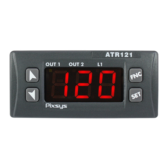
Display and keys functions 7.1 numeric indicators (Display) 1234 Normally displays the process. 7.2 Meaning of status lights (Led) ON when command output is active. When 2 OuT1 it flashes, display shows the command output setpoint (which can be modified by arrow keys). ON when alarm output is active. -
Page 14: Controller Functions
• Allows to increase main stepoint. • During configuration it allows to scroll through parameters and to modify them togheter with • If pressed after , it allows to increase the setpoints (command with OUT1 flashing/ alarm with OUT2 flashing). • If pressed once it allows to visualize the command setpoint. • If pressed twice it allows to visualize the alarm setpoint. • Allows to modify configuration parameters. • Allows to run the manual Tuning function. • Allows to enter/exit from configuration. controller functions 8.1 Modifying main setpoint and alarm setpoint values... -
Page 15: Tuning
Tuning Tuning procedure allows to calculate PID parameters to obtain a good regulation. It means a stable control of temperature/ process on setpoint without fluctuations and fast response to deviations from setpoint caused by external noises. Tuning procedure includes calculation and setting of the following parameters: • Proportional band (system inertia in °C if temperature). -
Page 16: Automatic Tuning
Confi rming with , the controller loads the new data and starts again. Pressing display shows m-no and the controller starts keeping values unchanged. PIXSYS Memory Card (optional) Memory Card (optional) Cod. 2100.30.005 with battery/con batteria Cod. 2100.30.003... -
Page 17: Latch On Function
• With the controller not connected to power supply: The memory card is equipped with an internal battery with an autonomy of about 1000 operations (button battery 2032, replaceable). Insert the memory card and press the programming button . When writing the parameters, the led turns red and on completing the procedure it turns green. - Page 18 Press Display Exit parameters Place the sensor on confi guration. minimum operating Device visualizes value (associated with alternately process Lo. n) and Lat Place the sensor on Set the value on maximum operating minimum. value (associated with Display shows Lo Hi.
-
Page 19: Dual Action Heating-Cooling
9.6 Dual action Heating-cooling The ATR121/141 is suitable also for systems requiring a combined heating-cooling action. Command output must be configured as Heating PID (par.11 reG. = Hea | Heat and par. 15 p.b. greater than 0), and one of the alarm must be configured as cooling action (par. - Page 20 x = COOL x = COOL x = COOL < 0 < 0 < 0 (HEAT) (HEAT) (HEAT) ACTIVE COMMAND OUTPUT (HEAT) ACTIVE COMMAND OUTPUT (HEAT) COMMAND OUTPUT (HEAT) ACTIVE ACTIVE ALARM OUTPUT (COOL)
-
Page 21: Dead Band Function
time t.c.2 basing on the type of cooling fluid: co.f | coo.f cooling fluid type P.b.m t.c.2 1.00 1.25 Water 2.50 Dead band function The dead band function (enabled selecting F.b.M on par. 28 FNc | Func.) creates a band within which the relays are both open or closed. -
Page 22: Serial Communication
Serial communication ATR121/141 is equipped with RS485, it can receive and broadcast data via serial communication using MODBUS RTU protocol. The device can be configured only as Slave. This function enables the control of multiple devices connected to a supervisory system. The RS485 line must be free of LT termination resistances to avoid malfunctions. - Page 23 list below includes available addresses: RO = Read Only R/W = Read/Write WO = Write Only MoDBus Read Reset Description Address Write value Device type R 101/102 Software version Reserved Reserved Reserved Slave Address EEPR Reserved Loading default values (write 9999) 1000 Process 1001...
- Page 24 1009 Start/Stop 0 = controller in STOP 1 = controller in START 1010 OFF LINE time (milliseconds) 2001 Par. 1 c.ou - c.out R/W EEPR 2002 Par. 2 sen - sen. R/W EEPR 2003 Par. 3 d.p. - d.p R/W EEPR 2004 Par.
- Page 25 2028 Par. 28 FNc - Func. R/W EEPR 2029 Par. 29 Gra - Grad. R/W EEPR 2030 Par. 30 bd.r - bd.rt. R/W EEPR 2031 Par. 31 add - addr. R/W EEPR 2032 Par. 32 de.s - dL.sr. R/W EEPR 2033 Par.
-
Page 26: Configuration
12.2 Loading default values This procedure allows to restore factory settings of the device. Press Display Display shows 000 | 0000 with the 1st for 3s digit flashing. Change the flashing digit and move to the Enter password 999 | 9999 next one pressing Instrument loads default settings and... - Page 27 02 sen Sensor Analogue input configuration. For a correct functioning of the device, use sensors insulated from the ground. Otherwise, use a single transformer isolated for each instrument. tck | tc k Tc-K -260 °C .. 1360 °C (default) tc.s | tc. s Tc-S -40 °C ..
- Page 28 05 Hi.s. upper Limit Setpoint -199 .. 999 | -999 .. 9999 Value expressed as degrees.tenths for temperature sensors and digits for linear sensors and potentiometers (default: 999 for ATR121 and 1750 for ATR141). 06 Lo. N Lower Linear Input Range AN1 lower limit only for linear signals.
- Page 29 10 cA.G | cAL.G Gain calibration Percentage value that is multiplied for the process value (allows to calibrated the working point) -19.9% .. 99.9% | -99.9% .. 99.9% Percentage (default 0.0) 11 ReG. Regulation type HEA | HEAT Heating (N.A.) (Default) coo | cooL Cooling (N.C.) m.r.
- Page 30 15 p.b. Proportional band Proportional band Process inertia in units (in °C if temperature) 0 .. 999 | 0 .. 9999 0 = On/Off Value degrees.tenths for temperature sensors and digit linear sensors and potentiometers (default 0) 16 t.i. Integral time Process inertia in seconds 0 ..
- Page 31 20 c.r.a Alarm state output Output contact and intervention type Normally open, active at start (default) n.o.s Normally closed, active at start n.c.s Normally open, active on reaching alarm n.o.r Normally closed, active on reaching alarm n.c.r 21 s.c.a Alarm state error State of contact for alarm output in case of error Open contact (default) c.o.
- Page 32 25 p.se. Setpoint protection Allows or not to modify the setpoint by keyboard. fre | free Both set can be modified (default) pr.s | pro.s OUT1 command setpoint protection pr.a | pro.a OUT2 alarm setpoint protection aLL | aLL Both set protection 26 fiL | FiLt.
- Page 33 29 Gra | Grad. Degree selection Select degree type Centigrade (default) c Fahrenheit f 30 bd.r | bd.rt. Baud rate Selects baud rate for serial communication mb. 1 | mdb. 1 300 bit/s mb.2 | mdb.2 9600 bit/s mb.3 | mdb.3 19200 bit/s (default) mb.4 | mdb.4 38400 bit/s 31 add | addr.
- Page 34 35 ou.d | ou.d.b. Overlap / dead band Dead band combination for heating/cooling action in heating / cooling PID.mode (par. 12) -20.0 .. 50.0% of par. p.b. value (default 0). Negative indicates dead band value, positive means overlap. 36 t.c.2 cooling cycle time Cycle time for cooling output (par.
-
Page 35: Alarm Intervention Modes
Alarm intervention modes Absolute alarm or threshold alarm (A. A | AL.A. selection) Absolute alarm with Alarm Spv controller in heating Hysteresis parameter functioning (par. 11 reG. > 0 come Hea | Heat) and hysteresis (par. 23 HY.a | Time Hys.a) in absolute value. - Page 36 Band alarm (A. b | AL.. selection) Band alarm with hysteresis. N.B.: hysteresis (par. 23 HY.a | Hys.a) can not be lower than 0. The alarm value is the Hysteresis upper or lower deviation parameter > 0 from the command setpoint that enables the output.
- Page 37 Upper deviation alarm Comand Spv Comand Spv value of alarm Alarm Spv Alarm Spv Alarm Spv Alarm Spv setpoint less than “0”. Hysteresis parameter N.B.: hysteresis (par. 23 > 0 HY.a | Hys.a) can not be Time lower than 0. Alarm output Lower deviation alarm (A.d.i | AL.D.i selection)
-
Page 38: Table Of Anomaly Signals
Table of anomaly signals If installation malfunctions, controller will switch off regulation output as selected on par. 12 s.c.c./21 s.c.a and will report the anomaly. Example: controller will report failure of a connected thermocouple visualizing e-5 (flashing). For other signals, see table below. Cause Error in EEPROM cell e- 1 | e-01... -
Page 39: Summary Of Configuration Parameters
Summary of configuration parameters Date: Model ATR121/141: Installer: System: Notes: Par. Description setting Command output type selection c.out Analogue input configuration sen. Number of decimal points d.p. Lower limit setpoint Lo. s. Upper limit setpoint Hi. s. Lower limit range AN1 only for linear Lo. - Page 40 28 func. Functioning 29 Grad. Degree selection 30 bd.rt. Baud rate 31 addr. Slave address 32 dL.sr. Serial delay 33 coo.f. Cooling fluid 34 p.b.m. Proportional band multiplier 35 ou.db. Overlap / Dead band 36 t.c. 2 Cycle time 2 37 fLt.v Visualization filter notes / updates...
- Page 41 Prima di utilizzare il dispositivo leggere con attenzione le informazioni di sicurezza e settaggio contenute in questo manuale. PIXSYS s.r.l. www.pixsys.net sales@pixsys.net - support@pixsys.net online assistance: http://forum.pixsys.net 2300.10.056-RevE Software Rev. 3.05 090913...
Need help?
Do you have a question about the ATR 121 and is the answer not in the manual?
Questions and answers