Pixsys ATR 121 Series User Manual
Hide thumbs
Also See for ATR 121 Series:
- User manual (99 pages) ,
- User manual (84 pages) ,
- User manual (80 pages)
Table of Contents
Advertisement
Advertisement
Table of Contents

Related Manuals for Pixsys ATR 121 Series


Summary of Contents for Pixsys ATR 121 Series
- Page 1 ATR 121 Controller User manual...
-
Page 3: Table Of Contents
Table of contents Safety guidelines ................6 1.1 Organization of safety notices ..........7 1.2 Safety Precautions..............7 1.3 Precautions for safe use ............8 1.4 Environmental policy / WEEE ..........10 Model identification ..............10 Technical features ...............10 3.1 General features..............10 Hardware features .............. - Page 4 Configuration parameters ............27 Alarm intervention modes ............36 Table of anomaly signals ............39 Qr-code ..................39 14.1 3D file ..................40...
- Page 5 Blank Page...
-
Page 6: Safety Guidelines
, while LATCH ON function speeds up the device calibration when linear potentiometers are used. As on the latest Pixsys instrumentation, the configuration is further simplified by the Memory cards which are provided with internal battery and therefore do not require cabling to power the controller. -
Page 7: Organization Of Safety Notices
tation systems. Only qualified personnel should be allowed to use device and/or service it and only in accordance to technical data listed in this manual. Do not dismantle/modify/repair any internal component. Device must be installed and can operate only within the allowed environmental conditions. -
Page 8: Precautions For Safe Use
Loose screws may occasionally result in fire. For screw terminals of relays and of power Warning! supply, tighten screws to tightening torque of 0,5 Nm. A malfunction in the Digital Controller may occasionally make control operations impossible or prevent alarm outputs, resulting in property damage. - Page 9 air-conditioning devices inside the control cabinet. • Always check the terminal names and polarity and be sure to wire properly. Do not wire the terminals that are not used. • To avoid noise, keep the controller wiring away from power cables that carry high voltages or large currents. Also, do not wire power lines together with or parallel to Digital Controller wiring.
-
Page 10: Environmental Policy / Weee
Environmental policy / WEEE Do not dispose electric tools together with household waste material. According to European Directive 2012/19/EU on waste electrical and electronic equipment and its implementation in accordance with national law, electric tools that have reached the end of their life must be collected separately and returned to an environmentally compatible recycling facility. -
Page 11: Hardware Features
Hardware features Acuracy: Ris. 16bit. AN1. Configurable For Thermocouple: @25°C via software. ±0,5% (full scale) or ± 1 digit, Thermocouple automatic compensation type: K, S, R, J. of cold junction from 0°C to Thermoresistan- 50°C. ce: PT100, PT500, For linear input: 0/4..20mA: Analogue PT1000, Ni100, 30000 points, 0..10V: 40000... -
Page 12: Software Features
Software features Regulation ON-OFF with hysteresis. algorithms P, PI, PID, PD with proportional time Proportional 0..999°C or °F band Integral time 0..999s (0 excludes integral function) Derivative time 0..999s (0 excludes derivative function) Manual or automatic Tuning, Controller configurable alarm, protection of command and alarm setpoints, heating/ functions cooling PID function. -
Page 13: Electrical Wirings
Electrical wirings Although this controller has been designed to resist electro- magnetic interferences in industrial environments, please observe following safety guidelines: • Separate control line from power wires. • Avoid proximity of remote control switches, electroma- gnetic contactors, powerful engines and in all instances use specific filters. - Page 14 5.2.b AN1 Analogue Input For thermocouples K, S, R, J. • Comply with polarity • For possible extensions, use compensated cable and terminals suitable for the thermocouples Shield/Schermo used(compensated) • When shielded cable is used, it should be grounded at one side only (only for models: AD) For a correct functioning of the device, use sensors insulated from the ground.
- Page 15 For linear signals V/mA Shield/Schermo • Comply with polarity • When shielded cable is used, it should be grounded at one side only 5.2.c Examples of connection for linear input For signals 0..10V 0...10V • Comply with polarity For signals 0/4..20mA with three-wire sensor •...
- Page 16 For signals 0/4...20mA with two-wire sensor • Comply with polarity 4...20mA C = Sensor output A = Sensor power supply Ver. AD: 12..24Vdc / 30mA PRESSURE TRANSMITTER SENSORE DI PRESSIONE Ver. B: 8Vdc / 20 mA 5.2.d Relay outputs Current ratings: •...
-
Page 17: Display And Keys Functions
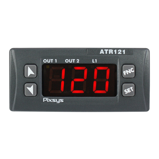
Display and keys functions Numeric indicators (Display) Normally displays the process. 1234 Meaning of status lights (Led) ON when command output is active. When 2 OUT1 it flashes, display shows the command output setpoint (which can be modified by arrow keys). ON when alarm output is active. -
Page 18: Keys
Keys • Allows to decrease main setpoint. • During configuration it allows to scroll ¶ through parameters and to modify them togheter with • If pressed after , it allows to decrease the setpoints (command with OUT1 flashing/ alarm with OUT2 flashing). •... -
Page 19: Controller Functions
Controller functions Modifying main setpoint and alarm setpoint values Setpoint value can be changed by keyboard as follows: Press Display § ¶ Increase or decrease Display shows the the main setpoint command setpoint value. Afer 4s display and OUT1 flashes. shows the process. -
Page 20: Manual Tuning
Manual tuning Manual procedure allows the user greater fl exibility to decide when to update PID algorithm parameters. It can be enabled § selecting Man on par. 27 Tuning launch: press , display shows , pressing t.of visualizes process value and (alternately) up to procedure ¶... -
Page 21: Latch On Function
• With the controller not connected to power supply: The memory card is equipped with an internal battery with an autonomy of about 1000 operations (button battery 2032, replaceable). Insert the memory card and press the programming button . When writing the parameters, the led turns red and on completing the procedure it turns green. - Page 22 For the calibration procedure refer to the following table: Press Display Exit parameters Place the sensor on confi guration. minimum operating Device visualizes value (associated with alternately process Lo. n ¶ Place the sensor on Set the value on maximum operating minimum.
-
Page 23: Dual Action Heating-Cooling
Dual action Heating-Cooling The ATR121/141 is suitable also for systems requiring a combined heating-cooling action. Command output must be configured as Heating PID (par.11 and par. 15 reG. greater than 0), and one of the alarm must be configured p.b. as cooling action (par. - Page 24 x = COOL x = COOL x = COOL < 0 < 0 < 0 (HEAT) (HEAT) (HEAT) COMMAND OUTPUT (HEAT) ACTIVE COMMAND OUTPUT (HEAT) ACTIVE COMMAND OUTPUT (HEAT) ACTIVE ALARM OUTPUT (COOL) ACTIVE...
-
Page 25: Dead Band Function
Cooling fluid type co.f P.b.m t.c.2 1.00 1.25 Water 2.50 Dead band function The dead band function (enabled selecting on par. 28 F.b.M ) creates a band within which the relays are both open or closed. In heating functioning (par. selected on ), the reG. -
Page 26: Configuration
Configuration 10.1 Loading default values This procedure allows to restore factory settings of the device. Press Display Display shows with the 1st digit for 3s flashing. § ¶ Change the flashing digit and move Enter password to the next one pressing Instrument loads default settings and... -
Page 27: Configuration Parameters
Press Display Enter the new data Increase or decrease which will be saved § ¶ the value displayed by on releasing the keys. pressing firstly To change another then an arrow key. parameter return to point 4. End of configuration parameter change. - Page 28 Sensor Analogue input configuration. For a correct functioning of the device, use sensors insulated from the ground. Otherwise, use a single transformer isolated for each instrument. 1 p. 40 Tc-K -260 °C..1360 °C (default) 1 p. 40 Tc-S -40 °C..1760 °C tc.s 1 p.
- Page 29 Upper Limit Setpoint Hi.s. -199..999 Value expressed as degrees.tenths for temperature 2 p. 40 sensors and digits for linear sensors and poten- tiometers (default: 999 for ATR121 and 1750 for ATR141). Lower Linear Input Lo. N Range AN1 lower limit only for linear signals. Example: with input 4..20 mA this parameter takes value associated to 4 mA -199..999...
- Page 30 Gain calibration cA.G Percentage value that is multiplied for the process value (allows to calibrated the working point) -19.9%..99.9%. Percentage (default 0.0) Regulation type ReG. Heating (N.A.) (Default) Cooling (N.C.) Absolute alarm with manual reset m.r. Absolute alarm with manual reset and relay m.r.m status stored in case of power failure.
- Page 31 Proportional band p.b. Proportional band Process inertia in units (in °C if temperature) 0..999 0 = On/Off Value degrees.tenths for temperature sensors and digit p. 40 for linear sensors and potentiometers (default 0) Integral time t. i . Process inertia in seconds 0..999 s (0 = integral disabled) (default 0) Derivative time t.d.
- Page 32 Alarm state output c.r.a Output contact and intervention type Normally open, active at start (default) n.o.s Normally closed, active at start n.c.s 3 p. 40 Normally open, active on reaching alarm n.o.r Normally closed, active on n.c.r 3 p. 40 reaching alarm Alarm state error s.c.a...
- Page 33 Conversion filter ADC Filter: Number of input sensor readings to calculate the mean that defines process value. NB: When means increase, control loop speed slows down 1..15 sample means 15Hz (default 10) Tune Autotuning type selection (par. 8.1) Disabled (default) Automatic.
- Page 34 Baud rate bd.r Selects baud rate for serial communication 300 bit/s mb. 1 9600 bit/s mb.2 19200 bit/s (default) mb.3 38400 bit/s mb. 4 Slave address Selects slave address for serial communication 1..254 (default 254) Serial delay de.s Selects serial delay 0..100 ms (default 20) Cooling fluid co.f...
- Page 35 Cooling cycle time t.c.2 Cycle time for cooling output 1..300 s (default 10) Visualization filter FL.u Slows down the refresh of display, to simplify reading Disabled (max. speed for display refresh) (default) First order filter on.f 2 Samples Mean s. 2 3 Samples Mean s.
-
Page 36: Alarm Intervention Modes
Alarm intervention modes 12.a Absolute alarm or threshold alarm ( selection) A. A Absolute alarm with Alarm Spv controller in heating Hysteresis parameter functioning (par. 11 reG. > 0 come ) and hysteresis (par. 23 ) in absolute HY.a Time value. - Page 37 12.c Band alarm ( selection) A. b Band alarm with hysteresis. N.B.: hysteresis (par. 23 ) can not be lower HY.a than 0. The alarm value is the upper or lower Hysteresis deviation from the parameter > 0 command setpoint that enables the output.
- Page 38 Upper deviation alarm Comand Spv Comand Spv Alarm Spv Alarm Spv Alarm Spv Alarm Spv value of alarm Hysteresis setpoint less than “0”. parameter > 0 N.B.: hysteresis (par. 23 ) can not be lower Time HY.a than 0. Alarm Off...
-
Page 39: Table Of Anomaly Signals
Table of anomaly signals If installation malfunctions, controller will switch off regulation output as selected on par. 12 s.c.c. s.c.a will report the anomaly. Example: controller will report failure of a connected thermocouple visualizing e-5 (flashing). For other signals, see table below. Cause Error in EEPROM cell Call Assistance... -
Page 40: File
Are you a mechanical designer looking for the 3D model files of the enclosure? Download them from Documentation Area. www.pixsys.net/prodotti/ regolatori-visualizzatori/ atr121-19-documentazione Notes / Updates 1. On ATR121 version the upper limit is 999 °C. 2. The display of decimal point depends on the setting of parameter sen. - Page 41 Table of configuration parameters Command output c.ou Sensor Decimal point d.p. Lower Limit Setpoint Lo.s Upper Limit Setpoint Hi.s. Lower Linear Input Lo. N Upper Linear Input Hi.n Latch On function Offset calibration cA.o Gain calibration cA.G Regulation type ReG. Command state error S.c.c.
- Page 42 Degree selection Baud rate bd.r Slave address Serial delay de.s Cooling fluid co.f Proportional band multiplayer p.b.m Overlap / dead band ou.d Cooling cycle time t.c.2 Visualization filter FL.u 42 - ATR121 - User manual...
- Page 43 Prima di utilizzare il dispositivo leggere con attenzione le informazioni di sicurezza e settaggio contenute in questo manuale. Proc. Cont. Eq. E469441 PIXSYS s.r.l. www.pixsys.net sales@pixsys.net - support@pixsys.net online assistance: http://forum.pixsys.net via Po, 16 I-30030 Mellaredo di Pianiga, VENEZIA (IT) Tel +39 041 5190518 2300.10.056-RevI...
Need help?
Do you have a question about the ATR 121 Series and is the answer not in the manual?
Questions and answers