Table of Contents
Advertisement
Quick Links
Advertisement
Table of Contents

Related Manuals for Pixsys ATR 142


Summary of Contents for Pixsys ATR 142
- Page 1 ATR 142 Controller User manual...
-
Page 3: Table Of Contents
Table of contents 1 Safety standards ................6 2 Model Identification ................. 6 3 Technical Data ................... 7 3.1 General Features ..............7 3.2 Hardware Features ..............7 3.3 Software Features ..............8 4 Dimensions and Installation ............8 5 Electrical wirings ................9 5.1 Wiring diagram ................ - Page 4 9.3 Dual sequential timer ............25 9.4 Dual timer loop ..............26 9.5 Relating timers to alarms ............26 10 Serial Communication ..............27 10.1 Slave ..................27 10.2 Master ..................32 10.2.1 Master mode in retransmission ......32 10.2.2 Master Mode Remote process .......34 11 Configuration ...................34 11.1 Modify Configuration Parameter ........34 12 Table of configuration parameters ..........35 13 Alarm Intervention Modes ............50...
-
Page 6: Safety Standards
Introduction Thank you for choosing a Pixsys controller. With the ATR142 model Pixsys makes available in a single device multiple options related to sensor input and actuators command in addition to the extended power range 24…230 Vac/Vdc. With 17 sensors to select and outputs configurable as relay or SSR command, the user or retailer can reduce stock by rationalising investment and device availability. -
Page 7: Technical Data
Technical Data General Features Display 4 0.40 inch displays + 4 0.30 displays Operating 1 relays 8A + 1 Ssr + RS485 temperature IP65 front panel (with gasket) Sealing IP30 box, IP20 terminals Material Polycarbonate UL94V2 self-extinguishing Weight 100 g Hardware Features AN1. -
Page 8: Software Features
28.5 x 70.5 mm Suggested thickness Spessore suggerito 2 ÷ 8 mm Guarnizione per 32x74 Cod. 1600.00.082 (optional) Gasket for 32x74 Memory Card (optional) Cod. MEMORY 2100.30.005 PIXSYS 42mm 42mm Memory Card (optional) inserimento insert with battery Memory Card Memory Card Cod. -
Page 9: Electrical Wirings
• Avoid proximity of remote control switches, electroma- gnetic contactors, powerful engines and in all instances use specific filters. • Avoid proximity of power groups, especially those with phase control Wiring diagram PIXSYS ATRxxx-xxT PIXSYS ATRxxx-xx 2 wire 4/20mA 2 wire... - Page 10 For thermoresistances PT100, NI100 Shield/Schermo • For the three-wire connection use wires with the same section • For the two-wire connection short- circuit terminals 10 and 12 • When shielded cable is used, it should be grounded at one side only WHITE For thermoresistances NTC, PTC, Shield/Schermo...
- Page 11 For signals 0/4..20mA with external 0/4...20mA power of sensor • Comply with polarity EXTERNAL SUPPLY C = Sensor output ALIMENTAZIONE ESTERNA B = Sensor ground PRESSURE TRANSMITTER SENSORE DI PRESSIONE For signals 0/4..20mA with two-wire 4...20mA sensor • Comply with polarity C = Sensor output A = Sensor power supply (12V/30mA) PRESSURE TRANSMITTER...
- Page 12 5.1.e Relay Q1 Output Capacity: • Q1: 8A, 250Vac,resistive loads,10 operations. 30/3A, 250Vac, cosφ=0.3, operations. • Q2: 5A, 250Vac, resistive loads, 105 operations. 20/2A, 250Vac, cosφ=0.3, operations. 5.1.f SSR output SSR command output 12V/30mA 5.1.g Digital Input Digital input according to parameter DGT.i.
-
Page 13: Configuration Easyup
To simplify the setting of parameters and the integration of the different components involved in the control system, Pixsys introduces the EASY-UP coding which allows to set sensors and/or command outputs in a single step. By means of the code listed in the data sheet enclosed to the sensor or actuator (SSR, motorized valve etc..) the... -
Page 14: Display And Keys Functions
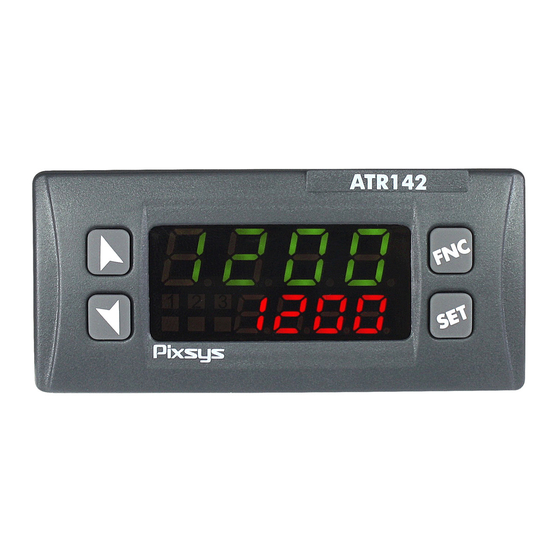
Display and keys functions ATR 142 Numeric indicators (Display) Normally displays the process. During the confi guration phase, it displays the parameter 1234 being inserted. Normally displays the setpoint. During the confi guration phase, it displays the parameter 1234 value being inserted. -
Page 15: Keys
Keys • Allows to decrease main setpoint. • During configuration phase, allows to slide through parameters. Together with key it “ m ” modifies them. • Pressed after key it allows to decrease alarm setpoint. • Allows to increase main setpoint. •... -
Page 16: Auto-Tune
Auto-Tune Tuning procedure calculates the controller parameters and can be manual or automatic according to selection on parameter 46 tune Manual tuning Manual procedure allows the user greater flexibility to decide when to update PID algorithm parameters. The procedure can be activated in two ways. •... -
Page 17: Automatic / Manual Regulation For % Output Control
Automatic/manual tuning cannot be enabled if the Soft start is active. Automatic / manual regulation for % output control This function allows to select automatic functioning or manual command of the output percentage. Parameter 49 Au.ma. , can select two methods. •... -
Page 18: Memory Card (Optional)
Maintenance time Cycle starts at each activation Mantenimento Setpoint 2 Cooling of the controller, or via Max Power Ra reddamento Max Potenza digital input if it is enabled Setpoint 1 Rising gradient for this type of functioning Gradiente di salita (parameter 50 dGt.i. -
Page 19: Loading Default Values
Loading default values This procedure allows to restore factory settings of the device Press Effect Display 1 shows 0000 with the 1st digit FNC for 3s. flashing, while display 2 shows pass Change the flashing digit and move to the “... -
Page 20: Digital Input Functions
For the calibration procedure refer to the following table: Press Eff ect Place the sensor on the Exit parameters minimum operating confi guration. Display 2 position (associated shows the writing Latc. with Lo.L.i. ) Place the sensor on the Set the value to maximum operating “... - Page 21 2t.s. : Switch two thresholds setpoint: with open contact ATR142 regulates on SET1; with closed contact regulates on SET2; 2t.s.i. : Switch two thresholds setpoint: setpoint selection is done by an impulse on digital input; 3t.s.i. : Switch three thresholds setpoint by an impulse on digital input;...
-
Page 22: Dual Action Heating-Cooling
8.12 Dual action heating-cooling ATR142 is suitable also for systems requiring a combined heating-cooling action. Main command output must be configured foe hearting PID ( act.t. = Heat and p.b. must be greater than 0), and one of the alarms ( AL. 1 or AL. 2 ) must be configured as cooL. Command output must be connected to the actuator responsible for heat, while the alarm output will control cooling action. - Page 23 x = COOL x = COOL x = COOL < 0 < 0 < 0 (HEAT) (HEAT) (HEAT) COMMAND OUTPUT (HEAT) ACTIVE COMMAND OUTPUT (HEAT) ACTIVE COMMAND OUTPUT (HEAT) ALARM OUTPUT (COOL) ACTIVE ACTIVE...
-
Page 24: Timer Operation
Timer operation Timer operation is enabled by parameter 63 tmr.f. To modify duration of counting time, follow the steps below: Press Effect Press until tim. 1 or tim. 2 visualized on display 1. Increase or decrease Digits on display 2 2 “ n ” and “ m ” time value for the changes. -
Page 25: Dual Sequential Timer
Press Effect FNC Press until tim. 1 or tim. 2 visualized on display 1. Back to point 1, after Start the Timer. Display selection of running 2 shows decrementing Timer time and Led “ n ” press “ n ” to stop switches on (fixed for timer 1, flashing for counting. -
Page 26: Dual Timer Loop
Dual timer loop This option enables 2 Timers and the time value is selectable by the operator. At elapsing of one Timer, the other one will automatically start and this sequence is repeated cycling. To achieve operation of dual timer loop set the parameter 63 tmr.f. -
Page 27: Serial Communication
Alarm active at elapsing of Timer2 until any key is pressed. Option not t.2.e.a. Timer 2 End Alarm available for Dual sequential Timer and Dual Timer Loop. t.2.w.e. Timer 2 Warning Alarm active for the last 5” of Timer2 Expiring t. - Page 28 At each parameter configuration, the device stores changed values in the EEPROM memory (100000 writing cycles), while setpoints are stored with a delay of 10 seconds after last modification. NB: modifications made to words different from those described in the following table can lead to instrument malfunction.
- Page 29 Loading default values: 9999 restore all values 9998 restore all values except for baud-rate and slave address 9997 restore all values except for slave address 9996 restore all values except for baud-rate Process (with tenths of degree for 1000 temperature sensors; digits for linear sensors) 1001 Setpoint1...
- Page 30 Error flags Bit0 = Eeprom writing error Bit1 = Eeprom reading error Bit2 = Cold junction error 1013 Bit3 = Process error (sensor) Bit4 = Generic error Bit5 = Hardware error Bit6 = Master off-line Bit7 = Missing calibration data Cold junction temperature 1014 (tenths of degree)
- Page 31 Visualized Alarm 2 (decimal as 1106 R/W EEPROM display) Setpoint gradient (decimal as 1107 EEPROM display) Heating output percentage 1108 (0-1000) Heating output percentage 1109 (0-100) Cooling output percentage 1110 (0-1000) Cooling output percentage 1111 (0-100) 2001 Parameter 1 R/W EEPROM 2064 Parameter 64 R/W EEPROM...
-
Page 32: Master
Word serial outputs Bit 0 = Q1 relay 3019 R/W 0 Bit 1 = Q2 relay Bit 2 = SSR Word serial outputs state if off-line Bit 0 = Q1 relay 3020 R/W 0 Bit 1 = Q2 relay Bit 2 = SSR 3021 Word serial process R/W 0... - Page 33 Description mast. w.pro. Write process value Write Process r.w.co. Write and read command setpoint Read/Write value Command Setpoint w.ou.p. Write output percentage rated by P.I.D. Write Output function (Range 0-10000) Percentage r.w.a. 1 Read/Write Alarm 1 Write and read alarm 1 setpoint value The read/written value might be rescaled according to the proportion described in the following table: Value limits input...
-
Page 34: Master Mode Remote Process
The input value (included between minimum and max limit) is linearly converted into the retransmitted value which is included between min and max output value. Rescaling is not executed if parameters Lo.L.r. and up.L.r. have the same value. 10.2.2 Master Mode Remote process To enable this function it is necessary to select r.pro. -
Page 35: Table Of Configuration Parameters
Display 1 shows the first parameter and confirm display 2 shows the value. Slide up/down 4 “ n ” and “ m ” through parameters Enter the new data Increase or decrease which will be saved the value displayed on releasing the by pressing firstly “... - Page 36 ATR142-ABC Command Alarm 1 Alarm 2 c.o1 c.o2 c.ssr Q1(opens) Q2(closes) c.uaL. ATR142-ABC-T Command Alarm 1 c.o1 c.ssr Q1(opens) SSR(closes) - c.uaL. Sensor SEN. analogue input configuration. Tc-K -260…1360°C > Default Tc. k Tc-S -40…1760°C Tc. s Tc-R -40…1760°C Tc. r Tc-J -200…1200°C Tc. J PT100 -200…600°C PT100 -200…140°C...
- Page 37 Decimal Point d.p. select number of displayed decimal points. > Default 1 Decimal 2 Decimals 0.00 3 Decimals 0.000 Lower Limit Setpoint Lo.L.s. lower limit setpoint. -999…+9999 [digit ] (degrees.tenths for temperature sensors) Default: 0. Upper Limit Setpoint UP.L.S. upper limit setpoint. -999…+9999 [digit ] (degrees.tenths for temperature sensors) Default: 1750.
- Page 38 Offset Calibration o.caL. number added/subtracted to process value visualized on display (usually correcting the ambient temperature value). -999…+1000 [digit ] for linear sensors and potentiome- ters. -99.9…+100.0 (degrees.tenths for temperature sensors). > Default: 0.0. Gain Calibration G.caL. this % is multiplied with displayed value to calibrate the process value.
- Page 39 Command Hysteresis c. HY. hysteresis in ON/OFF or dead band in P.I.D. -999…+999 [digit ], (degrees.tenths for temperature sensors) > Default: 0.0 Command Delay c. de. (only in ON/OFF functioning).(In case of servo valve it also functions in PID and represents the delay between the opening and closure of the two contacts).
- Page 40 Cycle Time t.c. Cycle time for time-proportioning output (10/15sec for PID contactors, 1 sec for PID on SSR or value declared by manufacturer for motorised valves) 0.1-300.0 sec. > Default: 10.0. For motorised valve min. time is 1.0 sec Output Power Limit o.po.L.
- Page 41 Alarm 1 State Output a. 1 .s.o. alarm 1 output contact and intervention type (n.o. start) Normally open, active at start > n.o. s. Default (n.c. start) Normally closed, active at start. n.c. s. (n.o. threshold) Normally open, active on n.o. t. reaching alarm (n.c.
- Page 42 Alarm 1 Delay a. 1 .de. -180…+180 Sec. > Default: 0. Negative: delay at exit from alarm Positive: delay at starting of alarm Alarm 1 Setpoint Protection a. 1 .s.p. does not allow the user to modify setpoint. > Default Free Locked Lock.
- Page 43 Alarm 2 State Output a.2.s.o. alarm 2 output contact and intervention type. (n.o. start) Normally open, active at start. > n.o. s. Default (n.c. start) Normally closed, active at start. n.c. s. (n.o. threshold) Normally open, active on n.o. t. reaching alarm (n.c. threshold) Normally closed, active on n.c. t.
- Page 44 Alarm 2 Setpoint Protection a.2.s.p. Alarm 2 set protection. Does not allow operator to change setpoint value. > Default free Locked Lock. Locked and hidden Hide Cooling Fluid coo.f. select type of cooling fluid for Heating/Cooling PID (parameter 7.12) Air > Default Water Proportional Band Multiplier p.b.m.
- Page 45 9 Samples Mean 9. s.m. 10 Samples Mean > Default 10.s.m. 11 Samples Mean 11.s.m. 12 Samples Mean 12.s.m. 13 Samples Mean 13.s.m. 14 Samples Mean 14.s.m. 15 Samples Mean 15.s.m. Conversion Frequency c.frn. Frequency of sampling for analogue-digital converter. 242 Hz Max ADC conversion frequency 242H.
- Page 46 7 Samples Mean 7. s.m. 8 Samples Mean 8. s.m. 9 Samples Mean 9. s.m. 10 Samples Mean 10.s.m. Tune tune tuning type selection Disabled > Default dis. Automatic. PID parameters are calculated at auto each activation and/or change of setpoint. Manual. Launch by keyboard or by digital input. man.
- Page 47 Digital Input dGt.i. Digital input functioning. (parameter 7.11) Parameter 48 selection must be cont. or Pr.cy. Disabled > Default dis. Start/Stop st.st. Run n.o. rn.n.o. Run n.c. rn.n.c. L.c.n.o. Lock Conversion n.o. (Lock visualisation on display with N.O. contact) Lock Conversion n.c. (Lock visualisation on L.c.n.c.
- Page 48 User Menu Cycle Programmed u.m.c.p. Allows the rising/falling gradient and the maintenance time to be changed from the user menu in pre-program- med cycle functioning. (parameter 7.7) Disabled > Default dis. Rising Gradient (modify gradient) r i.Gr. Maintenance Time (modify time) ma.t.i.
- Page 49 Slave Address sL.ad. select slave address for serial communication 0 – 255 > Default: 254. Serial Delay se.de. select serial delay 0 – 100 milliseconds > Default: 20. Master mast. select master mode. (parameter 9.2) Disable > Default dis. Write Process w.pro Read Write Command Setpoint r.w.co.
-
Page 50: Alarm Intervention Modes
Timer Function tmr.f. enable 1 or 2 Timers which may be set from user menu and which can be related to alarms. (parameter 8) Disable > Default dis. Single Timer Seconds s.tm.s. Double Timer Seconds d.tm.s. d.s.t.s. Double Sequential Timer Seconds Double Timer Loop Seconds d.t.L.s. - Page 51 Hysteresis parameter Absolute alarm with < 0 controller heating Alarm Spv. functioning (Parameter 11 act.t. selected Heat ) and hysteresis value less than Time “0” (Parameter 28 a. 1 .Hy. < 0). * Alarm output Time Absolute alarm with controller cooling Hysteresis...
- Page 52 13.b Absolute alarm or threshold alarm referring to setpoint command ( selection) a.c.aL. Absolute alarm refers to the command set, with the controller in heating Command Spv functioning (Parameter 11 Hysteresis parameter act.t. selected Heat ) and > 0 hysteresis value greater Alarm Spv than “0”...
- Page 53 13.d Upper Deviation Alarm ( selection) H.d.aL. Alarm Spv Upper deviation alarm Hysteresis value of alarm setpoint parameter > 0 greater than “0” Command Spv hysteresis value greater than “0” (Parameter 28 Time a. 1 .Hy. > 0). ** Alarm output Upper deviation alarm Command Spv...
-
Page 54: Table Of Anomaly Signals
Hysteresis parameter > 0 Lower deviation alarm Alarm Spv value of alarm setpoint less than “0” and Command Spv hysteresis value greater than “0” (Parameter 28 Time a. 1 .Hy. > 0). ** Alarm output * The example refers to alarm 1; the function can also be enabled for alarm 2 on model that include it. - Page 55 Check the serial Off-line in master mode E-06 connection, baud-rate remote process ser.e. and device ID. E-08 Missing calibration data Call Assistance sYs.e. Notes User manual - ATR142- 55...
- Page 56 Table of configuration parameters Command Output c.out Sensor SEN. Decimal Point d.p. Lower Limit Setpoint Lo.L.s. Upper Limit Setpoint UP.L.S. Lower Linear Input Lo.L.i. Upper Linear Input up.L.i. Latch On Function Latc. Offset Calibration o.caL. Gain Calibration G.caL. Action type act.t.
- Page 57 Alarm 2 Reset a.2.re. Alarm 2 State Error a.2.s.e. Alarm 2 Led a.2.Ld. Alarm 2 Hysteresis a.2.HY. Alarm 2 Delay a.2.de. Alarm 2 Setpoint Protection a.2.s.p. Cooling Fluid coo.f. Proportional Band Multiplier p.b.m. Overlap/Dead Band ov.d.b. Cooling Cycle Time co.t.c. Conversion Filter c.fLt.
- Page 58 Prima di utilizzare il dispositivo leggere con attenzione le informazioni di sicurezza e settaggio contenute in questo manuale. PIXSYS s.r.l. www.pixsys.net sales@pixsys.net - support@pixsys.net online assistance: http://forum.pixsys.net 2300.10.092-RevL Software Rev. 1.21 110117...
Need help?
Do you have a question about the ATR 142 and is the answer not in the manual?
Questions and answers
Не получается настроить чтобы выключался при определенной температуре