Table of Contents
Advertisement
Available languages
Available languages
Advertisement
Table of Contents

Related Manuals for Pixsys ATR 171


Summary of Contents for Pixsys ATR 171
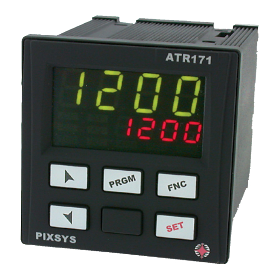
- Page 1 ATR 171 Controller / Regolatore User manual / Manuale d’uso...
-
Page 3: Table Of Contents
Table of contents 1 Safety standards ............................5 2 Identification of the model .........................5 3 Technical data ............................5 3.1 Genera l features ..........................5 3.2 Hardware features........................6 3.3 Software features ........................6 4 Dimension and installation ........................7 5 Electrical connections ..........................7 5.1 Connection diagram ........................8 6 Display and keys functions .......................14 6.1 Numeric indicators (Display) ....................14 6.2 Meaning of Status Lights (Led)....................14... - Page 4 Indice degli argomenti 1 Norme di sicurezza ..........................47 2 Identificazione di modello ........................47 3 Dati tecnici ............................47 3.1 Caratteristiche generali ......................47 3.2 Caratteristiche Hardware ......................48 3.3 Caratteristiche software ......................48 4 Dimension and installation ......................49 5 Collegamenti elettrici.........................49 5.1 Schema di collegamento ......................50 6 Funzione dei visualizzatori e tasti ....................56 6.1 Indicatori numerici (Display) ....................56 6.2 Significato delle spie di stato (Led) ..................56...
-
Page 5: Safety Standards
Introduction Thank you for having chosen a Pixsys instrument. With ATR171 model, Pixsys integrates in a single device all options for sensors reading and actuators control, beside an useful supply with extended range 24..230 Vac/Vdc. Thanks to 17 selectable probes and outputs configurable as relay or SSR, the user or the retailer can reduce stock needs. -
Page 6: Hardware Features
3.2 Hardware features AI1 - AI2: Configurable via software. Tolerance (25 °C) Input: +/-0.2% ±1 digit for thermo- Thermocouple type K, S, R, J. couple, thermoresistance and Automatic compensation of V / mA. cold junction from 0..50 °C. Cold junction accuracy 0.1 °C/°C. Analogue Thermoresistances: PT100, imput... -
Page 7: Dimension And Installation
Dimension and installation Memory Card (optional) Cod. MEMORY C241 Memory Card (optional) 42mm with battery Cod. MEMORY C243 insert / inserimento Memory Card 72 mm ATR171 ATR171-23ABC-T SUPPLY SSR/V 24...230V AC/DC +Vdc 230V 1/2HP 485- 485+ 230V 1/2HP 230V 1/2HP Memory Card Spessore suggerito Suggested thickness DIMA DI FORATURA... -
Page 8: Connection Diagram
5.1 Connection diagram ATR171-11ABC ATR171-12ABC ATR171-23ABC-T ATR171-14ABC 8 ATR171 - User manual... - Page 9 5.1.a Power supply SUPPLY Switching supply with exstended range 24..230 Vac/dc 24...230V ±15% 50/60 Hz – 5,5 VA. AC/DC 5.1.b Analogue input AI1 For thermocouples K, S, R, J. Shield/Schermo • Comply with polarity. • For extensions make sure to use the correct extension/ compensating cable.
- Page 10 5.1.c Analogue input AI2 (only for ATR171-23ABC-T) To enable the second analogue input, set the dip switches as indicated in the figure. In this configuration the serial RS485 is not available. For thermocouples K, S, R, J. • Comply with polarity. Shield/Schermo •...
- Page 11 4...20mA For linear signals 0/4..20 mA with three-wires sensors. Comply with polarity: A= Sensor supply B= Sensor ground C= Sensor output PRESSURE TRANSMITTER / SENSORE DI PRESSIONE 18 C For linear signals 0/4..20 mA with external power supply 4...20mA for sensor. Comply with polarity: External supply / C= Sensor output...
- Page 12 5.1.e Relay outputs Q1, Q2, Q3 Contacts capacity: 8 A, 250 Vac, resistive charge 10 operations; 30/3 A, 250 Vac, cosφ= 0.3, 10 operations. 230V 230V 1/2HP 1/2HP 230V 1/2HP 5.1.f Relay output Q4 (only for ATR171-14ABC) Contacts capacity: 5 A, 30 Vac/dc, resistive 18x10 operations.
- Page 13 5.1.g SSR output SSR Command output 12 V / 30 mA. To use SSR output it is necessary to set channel 1 of DIP2 as indicated in the figure. 5.1.h Output mA / Volt (only for ATR171-23ABC-T) Analogue output in mA configurable as command (Par. c.out ) or retransmission of process-setpoint (Par.
-
Page 14: Display And Keys Functions
Display and keys functions ATR171 6.1 Numeric indicators (Display) Normally displays the process. During the configuration phase, it 1234 displays the parameter being inserted. Normally displays the setpoint. During the configuration phase, it 1234 displays the parameter value being inserted. 6.2 Meaning of Status Lights (Led) On when command output is active. -
Page 15: Keys
6.3 Keys • Increases main setpoint. • In configuration mode allows to scroll and modify parameters. • Press after key increases alarm setpoints or time value of timer. • Decreases main setpoint. • In configuration mode allows to scroll and modify parameters. ... -
Page 16: Selection Of Process Value Related To The Command Output And To The Alarms
7.1 Selection of process value related to the command output and to the alarms When second input is enabled (par. 9 Sen.2 other than dis. ) it is possible to choose the process value to be related to command output, to alarms and to retransmission. Following options are available: •... -
Page 17: Controller Functions
Controller functions 8.1 Modification of main and alarm setpoint value Setpoint value can be modified from keyboard as follows: Increase or decrease main Value on display 2 changes setpoint value Visualizes alarm setpoint on display Increase or decrease alarm Value on display 2 changes ... -
Page 18: Soft-Start
• In case of power failure or after a switch-off , at restart both the manual functioning and the previously fi xed output percentage value will be maintained. • If during automatic functioning there is a sensor failure, controller will automatically switch to manual mode while maintaining command output percentage unchanged as generated by P.I.D. -
Page 19: Memory Card (Optional)
8.8 Memory Card (optional) Parameters and setpoint values can be easily copied from one controller to others using the Memory Card. Two modes are available: 1 With the controller connected to the power supply. Insert Memory card when the controller is off. At switch-on display 1 visualizes memo and display 2 visualizes ... -
Page 20: Timer Function
Press Display To exit standard proceeding press Store value on max. FNC. For “virtual zero” setting, Display shows HiGh . place the sensor to zero point. Set the virtual zero. Display shows uirt. . N.B.: If u.0in. is selected, To exit procedure press FNC. -
Page 21: Digital Input Functions (Only For Atr171-11/12/14Abc)
• tmr.i. : start / stop of Timer function (See par. 8.10); The parameter 70 op.mo. , enable other functions to use digital imput: • pr.cy. : Pre-programmed cycle (See par. 8.7); • 2t.s. , 2t.s.i , 3t.s.i , 4t.s.i : It’s possible to use digital input for setpoint change function. - Page 22 x = COOL x = COOL x = COOL < 0 < 0 < 0 (HEAT) (HEAT) (HEAT) ACTIVE COMMAND OUTPUT (HEAT) ACTIVE COMMAND OUTPUT (HEAT) ACTIVE ACTIVE ALARM OUTPUT (COOL) COMMAND OUTPUT (HEAT) ACTIVE...
-
Page 23: Serial Communication (Only For Atr171-23Abc-T)
Serial communication (only for ATR171-23ABC-T) To enable serial input set the dip switchs as indicated in the figure: In this configuration mode, parameters and functioning related to double analogue input are not available. 9.1 Modbus RTU ATR171-23ABC-T is provided with RS485 and can receive/broadcast data via MODBUS-RTU protocol. - Page 24 Read Reset Modbus Description Write value address Device type EEPROM Sotware version EEPROM Slave address EEPROM Boot version EEPROM Automatic addressing Installation code comparison Loading Default values: 9999 restore all values 9998 restore all values except for baud-rate and slave address 9997 restore all values except for baud-rate 9996 restore all values except for slave address Process (degrees with tenths of degree for...
- Page 25 Read Reset Modbus Description Write value address Bit 4 = Error AI2 (probe 2) Bit 5 = Generic error Bit6 = Hardware error Bit 7 = Missing calibration error 1024 Bit 8 = Incongruous control parameters Bit 9 = Incongruous alarm parameters Bit 10 = Incongruous retransmission par.
-
Page 26: Configuration
Configuration 10.1 Modify configuration parameters For configuration parameters see next paragraph. Press Display Display 1 shows 0.000 with 1st PRGM digit flashing, while display 2 for 3s. shows Pass . Modify flashing digit and move to Enter password: 1234 . ... -
Page 27: Table Of Configuration Parameters
Table of configuration parameters The following table includes all parameters. Some of them will not appear on the models which are not provided with relevant hardware data. Command Output c.out Command output type selection Default c. o1 Command of open-loop valves c.uaL SSR command (voltage) c.ssr... - Page 28 Sensor 1 sen. 1 Analogue input configuration / sensor selection (AI1). Disabled (Default) dis. Tc-K -260..1360 °C tc. k Tc-S -40..1760 °C tc. s Tc-R -40..1760 °C tc. r Tc-J -200..1200 °C tc. J PT100 -200..600 °C PT100 -200..140 °C pt 1 NI100 -60..180 °C...
- Page 29 Gain Calibration 1 G.ca. 1 AI1 gain calibration. % value multiplied with displayed value to calibrate process value. -99.9%..+100.0%, Default: 1000 Example: to correct a scale 0...1000°C which is showing 0...1010°C, enter -1.0 on this parameter Latch-On Ltc. 1 Automatic setting of limits for linear input. Disabled.
- Page 30 Lower Limit Setpoint Lo.L.s. AI lower limit selectable for setpoint. (degrees if temperature), Default: 0. -999..+9999 digit Upper Limit Setpoint 2 up.L.s. AI2 upper limit setpoint. (degrees i f temperature), Default: 1750. -999..+9999 digit Command Process c.pro. Selects process value related to command output and visualized on display 1. This determinates which is the primary process Process 1 (Default) pro.
- Page 31 Command State Error c. se. Contact state for command output in case of error Open contact (Default) c.o. Closed contact c.c. Command Led c. Ld. Defines led OUT1 state corresponding to relevant contact ON with open contact c.o. ON with closed contact (Default) c.c.
- Page 32 Integral Time t.i. Process inertia in seconds 0.0..999.9 seconds. 0 integral disabled, Default: 0 Derivative Time t.d. Normally ¼ of integral time. 0.0..999.9 seconds. 0 derivative disabled, Default: 0 Cycle Time t.c. Cycle time (for P.I.D. on remote control switch 10 / 15 sec., for P.I.D. on SSR 1 sec.) or servo time (value declared by servo-motor manufacturer).
- Page 33 Alarm 1 Process a. 1 .pr. Select value correlated to alarm 1 Process 1 (Default) pro. 1 Process 2 pro.2 Processes mean Mean Processes difference diff. abs.d . Processes difference as absolute value Alarm 1 State Output a. 1 .s.o. Alarm 1 output contact and type of action n.o.
- Page 34 Alarm 1 Setpoint Protection a. 1 .s.p. Alarm 1 set protection. Does not allow the user to change setpoint Modification allowed (Default) free Protected Lock Protected and not visualized Hide Alarm 2 aL. 2 Alarm 2 selection. Alarm intervention is associated to AL2 (See par.
- Page 35 Alarm 2 Rearmament a.2.re. Type of reset for alarm 2 contact Automatic Reset (Default) a.re. Manual Reset by keyboard m.re. m.re.s. Manual reset stored (keeps relay status also after an eventual power failure) Alarm 2 State Error a.2.s.e. Contact status for alarm 2 output in case of error Open contact (Default) c.o.
- Page 36 Alarm 3 Process a.3.pr. Selects value correlated to alarm 3 Process 1 (Default) pro. 1 Process 2 pro.2 Processes mean mean Processes difference diff. Processes difference as absolute value abs.d. Alarm 3 State Output a.3.s.o. Alarm 3 output contact and type of action n.o.
- Page 37 Alarm 3 Setpoint Protection a.3.s.p. Alarm 3 set protection. Does not allow the user to change set value Modification allowed (Default) free Protected Lock Protected and not visualized Hide Timer functions tmrf Enabling timer function and select time base (See par. 8.10) (Default) dis.
- Page 38 5 Samples Mean 5. s.m. 6 Samples Mean 6. s.m. 7 Samples Mean 7. s.m. 8 Samples Mean 8. s.m. 9 Samples Mean 9. s.m. 10.s.m. 10 Samples Mean (Default) 11 Samples Mean 11.s.m. 12 Samples Mean 12.s.m. 13.s.m. 13 Samples Mean 14.s.m.
- Page 39 Operating mode op.mo. Selects operating mode. In model ATR171-23ABC-T, this parameter is visible only if dip-switches are configured for serial communication (AI2 desabled). Controller (Default) cont. Programmed Cycle pr.cy. 2 Setpoints Switch 2t.s. 2 Setpoints Switch Impulsive 2t.s.i. 3 Setpoints Switch Impulsive 3t.s.i.
- Page 40 Falling Gradient faGr Falling gradient for pre-programmed cyle. In model ATR171-23ABC-T, this parameter is visible only if dip-switches are configured for serial communication (AI2 desabled). 0 Disabled. 1..9999 Digit/hour (degrees/hour with decimal visualization if temperature), Default: 0. Maintenance Time ma.ti. Holding time for pre-programmed cycle.
- Page 41 Retransmission retr. Retransmission for output 0..10 V or 0/4..20 mA. Parameters 81 and 82 defines upper/lower limit of scale Disabled (Default) dis. Command Setpoint c.spu. Process 1 pro. 1 Process 2 pro.2 Processes Mean mean Processes Difference diff. Processes Difference as absolute value abs.d.
-
Page 42: Alarm Intervention Modes
Alarm Intervention Modes 12.a Absolute alarm (“Absolute” selection) ( selection) a. aL. Absolute alarm with controller in heating functioning (par. 17 act.t. selected Heat ) and hysteresis value greater than “0” (par. 36 a. 1 .Hy. > 0). * Absolute alarm with controller in heating functioning (par. - Page 43 12.b Absolute Alarm or Threshold Alarm Referring to Setpoint Command (selection a.c.AL. Absolute alarm refers to the command set, with the controller in heating functioning (par. 17 act.t. selected Heat ) hysteresis value greater than “0 (par. 36 a. 1 .Hy. > 0). Command set can be changed by pressing the arrow keys on front panel.
- Page 44 12.d Upper Deviation Alarm (selection H.d.aL. Upper deviation alarm value of alarm setpoint greater than “0” and hysteresis value greater than“0” (par. 36 a. 1 .Hy. > 0). ** Upper deviation alarm value of alarm setpoint minor than “0” and hysteresis value greater than “0”...
- Page 45 Table of Anomaly Signals If installation malfunctions, controller will switch off regulation output and will report the anomaly. For example, controller will report failure of a connected thermocouple visualizing e-05 (flashing) flashing on display. For other signals see table below. Cause What to do E-0 1...
- Page 46 Table of configuration parameters Command Output c.out Sensor 1 sen. 1 Decimal Point 1 d.p. Lower Linear Input 1 LOL.i Upper Limit Input 1 upL.i Offset Calibration 1 o.ca. 1 Gain Calibration 1 G.ca. 1 Latch-On Ltc. 1 Sensor 2 sen.2 Decimal Point 2 d.p.
- Page 47 Alarm 2 aL. 2 Alarm 2 Process a.2.pr. Alarm 2 State Output a.2.s.o. Alarm 2 Hysteresis a.2.Hy. Alarm 2 Rearmament a.2.re. Alarm 2 State Error a.2.s.e. Alarm 2 Led a.2.Ld. . Alarm 2 Delay a.2.de Alarm 2 Setpoint Protection a.2.s.p. Alarm 3 aL.
-
Page 48: Norme Di Sicurezza
Introduzione Grazie per aver scelto un regolatore Pixsys. Con il modello ATR171 Pixsys rende disponibile in un singolo strumento tutte le opzioni relative alla connessione dei sensori e al comando di attuatori, con in aggiunta un’utile alimentazione a range esteso da 24..230 Vac/Vdc. Con le 17 sonde selezionabili e l’uscita configurabile come relè... -
Page 49: Caratteristiche Hardware
3.2 Caratteristiche Hardware 1: AN1-AN2 Configurabile via software. Tolleranza (25 °C) Ingresso: +/-0.2% ±1 digit per ingresso Termocoppie tipo K, S, R, J. termocoppia, termoresistenza e V / mA. Compensazione automatica del giunto freddo da 0..50 °C. Precisione giunto freddo 0.1 Ingressi analogici Termoresistenze: PT100, °C/°C. -
Page 50: Dimension And Installation
Dimension and installation Memory Card (optional) Cod. MEMORY C241 Memory Card (optional) 42mm with battery Cod. MEMORY C243 insert / inserimento Memory Card 72 mm ATR171 ATR171-23ABC-T SUPPLY SSR/V 24...230V AC/DC +Vdc 230V 1/2HP 485- 485+ 230V 1/2HP 230V 1/2HP Memory Card Spessore suggerito Suggested thickness DIMA DI FORATURA... -
Page 51: Schema Di Collegamento
5.1 Schema di collegamento ATR171-11ABC ATR171-12ABC ATR171-23ABC-T ATR171-14ABC Manuale d’uso - ATR171 51... - Page 52 5.1.a Alimentazione SUPPLY Alimentazione switching a range esteso 24..230 Vac/dc 24...230V ±15% 50/60 Hz – 5,5 VA (con isolamento galvanico). AC/DC 5.1.b Ingresso analogico AI1 Per termocoppie K, S, R, J. Shield/Schermo • Rispettare la polarità. • Per eventuali prolunghe utilizzare cavo compensato e morsetti adatti alla termocoppia utilizzata (compensati).
- Page 53 Per termocoppie K, S, R, J. • Rispettare la polarità. Shield/Schermo • Per eventuali prolunghe utilizzare cavo compensato e morsetti adatti alla termocoppia utilizzata (compensati). • Quando si usa cavo schermato, lo schermo deve essere collegato a terra ad una sola estremità. Per termoresistenze PT100, NI100.
- Page 54 Per segnali normalizzati in corrente 0/4..20 mA con sensore a due fili. 4...20mA Rispettare le polarità: C= Uscita sensore PRESSURE TRANSMITTER / A= Alimentazione sensore SENSORE DI PRESSIONE 5.1.e Ingresso Seriale (solo per ATR171-23ABC-T) Per abilitare la seriale RS485 impostare i dip switch come in figura.
- Page 55 5.1.g Uscita Relè Q4 (solo per ATR171-14ABC) Portata contatti: 5 A, 30 Vac/dc, carico resistivo 18x10 operazioni. 1/8HP 5.1.h Uscita SSR Uscita comando SSR portata 12 V / 30 mA. Solo per la versione ATR171-23ABC-T, per utilizzare l’uscita SSR impostare il canale 1 del DIP 2 come in figura.
-
Page 56: Funzione Dei Visualizzatori E Tasti
5.1.j Ingresso digitale (solo per ATR171-11/12/14-ABC) +Vdc Ingresso digitale (Par. dGt.i. ). Funzione dei visualizzatori e tasti ATR171 6.1 Indicatori numerici (Display) Normalmente visualizza il processo. 1234 In fase di configurazione visualizza il parametro in inserimento. Normalmente visualizza i setpoint. In fase di configurazione 1234 visualizza il valore del parametro in inserimento. -
Page 57: Tasti
6.3 Tasti • Incrementa il setpoint principale. • In fase di configurazione consente di scorrere e modificare i parametri. • Premuto dopo il tasto SET incrementa i setpoint di allarme o il tempo per la funzione timer. • Decrementa il setpoint principale. •... -
Page 58: Selezione Grandezza Correlata Al Comando E Agli Allarmi
7.1 Selezione grandezza correlata al comando e agli allarmi Quando è abilitato il secondo ingresso (par. 9 sen.2 diverso da dis. ) è possibile decidere la grandezza da correlare al comando, agli allarmi e anche alla ritrasmissione. Le grandezze disponibili sono le seguenti: •... -
Page 59: Funzioni Del Regolatore
Funzioni del regolatore 8.1 Modifica valore setpoint principale e setpoint di allarme Tasto Effetto Eseguire Incrementare o diminuire il valore La cifra sul display 2 varia. del setpoint principale. Visualizza setpoint di allarme sul display 1. Incrementare o diminuire il valore La cifra sul display 2 varia. -
Page 60: Soft-Start
2 La seconda selezione ( en.st. ) abilita lo stesso funzionamento, ma con due importanti varianti: • Nel caso di temporanea mancanza di tensione o comunque dopo uno spegnimento, accendendo il regolatore, verrà mantenuto sia il funzionamento in manuale, sia il valore di percentuale dell’uscita precedentemente impostato. •... -
Page 61: Memory Card (Opzionale)
8.8 Memory Card (opzionale) È possibile duplicare parametri e setpoint da un regolatore ad un altro mediante l’uso della Memory Card. Sono previste due modalità: • con regolatore connesso all’alimentazione: inserire la Memory Card con regolatore spento. All’accensione il display 1 visualizza memo e il display 2 visualizza ---- (solo se nella Memory sono salvati valori corretti). -
Page 62: Funzione Timer
Tasto Eff etto Eseguire Posizionare il sensore sul valore Fissa il valore sul minimo. massimo di funzionamento Il display visualizza Lo. (associato a up.L.i. ). Per uscire dalla procedura standard tenere premuto FNC. Nel caso di Fissa il valore sul massimo. ... -
Page 63: Funzioni Da Ingresso Digitale (Solo Per Atr171-11/12/14Abc)
8.11 Funzioni da Ingresso digitale (solo per ATR171- 11/12/14ABC) L’utilizzo dell’ingresso digitale abilita alcune funzioni utili a semplificare l’operatività del regolatore. Selezionare la funzione desiderata sul parametro 72 dGt.i. (il parametro 70 op.mo. , deve essere impostato su Cont. ). •... - Page 64 dell’azione refrigerante secondo la formula: Banda proporzionale azione refrigerante = p.b. x p.b.m. Si avrà così una banda proporzionale per l’azione refrigerante che sarà uguale a quella dell’azione caldo se p.b.m. = 1.00, o 5 volte più grande se p.b.m. = 5.00. Tempo integrale e Tempo derivativo sono gli stessi per entrambe le azioni.
-
Page 65: Comunicazione Seriale (Solo Per Atr171-23Abc-T)
Tipo di fluido coo.f. p.b.m. co.c.t. refrigerante Aria 1.00 Olio 1.25 Acqua 2.50 Una volta selezionato il parametro coo.f. , i parametri p.b.m. , ou.d.b e co.T.c. possono essere comunque modificati. Comunicazione Seriale (solo per ATR171-23ABC-T) Per abilitare l’ingresso seriale impostare i dip switch come in figura: In questa configurazione i parametri e le funzionalità... - Page 66 Caratteristiche protocollo Modbus RTU Selezionabile da parametro 92 bd.rt. 4.8 k 4800 bit/sec 9.6 k 9600bit/sec Baud-rate 19.2k 19200bit/sec 28.8k 28800bit/sec 38. 4 k 38400bit/sec 57.6k 57600bit/sec Formato 8, N, 1 (8 bit, no parità, 1 stop) WORD READING (max 20 word) (0x03, 0x04) Funzioni SINGLE WORD WRITING (0x06) supportate...
- Page 67 Read Reset Modbus Description Write value address Stato allarmi (0 = Assente, 1 = Presente) Bit 0 = Allarme 1 1012 Bit 1 = Allarme 2 Bit 2 = Allarme 3 Riarmo manuale: scrivere 0 per riarmare tutti gli allarmi. In lettura (0 = Non riarmabile, 1 = Riarmabile): 1013 Bit 0 = Allarme 1...
-
Page 68: Configurazione
Read Reset Modbus Description Write value address 1104 Setpoint 4 con selezione del punto decimale EEPROM 1105 Allarme 1 con selezione del punto decimale EEPROM 1106 Allarme 2 con selezione del punto decimale EEPROM 1107 Allarme 3 con selezione del punto decimale EEPROM Setpoint reale (gradiente) con sel. -
Page 69: Caricamento Valori Di Default
Tasto Effetto Eseguire Si incrementa o decrementa il Inserire il nuovo dato che verrà valore visualizzato. salvato al rilascio dei tasti. Conferma l’inserimento del Per variare un altro parametro 8 SET dato (il display 2 smette di tornare al punto 4. lampeggiare). - Page 70 ATR171-12ABC Comando Allarme 1 Allarme 2 c. o1 Q1 (apri) - Q2 (chiudi) c.uaL. c.ssr ATR171-14ABC Comando Allarme 1 Allarme 2 Allarme 3 c. o1 Q1 (apri) - Q2 (chiudi) c.uaL. ATR171-23ABC Comando Allarme 1 Allarme 2 Allarme 3 c. o1 Q1 (apri) - Q2 (chiudi) c.uaL.
- Page 71 Decimal Point 1 d.p. Seleziona il tipo di decimale visualizzato per l’ingresso analogico 1. Default 1 decimale 2 decimali 0.00 3 decimali 0.000 Lower Linear Input 1 L.L.i. 1 Limite inferiore range AI1 solo per normalizzati. Es.: con ingresso 4...20 mA questo parametro assume il valore associato a 4 mA.
- Page 72 Sensor 2 sen.2 Configurazione ingresso analogico 2 (AI2). NB: impostare Dip-switch come indicato nel paragrafo 5.1.c. Disabilitato (Default) dis. Tc-K -260..1360 °C tc. k Tc-S -40..1760 °C tc. s Tc-R -40..1760 °C tc. r Tc-J -200..1200 °C tc. J PT100 -200..600 °C PT100 -200..140 °C...
- Page 73 Command Process c.pro. Seleziona la grandezza correlata all’uscita di comando e visualizzata sul display 1. Determina il processo primario. Processo 1 (Default) pro. 1 Processo 2 pro.2 Media processi Mean Differenza processi diff. Differenza in valore assoluto processi abs.d. Remote Setpoint rem.s.
- Page 74 Command Delay c. de. Ritardo comando (solo in funzionamento ON / OFF). In caso di servo valvola funziona anche in P.I.D. e rappresenta il ritardo tra l’apertura e la chiusura dei due contatti -600..+600 secondi (decimi di secondo in caso di servo valvola). Negativo: ritardo in fase di spegnimento.
- Page 75 Cycle Time t.c. Tempo ciclo (per P.I.D. su teleruttore 10” / 15”, per P.I.D. su SSR 1”) o tempo servo (valore dichiarato da produttore del servomotore) 0.1..300.0 secondi, Default: 10 Lower Limit Output Percentage L.L.o.p. Seleziona il valore minimo per la percentuale dell’uscita di comando 2 e tipo intervento 0..100%, Default: 0%.
- Page 76 Alarm 1 State Output a. 1 .s.o. Contatto uscita allarme 1 e tipo intervento n.o. s. (N.O. Start) Normalmente aperto, operativo dallo start (Default) (N.C. Start) Normalmente chiuso, operativo dallo start n.c. s. (N.O. Threshold) Normalmente aperto, operativo al raggiungimento n.o.
- Page 77 Alarm 1 Setpoint Protection a. 1 .s.p. Protezione set allarme 1. Non consente all’utente di variare il setpoint Modificabile dall’utente (Default) free Protetto Lock Protetto e non visualizzato Hide Alarm 2 aL. 2 Selezione allarme 2. L’intervento dell’allarme è associato a AL2 (Vedi par.
- Page 78 Alarm 2 Rearmament a.2.re. Tipo di riarmo del contatto dell’allarme 2 Riarmo automatico (Default) a.re. Reset manuale m.re. m.re.s. Reset manuale memorizzato (mantiene lo stato del relè anche dopo un eventuale mancanza di alimentazione) Alarm 2 State Error a.2.s.e. Stato del contatto per l’uscita di allarme 2 in caso di errore Contatto aperto (Default) c.o.
- Page 79 Alarm 3 Process a.3.pr. Seleziona la grandezza correlata all’allarme 3 Processo 1 (Default) pro. 1 Processo 2 pro.2 Media processi mean Differenza processi diff. Differenza in valore assoluto processi abs.d. Alarm 3 State Output a.3.s.o. Contatto uscita allarme 3 e tipo intervento n.o.
- Page 80 Alarm 3 Delay a.3.de. Ritardo allarme 3. -600..+600 secondi Negativo: ritardo in fase di uscita dall’allarme. Positivo: ritardo in fase di entrata nell’allarme. Default: 0. Alarm 3 Setpoint Protection a.3.s.p. Protezione set allarme 3. Non consente all’utente di variare il setpoint Modificabile dall’utente (Default) free Protetto...
- Page 81 Conversion Filter c.fLt. Filtro ADC: numero di letture del sensore di ingresso per il calcolo della media che definisce il valore del processo NB: Con l’aumento delle letture rallenta la velocità del loop di controllo. Disabilitato dis. 2 Samples Mean (media con 2 campionamenti) 2.
- Page 82 Visualization Filter u.fLt. Disabilitato (massima velocità di aggiornamento display) dis. Pitchfork filter > Default. ptcH First Order (Filtro del primo ordine con filtro a “forchetta”) fi.or. First Order with Pitchfork f.or.p. 2 Samples Mean 2. s.m. 3 Samples Mean 3. s.m. 4 Samples Mean 4.
- Page 83 Rising Gradient r i.Gr. Gradiente di salita per Soft-Start. Nell’ATR171-23ABC-T, è visibile solamente se i dip-switch sono configurati per il funzionamento seriale (AI2 disabilitato). 0 Disabilitato. 1..9999 Digit/ora (gradi/ora con visualizzazione in decimi se temperatura), Default: 0. Falling Gradient faGr Gradiente di discesa per ciclo pre-programmato.
- Page 84 Visualization Type ui.ty. Imposta il tipo di visualizzazione sui display Display 1 processo + Display 2 come ui.d.2 (Default) std. Display 1 processo + Display 2 come ui.d.2 nascosto dopo 3 sec. d.2.Hi. Display 1 come ui.d.2 + Display 2 processo suap s.d.2.H.
-
Page 85: Modi D'intervento Allarme
Slave Address sL.ad. Seleziona l’indirizzo dello slave per la comunicazione seriale 1 – 254. Default: 254 Serial Delay se.de. Seleziona il ritardo seriale 0 – 100 millisecondi. Default: 20 Modi d’intervento allarme 12.a Allarme assoluto o allarme di soglia (selezione a. - Page 86 Allarme assoluto con regolatore in funzio- namento freddo (par. 17 act.t. selezionato cooL ) e valore di isteresi minore di “0” (par. 36 a. 1 .Hy. < 0). * 12.b Allarme assoluto o allarme di soglia riferito al setpoint di comando (selezione a.c.AL.
- Page 87 12.d Allarme deviazione superiore (selezione H.d.aL. Allarme di deviazione superiore valore di setpoint allarme maggiore di “0” e valore di isteresi maggiore di “0” (par. 36 a. 1 .Hy. > 0). ** Allarme di deviazione superiore valore di setpoint allarme minore di “0” e valore di isteresi maggiore di “0”...
-
Page 88: Tabella Segnalazioni Anomalie
Tabella segnalazioni anomalie In caso di mal funzionamento dell’impianto il controllore spegne l’uscita di regolazione e segnala il tipo di anomalia riscontrata. Per esempio il regolatore segnalerà la rottura di un’eventuale termocoppia collegata visualizzando e-05 (lampeggiante) sul display. Per le altre segnalazioni vedi la tabella sottostante. Causa Cosa fare E-0 1... - Page 89 Tabella delle configurazioni dei parametri Command Output c.out Sensor 1 sen. 1 Decimal Point 1 d.p. Lower Linear Input 1 L.L.i. 1 Upper Limit Input 1 u.L i. 1 Offset Calibration 1 o.ca. 1 Gain Calibration 1 G.ca. 1 Latch-On Ltc.
- Page 90 Alarm 2 Process a.2.pr. Alarm 2 State Output a.2.s.o. Alarm 2 Hysteresis a.2.Hy. Alarm 2 Rearmament a.2.re. Alarm 2 State Error a.2.s.e. Alarm 2 Led a.2.Ld. . Alarm 2 Delay a.2.de Alarm 2 Setpoint Protection a.2.s.p. Alarm 3 aL. 3 Alarm 3 Process a.3.pr.
- Page 92 Prima di utilizzare il dispositivo leggere con attenzione le informazioni di sicurezza e settaggio contenute in questo manuale. PIXSYS s.r.l. www.pixsys.net sales@pixsys.net - support@pixsys.net online assistance: http://forum.pixsys.net 2300.10.132-RevB Software Rev. 1.04 300715...
Need help?
Do you have a question about the ATR 171 and is the answer not in the manual?
Questions and answers