Table of Contents
Advertisement
Available languages
Available languages
Advertisement
Table of Contents

Subscribe to Our Youtube Channel
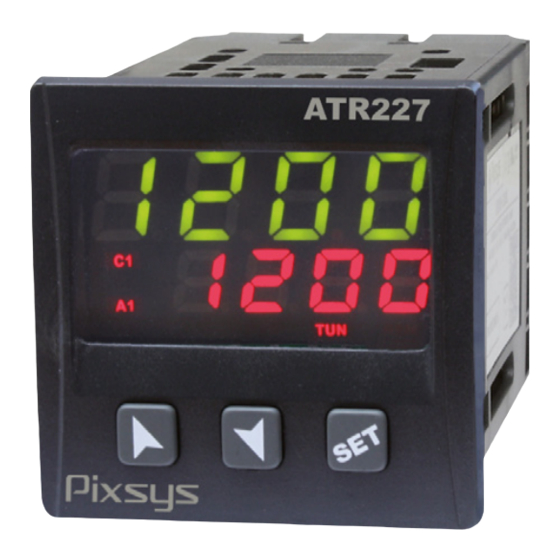
Related Manuals for Pixsys ATR227 Series


Summary of Contents for Pixsys ATR227 Series
- Page 1 ATR227 Controller / Regolatore User manual / Manuale d’uso...
-
Page 3: Table Of Contents
Index 1 Safety guide lines ............................5 2 Model Identification .............................5 3 Technical Data ...............................5 3.1 General Features ..........................5 3.2 Hardware Features ..........................6 3.3 Software Features ..........................6 4 Dimensions and Installation ........................7 5 Electrical wirings ............................7 5.1 Wiring diagram ............................8 6 Display and Keys Functions ........................10 6.1 Numeric Indicators (Display) ...................... - Page 4 Sommario 1 Norme di sicurezza ............................ 30 2 Identificazione del modello ........................30 3 Dati tecnici ..............................30 3.1 Caratteristiche generali ........................30 3.2 Caratteristiche Hardware ........................31 3.3 Caratteristiche Software .........................31 4 Dimensioni ed installazione ........................32 5 Collegamenti elettrici..........................32 5.1 Schema di collegamento ........................
-
Page 5: Safety Guide Lines
Introduction Thank you for choosing a Pixsys controller. With the ATR227 Pixsys model Pixsys makes available in a single device multiple options related to sensor input and actuators command in addition to the extended power range 24..230 Vac/Vdc. With the various selectable sensors and the output con-... -
Page 6: Hardware Features
3.2 Hardware Features 24..230 Vac/Vdc ±15% Power supply Consumption: 5.5 VA. 50/60 Hz 1: AN1 Configurable via sof- (25 °C) Tolerance tware. Input: Thermocou- +/-0.3% ±1 digit (su F.s.) for ther- ple type K, S, R, J, T, E, N, B. mocouple, thermoresistance and Automatic compensation of V / mA. -
Page 7: Dimensions And Installation
Dimensions and Installation ATR227 90 mm 51 mm Dima di foratura 46 x 46 mm Frontal panel cut-out rou de panneau Spessore suggerito 2 ÷ 6 Suggested thickness 2 ÷ 6 Electrical wirings Although this controller was designed to resist electromagnetic interferences in industrial environments, please observe following safety guidelines: • Separate the control line from the power wires. -
Page 8: Wiring Diagram
5.1 Wiring diagram ATR227-10ABC ATR227-12ABC Power Supply 24..230 Vac/dc Switching power supply with extended range ±15% 50/60 Hz – 5,5 VA (galvanically insulated). AN1 Analogue Input For thermocouples K, S, R, J, T, E, N, B. • Comply with polarity • For possible extensions, use compensated cable and terminals suitable for the thermocouples used(compensated) • When shielded cable is used, it should be grounded at one... - Page 9 Examples of connection for Volt and mA inputs PRESSURE TRANSMITTER For linear signals 0/4..20 mA with three-wires SENSORE DI PRESSIONE +12V sensors. 30mA Comply with polarity: A= Sensor output 4..20mA B= Sensor ground C= Sensor supply (+12Vdc / 30mA) PRESSURE TRANSMITTER SENSORE DI PRESSIONE For linear signals 0/4..20 mA with external power supply for sensor.
-
Page 10: Display And Keys Functions
SSR output SSR command output 12 V / 30 mA. Digital Input PNP digital input. Digital input according to parameter dGti . To activate the digital input, shortcircuit pins 4 and 6. Display and Keys Functions 6.1 Numeric Indicators (Display) Normally displays the process. -
Page 11: Keys
6.3 Keys • Increases main setpoint • During configuration phase, allows to slide through parameters. Together it modifies them. with • Pressed after increases alarm setpoint • Decreases main setpoint • During configuration phase, allows to slide through parameters. Together it modifies them. -
Page 12: Automatic Tuning
7.4 Automatic Tuning Automatic tuning procedure has been conceived to give user the possibility to have a clear regulation also without knowledge of PID regulation algorithm. Setting Auto on parameter 8 P. i .d. , the controller will check process oscillations and will modify PID parameters. -
Page 13: Regulation Control (Only On Atr227-12Abc)
manual mode if digital input active, otherwise the regulation is automatic.. • Act.t. : (Action Type) heating regulation with inactive digital input; Cooling regulation with active digital input; • o.rSt : (Outputs Reset) allows to reset the outputs if Manual reset should be configured for command output and/or alarm outputs. - Page 14 At 50% power, the modulation time is 40ms: Load voltage • 1 firing cycle (20ms at 50Hz) • 1 firing cycle (20ms at 50Hz) For a setpoint less than 50% : T NF 50% power T F = T NF • The firing time remains constant (1 cycle) • The non-firing and modulation time increases T NF...
-
Page 15: Configuration
Fixed Phase angle control F.PH.A. If this mode is active, the regulation is done as per “time control” ( tiME ), but during the activation it is managed a fixed choking selected on parameter 45 F.P.A.P... Configuration For configuration parameters see par. 10. Press Display Display 1 shows 0000 with... -
Page 16: Table Of Configuration Parameters
Table of Configuration Parameters The parameters list below can be entered by passwords 1234 (for standard) and 5678 (for advanced). Enter password 1357 to access the complete list Sensor (Password 1234) SEN. Analogue input configuration Tc-K (Default) -260 °C..1360 °C Tc.K Tc-S -40 °C..1760 °C... - Page 17 Lower Linear Input (Password 1234) Lo.L.i. Analogue input lower range limit only for linear signals. Ex.: with input 4...20 mA this parameter takes value associated to 4 mA. -999..+9999 [digit ] (degrees.tenths for temperature sensors), Default: 0. Upper Linear Input (Password 1234) up.L.i.
- Page 18 Gain Calibration (Password 5678) G.caL. Value multiplied to the process value to calibrate the working point. Ex: to correct the range from 0...1000°C showing 0...1010°C, set the parameter to -1.0. -99.9%..+100.0%, Default: 0.0. Command Hysteresis (Password 1234) c. HY. Hysteresis in ON/OFF -999..+999 [digit1] (degrees.tenths for temperature sensors).
- Page 19 Softstart Gradient (Password 5678) Sft.G. Rising gradient for Soft-Start Disabled. Default 1-9999 (degrees/hour). Softstart Time (Password 5678) S.tim. Max. Softstart duration: the process will follow the gradient only for the time set on parameter, than moves to the max. power. Disabled.
- Page 20 Alarm 1 Hysteresis (Password 1234) a. 1 .Hy. -99.9..99.9 °C/°F. Default: 0.5.°C Alarm 1 Led (Password 5678) a. 1 .Ld. Defines the state of A1 led corresponding to the relative contact ON with open contact o.c. ON with closed contact (Default) c.c.
- Page 21 Alarm 2 State Output (Password 1234) A.2.5.o Alarm 2 output contact and intervention type. (N.O. Start) Normally open, active at start (Default) n.o. s. (N.C. Start) Normally closed, active at start n.c. s. (N.O. Threshold) Normally open, active on reaching alarm n.o.
- Page 22 Output Control Type (Password 5678) o.cL.t. Select output control type in case of PID regulation Time control Default tiME Burst fire control bSt.F. Advanced Burst fire control A.bt.F. Phase angle control PHs.A. Fixed Phase angle control F.PH.A. Phase Displacement (Password 5678) PHS.d.
- Page 23 Cycle Time (Password 5678) c.t. (for P.I.D. on remote control switch 15 sec., for P.I.D. on SSR 1 sec.) 1-300 seconds (Default:15s) If par.6 c.out is set as c.SSr , (Default:2s). Lower Limit Output Percentage (Password 5678) L.L.o.P. Selects min. value for command output percentage 0..100%, Default: 0%.
-
Page 24: Alarm Intervention Modes
Alarm Intervention Modes Absolute Alarm or Threshold Alarm ( selection) a. AL. Alarm Spv Absolute alarm with controller in Hysteresis parameter heating functioning (Par. 7 Act.t. selected > 0 Heat ) and hysteresis value greater than “0” (Par.29 A. 1 .HY. > 0).* Time Alarm output... - Page 25 Band Alarm ( selection) b. aL. Alarm Spv Alarm Spv Hysteresis parameter > 0 Band alarm hysteresis value greater than “0” (Par.29 A. 1 .HY. > 0).* Time Alarm output Hysteresis parameter < 0 Comand Spv Alarm Spv Alarm Spv Band alarm hysteresis value less than “0”...
-
Page 26: Table Of Anomaly Signals
Lower Deviation Alarm ( selection) L.d.aL. Comand Spv Hysteresis Lower deviation alarm value of alarm parameter > 0 setpoint greater than “0” and hysteresis Alarm Spv Alarm Spv value greater than “0” (Par.29 A. 1 .HY. > 0).** Time Alarm output Hysteresis... -
Page 27: Configuration Easy-Up
Configuration EASY-UP To simplify the setting of parameters and the integration of the different components involved in the control system, Pixsys introduces the EASY-UP coding which allows to set sensors and/or command outputs in one single step. By means of the code listed in the data sheet enclosed to the sensor or actuator (SSR, motorized valve, etc.) the EASY-UP coding will set the relevant main parameters on... - Page 28 Command Hysteresis (Password 1234) c. HY. Command Led (Password 5678) c. Ld. Command State Error (Password 5678) c. S.e. Command Setpoint Protection (Password 1234) c. s.p. Command Reset (Password 5678) c. re. Command Delay (Password 5678) c. de. Automatic / Manual (Password 1234) au.ma.
- Page 29 Upper Limit Output Percentage (Password 5678) U.L.o.p. Setpoint Deviation Tune (Password 5678) s.d.tu. Max Gap Tune (Password 5678) m.G.tu. Minimum Proportional Band (Password 5678) mn.p.b. Maximum Proportional Band (Password 5678) ma.p.b. Minimum Integral Time (Password 5678) mn.i.t. Notes / Updates User manual - ATR227 -...
-
Page 30: Norme Di Sicurezza
Introduzione Grazie per aver scelto un regolatore Pixsys. Con il modello ATR227 Pixsys rende disponibile in un singolo strumento tutte le opzioni relative alla connessione dei sensori e al comando di attuatori, con in aggiunta un’utile alimentazione a range esteso da 24..230 Vac/Vdc. Con le molteplici sonde selezionabili e l’uscita configurabile come relè... -
Page 31: Caratteristiche Hardware
3.2 Caratteristiche Hardware Alimentazione a range este- Alimentazione so 24..230 Vac/Vdc ±15% Consumo: 5.5 VA. 50/60 Hz 1: AN1 Configurabile via sof- Tolleranza (25 °C) tware. Ingresso: Termocop- +/-0.3% ±1 digit (su F.s.) per termo- pie tipo K, S, R, J, T, E, N, B. coppia, termoresistenza e V / mA. -
Page 32: Dimensioni Ed Installazione
Dimensioni ed installazione ATR227 90 mm 51 mm Dima di foratura 46 x 46 mm Frontal panel cut-out rou de panneau Spessore suggerito 2 ÷ 6 Suggested thickness 2 ÷ 6 Collegamenti elettrici Benché questo regolatore sia stato progettato per resistere ai più gravosi disturbi presenti in ambienti industriali è... -
Page 33: Schema Di Collegamento
5.1 Schema di collegamento Di seguito sono riportati i collegamenti dei tre modelli disponibili. ATR227-10ABC ATR227-12ABC Alimentazione Alimentazione switching a range esteso 24..230 Vac/dc ±15% 50/60 Hz – 5,5 VA (con isolamento galvanico). Ingresso analogico AN1 Per termocoppie K, S, R, J, T, E, N, B. • Rispettare la polarità. - Page 34 Esempi di collegamento per ingressi Volt e mA PRESSURE TRANSMITTER Per segnali normalizzati in corrente 0/4..20 mA con SENSORE DI PRESSIONE +12V sensore a tre fi li. 30mA Rispettare le polarità: A= Uscita sensore 4..20mA B= Massa sensore C= Alimentazione sensore (+12Vdc / 30mA) PRESSURE TRANSMITTER SENSORE DI PRESSIONE Per segnali normalizzati in corrente 0/4..20 mA con...
-
Page 35: Funzione Dei Visualizzatori E Tasti
Uscita SSR Uscita comando SSR portata 12 V / 30 mA. Ingresso digitale Ingresso digitale PNP Ingresso digitale da parametro dGti . Per attivare l’ingresso digitale cortocircuitare i morsetti 4 e 6. Funzione dei visualizzatori e tasti 6.1 Indicatori numerici (Display) Normalmente visualizza il processo. -
Page 36: Tasti
6.3 Tasti • Incrementa il setpoint principale. • In fase di configurazione consente di scorrere i parametri. Insieme al tasto li modifica. • Premuto dopo il tasto incrementa i setpoint di allarme. • Decrementa il setpoint principale. • In fase di configurazione consente di scorrere i parametri. Insieme al tasto li modifica. • Premuto dopo il tasto decrementa i setpoint di allarme. Permette di visualizzare i setpoint di allarme e di entrare nella funzione di lancio del Tuning. -
Page 37: Lancio Del Tuning Automatico
7.4 Lancio del Tuning Automatico La procedura di tuning automatico nasce dall’esigenza, da parte dell’utente,di avere una regolazione precisa, senza dover necessariamente conoscere il funzionamento dell’algoritmo di regolazione PID. Impostando Auto sul parametro 8 P. i .d. , il regolatore analizza le oscillazioni del processo e modifica, se necessario, i parametri PID. -
Page 38: Funzioni Da Ingresso Digitale
7.7 Funzioni da Ingresso digitale L’ATR227 integra alcune funzionalità relative all’ingresso digitale, che può essere abilitato utilizzando il parametro 25 dGt. i . • 2.SPv. : Cambio setpoint a due soglie: con ingresso digitale attivo l’ATR227 regola su SET2, altrimenti regola su SET1; • run. - Page 39 Burst fire control bSt.F. Il controllo “Burst fire” (1 ciclo) permette di gestire la potenza sul carico attraverso l’erogazione di una sequenza completa di sinusoidi. Al 50% di potenza, il tempo di modulazione è 40ms: Load voltage • 1 sinusoide ON (20ms at 50Hz) • 1 sinusoide OFF (20ms at 50Hz) Per potenze inferiori al 50%: T NF 50% power...
-
Page 40: Accesso Alla Configurazione
Phase angle control PHs.A. La regolazione, in questa modalità, avviene attraverso la parzializzazione di fase 25% Power Usando un SSR no zero-crossing l’ATR227 si sincronizza con la tensione di alimentazione 50% Power (necessariamente AC) e determina quando attivare l’uscita per creare la giusta parzializ- 75% Power zazione. -
Page 41: Caricamento Valori Di Default
8.1 Caricamento valori di default Questa procedura permette di ripristinare le impostazioni di fabbrica dello strumento. Premere Effetto Eseguire Su display 1 compare 0000 con la 1° cifra lampeggiante, mentre sul display 2 compare per 3 secondi PASS . Si modifica la cifra lampeggian- te si passa alla successiva con il Inserire la password 9999 . - Page 42 Decimal Point (Password 1234) d.P. Selezione il tipo di punto decimale visualizzato Nessun decimale visualizzato Default Un decimale visualizzato Due decimali visualizzati 0.00 Tre decimali visualizzati 0.000 Degree (Password 1234) deGr. Gradi Centigradi (Default) c Gradi Fahrenheit f Lower Linear Input (Password 1234) Lo.L.i.
- Page 43 Upper Limit Setpoint (Password 1234) up.L.S. Limite superiore impostabile per il setpoint -999..+9999 [digit ] (gradi per sensori di temperatura), Default: 1750. Offset Calibration (Password 5678) o.cAL. Calibrazione offset. Valore che si somma o sottrae al processo visualizzato (es: normalmente corregge il valore di temperatura ambiente). -999..+1000 [digit ] per sensori normalizzati e potenziometri.
- Page 44 Command Delay (Password 5678) c. de. Ritardo comando (solo in funzionamento ON / OFF). -900..+900 secondi. Default: 0. Negativo: ritardo in fase di spegnimento. Positivo: ritardo in fase di accensione. Automatic / Manual (Password 1234) au.ma. Abilita la selezione automatico/manuale. Disabilitato (Default) dis.
- Page 45 Assoluto / soglia, riferito al processo A. AL. Allarme di banda b. AL. Allarme di deviazione superiore H.d.AL. Allarme di deviazione inferiore L.d.AL. Alarm 1 State Output (Password 1234) A.I .5.o Contatto uscita allarme 1 e tipo intervento. (N.O. Start) Normalmente aperto, operativo dallo start (Default) n.o.
- Page 46 Alarm 1 Delay (Password 5678) a. 1 .de. Ritardo allarme 1. -900..+900 secondi. Default: 0. Negativo: ritardo in fase di uscita dall’allarme. Positivo: ritardo in fase di entrata dell’allarme. Alarm 2 (Password 1234) AL.2 Selezione allarme 2. Disabilitato (Default) dis. Assoluto / soglia, riferito al processo A.
- Page 47 Alarm 2 Reset (Password 5678) a2.re. Tipo di reset del contatto dell’allarme 2 Automatic Reset (Default) are. Reset manuale (riarmo/reset manuale da tastiera) mre. Reset Manuale memorizzato (mantiene lo stato del relè anche dopo un mre.s. eventuale mancanza di alimentazione) Alarm 2 Delay (Password 5678) a.2.de.
- Page 48 Proportional Band (Password 5678) p.b. Banda proporzionale. Inerzia del processo °C/°F. 0 ON / OFF se t.i. uguale a 0 (Default) 1-9999 °C/°F Integral Time (Password 5678) i.t. Tempo integrale. Inerzia del processo in secondi. 0.0-999.9 secondi (0 = integrale disabilitato), Default 0.0 Derivative Time (Password 5678) d.t.
-
Page 49: Modi D'intervento Allarme
Minimum Proportional Band (Password 5678) mn.p.b. Seleziona il valore minimo di banda proporzionale impostabile dal tune automatico. 0.0..100.0°C/°F. Default: 5.0°C Maximum Proportional Band (Password 5678) ma.p.b. Seleziona il valore massimo di banda proporzionale impostabile dal tune automatico. 0.0..300.0°C/°F. Default: 50.0°C Minimum Integral Time (Password 5678) mn.i.t. - Page 50 Time Allarme assoluto con regolatore in funziona- Alarm Spv mento freddo Hysteresis (Par.7 Act.t. selezionato ooL ) e valore di parameter < 0 isteresi minore di “0”(Par.29 A. 1 .HY. < 0).* Alarm output Allarme di Banda (selezione b. aL. Alarm Spv Hysteresis parameter...
- Page 51 Comand Spv Comand Spv Alarm Spv Alarm Spv Alarm Spv Alarm Spv Allarme di deviazione superiore valore di Hysteresis setpoint allarme minore di “0” e valore di parameter > 0 isteresi maggiore di “0” (Par.29 A. 1 .HY. > 0).** Time Alarm output...
-
Page 52: Tabella Segnalazioni Anomalie
Configurazione EASY-UP Per semplificare il più possibile il lavoro di parametrizzazione della catena di controllo, Pixsys presenta una nuova modalità a codici che consente di configurare con un unico e semplice passaggio ingressi sonda e/o uscite di comando. La modalità EASY-UP tramite il codice presente sulla documentazione tecnica allegata al sensore o all’attuatore (SSR, valvola-motorizzata, ecc..) configura sullo strumento... -
Page 53: Promemoria Configurazione
2301 TC J (-100..600°C); PID tune automatico su SSR; Allarme 1 assoluto su Q1 2400 TC K (-100..850°C); ON/OFF con isteresi 1°C su Q1; Allarme 1 assoluto su Q2 2401 TC K (-100..850°C); PID tune automatico su SSR; Allarme 1 assoluto su Q1 Promemoria configurazione Data: Modello ATR227... - Page 54 Alarm 1 Setpoint Protection (Password 1234) a. 1 .sp. Alarm 1 Reset (Password 5678) a1.re. Alarm 1 Delay (Password 5678) a. 1 .de. Alarm 2 (Password 1234) AL.2 Alarm 2 State Output (Password 1234) A.2.5.o Alarm 2 Hysteresis (Password 1234) a.2.Hy.
- Page 56 Read carefully the safety guidelines and programming instructions contained in this manual before using/connecting the device. Prima di utilizzare il dispositivo, leggere con attenzione le informazioni di sicurezza e settaggio contenute in questo manuale. PIXSYS s.r.l. www.pixsys.net sales@pixsys.net - support@pixsys.net online assistance: http://forum.pixsys.net 2300.10.218-RevA Software Rev. 1.06 300914...
Need help?
Do you have a question about the ATR227 Series and is the answer not in the manual?
Questions and answers