
Summary of Contents for Kipor KP310V1.0
- Page 1 KP310V1.0 Controller Operation Manual Model KP310V1.0 Model KP310V1.0 www.kipor.com Version No.:KP310.1.1.0 July 20 , 2011...
-
Page 2: Table Of Contents
KP310V1.0 Controller Operation Manual Index 1. Brief Introduction......................... - 1 - 2. Model Nomenclature Explained ..................- 1 - 3. Performance and Features ....................- 1 - 4. Specifications ........................- 2 - 5. Operation..........................- 3 - 5.1 Function of keys......................- 3 - ... -
Page 3: Brief Introduction
KP310V1.0 Controller Operation Manual 1. Brief Introduction The KP310V1.0 controller has the function of manual/remote start and stop genset, data measurement, alarm and protection. The KP310V1.0 can display detailed genset running and alarming data through LED digit display in five numbers. RS232 interface with the host computer, can start, stop genset and display real-time running data through the host computer. -
Page 4: Specifications
KP310V1.0 Controller Operation Manual ☞ Modular structure, flame-retardant ABS shell, pluggable terminals, embedded installation, compact structure and easy installation 4. Specifications Working Voltage 12VDC (8~16VDC) Voltage measurement AC Input Voltage: Phase voltage 10~290VAC RMS Precision level:2.0 Three-phase four-line Three-phase three-line... -
Page 5: Operation
KP310V1.0 Controller Operation Manual 5. Operation 5.1 Function of keys Genset is running, press to stop genset, when genset is in alarming status, press to reset. Stop/Reset In “System Set” mode, press to return to the previous sub-menu. Press to set genset in “Manual” Mode. - Page 6 KP310V1.0 Controller Operation Manual maintenance, and reset it. 5 In the “Fuel Filter Running Time” mode, press for 5 seconds, it will clear alarm of fuel filter maintenance, and reset it. 6 In the “Air Filter Running Time” mode, press for 5 seconds, it will clear alarm of air filter maintenance, and reset it.
-
Page 7: Controller Layout
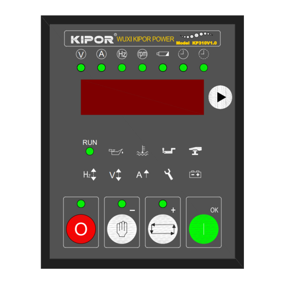
KP310V1.0 Controller Operation Manual 5.2 Controller Layout Model KP310V1.0 Model KP310V1.0 Voltage Current Frequency Revolutions Battery Running Maintenance voltage time time Low Oil High Water Starting Emergency Pressure Temperature Failure Stop Frequency Voltage Current Maintenance Charge High/Low High/Low High/Low Failure... -
Page 8: Main Display
KP310V1.0 Controller Operation Manual 5.2.1 Main Display Press , it will display voltage, current, frequency, revolution, battery voltage, run time and maintenance time. Note: Battery charging voltage, switch value input/output state and system delay state is also available with RS232 Port. - Page 9 KP310V1.0 Controller Operation Manual Press to display running parameter, which shows as following: Voltage Three-phase four-line Three-phase three-line Single-phase two-line Two-phase three-line Double-voltage output alternative 120V output equals to single-phase two-line 240V output equals to two-phase three-line Current Three-phase four-line...
- Page 10 KP310V1.0 Controller Operation Manual Three-phase three-line Single-phase two-line Two-phase three-line Double-voltage output alternative 120V output equals to single-phase two-line 240V output equals to two-phase three-line Frequency Revolution ✪Note: If the “Revolution low” is set as zero, then the speed won’t be displayed..
-
Page 11: Parameters Set" Menu
KP310V1.0 Controller Operation Manual Air filter 5.2.2 “Parameters Set” menu The followings parameters are included in “Parameters Set” menu: ★NUMBER OF ENGINE FLYWHEEL ★TRIPPING SPEED ★TRIPPING FREQUENCY ★TRIPPING CHARGING VOLTAGE ★START TIMES ★TRIPPING OIL PRESSURE DELAY ★MAX. STARTING TIME ★UNDER SPEED ★OVER SPEED... -
Page 12: Manual Operation
Press to get back to “Parameters Set” menu. 5.3 Manual Operation When the KP310V1.0 controller is working, it is initialized to “Manual” Mode, with indicator lighting. Press or turn the ignition lock to start genset. -
Page 13: Remote Operation
Press to stop genset. 5.4 Remote Operation When the KP310V1.0 controller is working, it is initialized to the “Manual” Mode. Press to login into the remote mode. Start steps: Preheat relay output, meanwhile the preheating timer start counting down. If the preheating time is set as zero, the relay won’t output. -
Page 14: Alarm
KP310V1.0 Controller Operation Manual 6.1 Alarm In the following alarms, relevant LED twinkles, but genset keeps running. Type Description When oil filter is overtime than the maintenance value, there will Oil filter overtime be an oil filter overtime alarm, maintenance LED twinkles. -
Page 15: Emergency Stop Alarms
KP310V1.0 Controller Operation Manual 6.3 Emergency stop alarms After detecting the emergency stop alarms, relevant LED twinkles, and genset will be stopped instantly. Buzzer will give alarms. Type Description If genset frequency is larger than the set value, over frequency LED Over twinkles, genset will be stopped instantly. -
Page 16: Wiring
KP310V1.0 Controller Operation Manual 7. Wiring The back panel of KP310V1.0 controller is as follows: 28 27 26 25 23 22 21 20 19 Current Genset Voltage (Rated 5mA) ICOM 21 20 KP310V1.0 GENSET CONTROLLER 9 10 11 12 13 14 15 16 17 18... -
Page 17: Parameter Set
KP310V1.0 Controller Operation Manual Programmable relay output 2 1.0mm Normal open output, rated current:1A Communication port-DIR 1.0mm Genset can communicate with PC through Communication port-TXD 1.0mm RS232 communication adapter. Genset can communicate with remote Communication port-RXD 1.0mm controller through RS485 communication Communication port-GND 1.0mm... -
Page 18: Parameters Set List
KP310V1.0 Controller Operation Manual If there is no operation for more than 60s, system will automatically exit Parameter Set menu, and enter the System Operation menu. 8.1 Parameters Set list Model KP310V1.0 Model KP310V1.0 Parameter Code Data Parameters Code Range... - Page 19 KP310V1.0 Controller Operation Manual Set Output 1 or Set Output 2 is setted as “ Genset Preheat ”, it Preheat delay ○○●●○● 0-100 0.1s works when genset starts, controller start to count down.. Within the safety delay, under oil pressure, high water temperature, Safety Delay ○○●●●○...
- Page 20 KP310V1.0 Controller Operation Manual Communication Communication Communication address with the ●○○○○● 0-32 Address Maintenance Fuel filter Engine Fuel filter replace maintenance ●○○○●○ 0-65535 0.1Hr 5000 countdown time Air filter Engine filter replace maintenance ●○○○●● 0-65535 0.1Hr 5000 countdown time Oil filter...
- Page 21 KP310V1.0 Controller Operation Manual 3-Genset Start 4-Genset Idle 5-Genset Running 6-Genset Electric Parameters Normal 7-System Warning Alarm 8-System Delay Stop Alarm 9-System Stop Alarm 10-System Alarm 11-Manual Mode 12-Remote Mode 13-Oil Filter Overtime 14-Fuel Filter Overtime 15-Air Filter Overtime 16-Start Failure...
- Page 22 KP310V1.0 Controller Operation Manual Regulate the Gain to display the L2 Phase ●●○○●● 0-2047 1024 same L2 phase voltage on the Voltage Gain controller with the actual voltage. Regulate the Gain to display the L3 Phase ●●○●○○ 0-2047 1024 same L3 phase voltage on the Voltage Gain controller with the actual voltage.
-
Page 23: Programmable Output List
KP310V1.0 Controller Operation Manual 8.2 Programmable output list 8.2.1 Remote set Terminal “8” has “Remote” function; the function is only valid in “Remote mode”. Contents Note 0—Remote start normally Normally Open : in the default state, input signal open open ( high potential) ;... -
Page 24: Set Input
KP310V1.0 Controller Operation Manual 8.2.1.5 Remote start & stop normally open In the “Remote mode ”,After Terminal “8” is closed ( low potential),genset start after remote start delay(parameters can be setup).Terminal “8” open ( high potential),genset stop after Remote Stop Delay(parameters can be setup). -
Page 25: Programmable Output List
KP310V1.0 Controller Operation Manual 8.2.2.4Stop normally closed After Terminal is open ( high potential),confirmed by Set Input Fault Delay, stop the alarm immediately. Relevant set input faults LED light up. 8.3 Programmable output list KP310_1.00 controller has two terminals(terminal 17、18) to customers to set different parameters. -
Page 26: Commission
KP310V1.0 Controller Operation Manual 9. Commission Before commission, please check as follows: 1、Check all connections and wires; 2、Right connection with batteries; 3、Right connection of Emergency Stop button with battery; 4、Take proper measures to prevent engine from starting such as dismantle fuel valve connections, then connect with battery, select manual mode. -
Page 27: Installations
KP310V1.0 Controller Operation Manual 11. Installations KP310V1.0 controller is panel mounting. Dimensions are as follows: - 25 -... -
Page 28: Trouble Shooting
KP310V1.0 Controller Operation Manual 12. Trouble shooting Troubles Solutions Controller no electricity Check batteries Check controller connections Check DC fuse genset Stop Check if water temperature is over high Check AC Generator voltage Check DC fuse controller emergency stop Check if emergency function is OK... -
Page 29: Physical Layer Of Communication Protocol
KP310V1.0 Controller Operation Manual 13.1 Physical Layer of Communication Protocol Comm port: EIA/TIA-232-E Comm mode: asynchronous Comm speed: 9600bps Parity check: no Start bit: 1 Data bit: 8 Stop bit: 1 Data period: <5ms Frame-frame period: >100ms Comm timeout: 200ms... -
Page 30: Comm Rtu
KP310V1.0 Controller Operation Manual 13.3 Comm RTU This communication protocol uses RTU (remote terminals communication unit ) mode, namely binary. Address field Function field Data field Data adjustment field Slave address Function code Data length Data CRC16 2Bytes 2Bytes 2Byte... -
Page 31: Appendix 1 Crc16-Ccitt Sheet
KP310V1.0 Controller Operation Manual Appendix 1 CRC16-CCITT Sheet unsigned int CRC16CCITT[]= 0x0000, 0x1021, 0x2042, 0x3063, 0x4084, 0x50a5, 0x60c6, 0x70e7, 0x8108, 0x9129, 0xa14a, 0xb16b, 0xc18c, 0xd1ad, 0xe1ce, 0xf1ef, 0x1231, 0x0210, 0x3273, 0x2252, 0x52b5, 0x4294, 0x72f7, 0x62d6, 0x9339, 0x8318, 0xb37b, 0xa35a, 0xd3bd, 0xc39c, 0xf3ff, 0xe3de,... -
Page 32: Appendix 2 Crc16-Ccitt
KP310V1.0 Controller Operation Manual Appendix 2 CRC16-CCITT /******************************************************************* Function: generate CRC16CCITT code Input: = mouse cursor points to first byte DataLen =data length Output: CRC16CCITT *******************************************************************/ Unsigned int CRC16CCITT (unsigned char *p, unsigned int DataLen) Unsigned int crc16=0; Unsigned int i;... -
Page 33: Appendix 3 Wiring Diagram
KP310V1.0 Controller Operation Manual Appendix 3 Wiring Diagram 1) 3-Phase 4-Line Generator Load Comm_VCC Comm_GND ICOM 21 20 KP310V1.0 GENSET CONTROLLER 9 10 11 12 13 14 15 16 17 18 120/240 Select High Temp Fuel Crank Start sw Oil Press Aux_In1 Aux_In2... -
Page 34: 3-Phase 3-Line
KP310V1.0 Controller Operation Manual 2) 3-Phase 3-Line Load Generator ICOM 21 20 KP310V1.0 GENSET CONTROLLER 1 2 3 4 5 6 7 8 9 10 11 12 13 14 15 16 17 18 - 32 -... -
Page 35: 1-Phase 2-Line
KP310V1.0 Controller Operation Manual 3) 1-Phase 2-Line Load Generator ICOM 21 20 KP310V1.0 GENSET CONTROLLER 9 10 11 12 13 14 15 16 17 18 - 33 -... -
Page 36: 2-Phase 3-Line
KP310V1.0 Controller Operation Manual 4) 2-Phase 3-Line Load Generator ICOM 21 20 KP310V1.0 GENSET CONTROLLER 9 10 11 12 13 14 15 16 17 18 - 34 -...
Need help?
Do you have a question about the KP310V1.0 and is the answer not in the manual?
Questions and answers
Генератор работает, но не выдаёт напряжение. Почему?