Table of Contents
Advertisement
INSTALLATION AND COMMISSIONING INSTRUCTIONS
Digital Voltage Controller, DVC 310
DEIF A/S · Frisenborgvej 33 · DK-7800 Skive · Tel.: +45 9614 9614 · Fax: +45 9614 9615 · info@deif.com · www.deif.com
● Mounting
● Terminals and wiring
● Commissioning, using the EasyReg
software
Document no.: 4189340917C
SW version:
Advertisement
Table of Contents

Related Manuals for Deif DVC 310


Summary of Contents for Deif DVC 310
- Page 1 DEIF A/S · Frisenborgvej 33 · DK-7800 Skive · Tel.: +45 9614 9614 · Fax: +45 9614 9615 · info@deif.com · www.deif.com isenborgvej 33 · DK-7800 Skive · Tel.: +45 9614 9614 · Fax: +45 9614 9615 · info@deif.com · www.deif.com Document no.: 4189340917C...
-
Page 2: Table Of Contents
DVC 310 installation and commissioning instructions 4189340917 UK 1. Introduction 1.1. About the Installation and commissioning instructions................3 1.1.1. General purpose ...........................3 1.1.2. Intended users ..........................3 1.1.3. Revision information ........................3 1.1.4. Software version ...........................3 1.1.5. Getting technical support.......................3 1.2. Warnings, safety and legal information....................3 1.2.1. -
Page 3: Introduction
The letter at the end of the document number on the front page indicates the revision number of this docu- ment. The latest version of this document can be downloaded at www.deif.com. If you click on the revision letter to the right of the document name, the revision history is displayed. -
Page 4: Safety Issues
Touching the terminals could lead to injury or death. 1.2.3 Factory settings The DVC 310 is delivered pre-programmed from the factory with a set of factory settings. These are based on average values and are therefore not necessarily correct for your alternator. All DVC 310 parameters must be checked before running the installation. -
Page 5: Installation, Mounting And Wiring
2.2.1 Mounting the DVC 310 The DVC 310 is normally located in the generator terminal box. It is designed for mounting behind the panel. Mounting hardware consists of four thread-forming screws, Ø 6 mm, that pass through the plastic shell of the DVC 310 and go into the terminal box of the alternator. -
Page 6: Dimensions
In order for the DVC 310 to be CE (European Community) compliant, the end-user should follow a few rec- ommendations concerning mounting of the unit. The DVC 310 can be mounted in the terminal box of the alternator (metal enclosure) or directly into the con- trol switchboard. - Page 7 See picture above. The DVC 310 can also be mounted in the terminal box on an alternator. In this case it is also important to use shielded CAN bus cable and make sure that the above recommendations are followed as well.
-
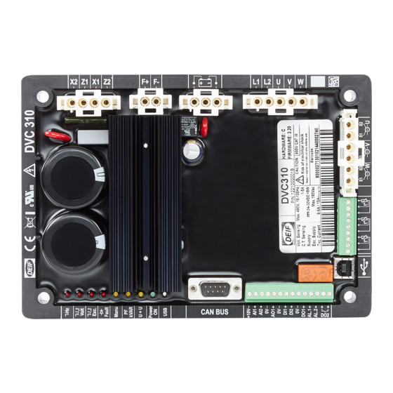
Page 8: Wiring And Terminals
DVC 310 installation and commissioning Installation, mounting and wiring instructions 4189340917 UK 2.3 Wiring and terminals 2.3.1 Wiring diagram The numbers in the diagram above indicate the following: 1 Power AREP: Yellow wire on X2 - red wire on Z1 - green wire on X1 - black wire on Z2... - Page 9 DVC 310 installation and commissioning Installation, mounting and wiring instructions 4189340917 UK 4 Voltage sensing Mains voltage: L1 and L2 Alternator voltage - single-phase: V and W Three-phase: U, V and W 5 Current transformer(s) Placing in parallel and measurement: CT on U...
-
Page 10: Human Machine Interface
3.1.1 Communication USB link The EasyReg software and the DVC 310 communicate via a USB cable (Universal Serial Bus). The connection on the DVC 310 is the B type. 3.1.2 Analogue I/O This part of the board allows the operator to use the inputs to make manual settings and the outputs to check certain data or to indicate whether certain AVR functions are working correctly or not. -
Page 11: Digital I/O
DVC 310 installation and commissioning Human Machine Interface instructions 4189340917 UK 3.1.3 Digital I/O I/O name Type Characteristics Pull up input To be connected to 0 V Opened collector Max. current: 60 mA Voltage: 0 to 24 V Dry contact...
Need help?
Do you have a question about the DVC 310 and is the answer not in the manual?
Questions and answers