Table of Contents
Advertisement
Quick Links
Quick Installation Guide
Moxa Americas:
Toll-free: 1-888-669-2872
Tel:
1-714-528-6777
Fax:
1-714-528-6778
Moxa Europe:
Tel:
+49-89-3 70 03 99-0
Fax:
+49-89-3 70 03 99-99
Moxa India:
Tel:
+91-80-4172-9088
Fax:
+91-80-4132-1045
Fl.4, No. 135, Lane 235, Baoqiao Rd., Xindian Dist., New Taipei City,
ICF-1180I Series
Edition 8.1, February 2018
Technical Support Contact Information
www.moxa.com/support
2018 Moxa Inc. All rights reserved.
Moxa China (Shanghai office):
Toll-free: 800-820-5036
Tel:
Fax:
Moxa Asia-Pacific:
Tel:
Fax:
Taiwan, R.O.C
+86-21-5258-9955
+86-21-5258-5505
+886-2-8919-1230
+886-2-8919-1231
P/N: 1802011800019
*1802011800019*
Advertisement
Table of Contents

Related Manuals for Moxa Technologies ICF-1180I Series


Summary of Contents for Moxa Technologies ICF-1180I Series
- Page 1 ICF-1180I Series Quick Installation Guide Edition 8.1, February 2018 Technical Support Contact Information www.moxa.com/support Moxa Americas: Moxa China (Shanghai office): Toll-free: 1-888-669-2872 Toll-free: 800-820-5036 Tel: 1-714-528-6777 Tel: +86-21-5258-9955 Fax: 1-714-528-6778 Fax: +86-21-5258-5505 Moxa Europe: Moxa Asia-Pacific: Tel: +49-89-3 70 03 99-0...
-
Page 2: Auto/Manual Baudrate Settings
Auto/Manual Baudrate Settings The ICF-1180I series converts signals back and forth between PROFIBUS and fiber and supports baudrates from 9.6 kbps to 12 Mbps. Engineers do not need to know the baudrate of the connected PROFIBUS device since the ICF-1180I can automatically detect the baudrate of the PROFIBUS device and apply this baudrate directly. -
Page 3: Fiber Link Monitor
Fiber Link Monitor The ICF-1180I series’ Fiber Link Monitor function detects communication errors on either the fiber side or the PROFIBUS side. When a communication error occurs, the corresponding LED will shine red and the relay alarm will activate. -
Page 4: Package Checklist
Using Remote Fiber Diagnosis: Set DIP switch SW8 to the ON position on any ICF-1180I converter and then look at the Ready LED status. A flashing green Ready LED indicates that the Fiber Test has finished. The P1 (Fiber port) LED indicates which side (Tx or Rx) is causing the problem. -
Page 5: Mounting Dimensions (Unit: Mm)
Mounting Dimensions (unit: mm) - 5 -... -
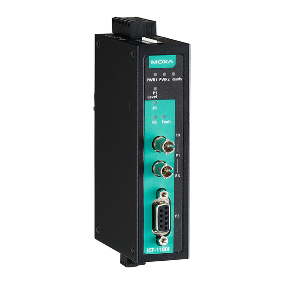
Page 6: Icf-1180I Panel Layouts
ICF-1180I Panel Layouts Top View Bottom View Front View ATTENTION Electrostatic Discharge Warning! To protect the product from damage due to electrostatic discharge, we recommend wearing a grounding device when handling your ICF-1180I. - 6 -... -
Page 7: Wiring The Alarm Contact
To remove the ICF-1180I series from the DIN rail, simply reverse Steps 1 and 2 above. Wiring the Alarm Contact The alarm contact is made up of the two middle contacts of the terminal block on the ICF-1180I’s top panel. -
Page 8: Wiring The Redundant Power Inputs
Wiring the Redundant Power Inputs STEP 1: Insert the negative/positive DC wires into the V-/V+ terminals. STEP 2: To keep the DC wires from pulling loose, use a small flat-blade screwdriver to tighten the wire-clamp screws on the front of the terminal block connector. -
Page 9: Federal Communications Commission Statement
Federal Communications Commission Statement FCC: This device complies with part 15 of the FCC Rules. Operation is subject to the following two conditions: 1. This device may not cause harmful interference, and 2. This device must accept any interference received, including interference that may cause undesired operation. -
Page 10: Dip Switch Settings
L: The length of the fiber optic cable in kilometers. N: The number of converters in the system. A and B: Parameters determined by the transmission speed. Note: To avoid frame conflicts, we recommend setting the PROFIBUS command retry limit ≥ 3, and the slot time < 262128. DIP Switch Settings There are 8 DIP switches on the top panel of the ICF-1180I. -
Page 11: Led Indicators
LED Indicators There are 7 LEDs on the front panel of the ICF-1180I. Color Description Relay Status PWR1/ Solid green Power is on Closed PWR2 Power is off, or power error Open condition exists Ready Solid green Baudrate is detected, Closed converter is ready for communication... - Page 12 Troubleshooting LED Indicators and Fiber Test Color Description Status/Troubleshooting Ready Flashing Fiber diagnosis At least one converter is in Fiber green finished Diagnosis mode; Check PROFIBUS master settings; Tx and Rx cables crossed Flashing Detecting No PROFIBUS node; baudrate No PROFIBUS signal received; Tx and RX crossed over;...
-
Page 13: Fiber Signal Intensity Diagnosis
Fiber Signal Intensity Diagnosis In some circumstances you may need to measure the receive level of fiber optic channels P1 and P2 with a voltmeter, which can be connected while the device is operating (doing so will not affect data transmission). The measurement can be taken with a voltmeter and read on a PLC that uses floating high impedance analog inputs, which allows you to do the following:... - Page 14 When taking measurements, use a standard ungrounded, high-resistance voltmeter. The internal resistance of the measurement sockets is approximately 30 kΩ. Keep in mind that you must not connect the measurement sockets or reference potential to the ICF housing. • Multi-mode: ICF-1180I-M-ST •...
-
Page 15: Specifications
Specifications PROFIBUS Communication PROFIBUS Interface PROFIBUS DP Number of Ports Connector DB9 female Isolation Protection 2 kV Baudrate 9.6 Kbps to 12 Mbps Auto Baudrate Fiber Communication Connector type Distance Single-mode fiber for 45 km Multi-mode fiber for 4 km Support Cable: Single mode: 8.3/125, 8.7/125, 9/125 or 10/125 μm... - Page 16 Regulatory Approvals Safety UL 508 Hazardous Location UL/cUL Class I, Division 2, Groups A, B, C, and D DNV.2.4 (not suitable for installation on a bridge) ATEX Zone 2: Ex nA nC op is IIC T4 Gc IEC 60079-0:2011 Ed.6 IEC 60079-15:2010 Ed.4;...
Need help?
Do you have a question about the ICF-1180I Series and is the answer not in the manual?
Questions and answers