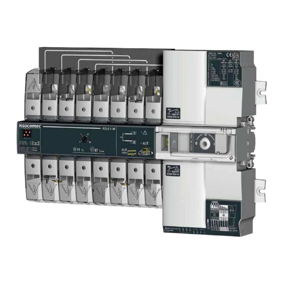
socomec ATyS g M Quick Start
40-160a (4p)
Hide thumbs
Also See for ATyS g M:
- Instruction manual (55 pages) ,
- Installation and operating manual (54 pages) ,
- Quick start (2 pages)
Advertisement
Quick Links
Installation and Commissioning
QUICK START
}}$
3
EN
ATyS
g
M
STEP 1
Cabinet / Back
Plate Installation
Automatic
Transfer Switching Equipment
Preliminary operations
Check the following upon delivery and after removal of the
packaging:
■
Packaging and contents are in good condition.
■
The product reference corresponds to the order.
■
Contents should include:
Qty 1 x ATyS M
Qty 1 x Emergency handle extension ROD
Qty 1 x Set of terminals
Quick Start instruction sheet
Warning
Risk of electrocution, burns or injury to persons and /
or damage to equipment.
This Quick Start is intended for personnel trained in the
installation and commissioning of this product. For further
details refer to the product instruction manual available on
the SOCOMEC website.
■
This product must always be installed and commissioned
by qualified and approved personnel.
■
Maintenance and servicing operations should be
performed by trained and authorised personnel.
■
Do not handle any control or power cables connected to
the product when voltage may be, or may become present
on the product, directly through the mains or indirectly
through external circuits.
■
Always use an appropriate voltage detection device to
confirm the absence of voltage.
■
Ensure that no metal objects are allowed to fall in the
cabinet (risk of electrical arcing).
Failure to observe good enginering practises as well as to
follow these safety instructions may expose the user and
others to serious injury or death.
Risk of damaging the device
■
In case the product is dropped or damaged in any way it
is recommended to replace the complete product.
STEP 3
Accessories
■
Bridging bars and 125A or 160A.
■
Control voltage transformer (400Vac -> 230Vac).
Type
Terminal no.
■
Voltage sensine and power supply TAP.
■
Terminal shrouds.
Inputs
I1: 207 / 208
■
Additionnal aux contact block.
■
Polycarbonate enclosure.
■
Polycarbonate extension box.
■
Power Connection Terminals.
■
Sealable cover.
I1: 207 / 209
I3: 207 / 210
Outputs O1: 63 / 64
www.socomec.com
www.socomec.com/en/atys-g-m
To download, brochures, catalogues and technical manuals.
O2: 73 / 74
Printing informations: 1 color Black. White paper 90g/m
2
.
Printing size: 420x297. Final size 210x297. This page visible first.
A separate sheet for each language.
Non contractual document.
542 932 B - 06/14 - EN
Subject to change without notice.
STEP 2
STEP 3
STEP 4
STEP 5
Connecting the
CONTROL /
CHECK
Programming
POWER section
AUX POWER
terminal
connections
CONTROL / AUX POWER Terminals and wiring
Status of the
Output
Application
Description
contact
characteristics
Network/Network
With priority
Without priority
Dry potential free
contact
Network-Genset.
Automatic retransfer
Manual Retransfer
Network/Network
Source priority 1
Source priority 2
Dry potential free
contact
Network-Genset.
Stop the test on load
Test on load
Network-Network or
AUTO mode
Dry potential free
Network-Generating
contact
set
Automatic mode inhibition
Network-Network or
Product not available :
Resistive load
Network-Generating
- Manual mode
2A 30 Vdc
set
- Command default
0.5A 230Vac
- Electronic default
Pmax : 60W or 125VA
- No source
Umax : 30Vdc or
230Vac
Product available
Network-Genset.
No start command genset
Resistive load
2A 30 Vdc
Generating set starting
0.5A 230Vac
Pmax : 60W or 125VA
Umax : 30Vdc or
230Vac
STEP 6A
STEP 1
Installation
Automatic Operation
Caution: Ensure that the product is installed on a flat rigid surface.
Recommended orientation
STEP 6B
Emergency Manual
Operation
STEP 6C
Recommended
Ok
Padlocking
DIN RAIL
IEC 60715
STEP 2
Power Terminal Connections
It is essential to tighten
DOObWHUPLQDOV LQFOXGLQJ
WKRVHbQRW EHLQJ XVHG
Source supply side
LOAD
Recommended
connection
cross-section
2
2
4
4
6
6
8
8
2
2
4
4
6
6
8
8
1
1
3
3
5
5
7
7
1
1
3
3
5
5
7
7
0.5 to 2.5 mm²
(rigid)
0.5 to 1.5 mm²
Terminal no. Status of
Type
(stranded)
WKHbFRQWDFW
Auxiliary contact
14
11/12/14
12 Changeover switch in position I
11
block
1309 0001
24
21/22/24
21
22 Changeover switch in position II
01/02/04
04
01
02 Changeover switch in position 0
Auxiliary contact
14
11/12/14
11
12
block
1309 0011
24
21/22/24
21
22
01/02/04
04
01
02
13
26
Ok
Ok
Ok
Ok
46
53
73,5
Tighten to avoid
PRYHPHQWbRQbWKH ',1bUDLO
52
104
6 mounting brackets
Posidriv PZ1
1 Nm
6x M6 screw - 2,5 Nm
9ROWDJH WDSV SURYLGH [ PP
They can be fitted in any terminals on the source
supply side. Do not use on the load side when
equipped with a bridging bar.
Load side
bridging bar.
125A: 1309 4006
160A: 1309 4016
Hexagonal Metric
Allen size 4
m
2
5,0 Nm
WG
m
2
*
WG
10 to
70 mm²
15mm
8
5 A AC1
5 A AC1
250 Vac
250 Vac
22 24 21
22 24 21
11 14 12
11 14 12
01 04 02
01 04 02
1309 0001
1309 0011
O1 O2
Ensure that the product is in
Manual Mode (front cover
207208 209 210 63 64 73 74
open).
I1 I2 I3
Recommended
Auxiliary contacts:
Output
Description
connection
characteristics
To fit an AC, the switch must first be put in position 0. An auxiliary contact module comprises: one NO/
cross-section
NC changeover contact for each position (I-0-II). To install use the long screws supplied with the module.
250V AC 5A AC1
30 Vdc 5 A
250V AC 5A AC1
30 Vdc 5 A
0.5 to 2.5 mm²
250V AC 5A AC1
(rigid)
30 Vdc 5 A
250V AC 5A AC1
0.5 to 1.5 mm²
Changeover switch in position I
30 Vdc 5 A
(stranded)
250V AC 5A AC1
Changeover switch in position II
30 Vdc 5 A
250V AC 5A AC1
Changeover switch in position 0
30 Vdc 5 A
340
Padlocking configuration
324
116
The ATyS M is delivered with
padlocking configured to the
18
O position.
MAX : 2
340
326
176
Posidriv PZ2
To allow padlocking in all
positions (I - O - II), configure
WKH $7\6b0 DV IROORZV EHIRUH
installation. (Screw is located
at the back of the product).
Step 1
2
connections.
Posidriv PZ2
2x
2
Posidriv PZ2
Step 2
Step 3
STEP 3
2x
Slotted head 3,5 mm
0,45 Nm
0,5 to 2,5 mm²
Posidriv PZ2
2,2 lb-in 0,25 Nm
0,5 to 1,5 mm²
6 mm
0,5 to 2,5 mm²
0,5 to 1,5 mm²
6 mm
Slotted head 3mm 0,5 Nm
230/127V~
3ph 4wires
230/127V~
3ph 3wires
1309 0001 or 1309 0011
Fitting of auxiliary contacts:
U
Use 20mm
Us
se 20m
m
Use 35mm
screws for
s
sc
crews
r
screws for
1
1
1 module
modu
2 modules
Pozidriv PZ2 - 1 Nm
Advertisement

Related Manuals for socomec ATyS g M


Summary of Contents for socomec ATyS g M
- Page 1 For further supply side. Do not use on the load side when details refer to the product instruction manual available on equipped with a bridging bar. the SOCOMEC website. It is essential to tighten Load side ■...
- Page 2 STEP 4 STEP 5 Check Programming Whilst in manual mode, check the The LED signalling and operation is only active when the product supply is available. wiring and if ok power up the To set the dip switches, it is necessary to open the Auto/Manual cover. product.
Need help?
Do you have a question about the ATyS g M and is the answer not in the manual?
Questions and answers