
Related Manuals for Flight Medical Innovations 60 Series


Summary of Contents for Flight Medical Innovations 60 Series
- Page 1 FLIGHT MEDICAL INNOVATIONS Ltd. FLIGHT 60 VENTILATOR Service Manual Models: SL; DL; iO LIT-0021 Rev. A12 Aug 2016...
- Page 2 TABLE OF CONTENTS FLIGHT 60 Ventilator...
- Page 4 Legal Notice Disclaimer FLIGHT MEDICAL INNOVATIONS Ltd. (FLIGHT MEDICAL) provides this Service Manual in its commitment to help reduce patient risk and injury. However, this manual is not intended to in any way replace or substitute duty of care to a patient, professional responsibility, or professional judgment, nor is it intended to provide any warranty, promise, guarantee, assumption of risk or duty, release, or indemnity.
- Page 5 Legal Notice patient condition. However, equipment surveillance should not replace direct observation of clinical signs. The liability of FLIGHT MEDICAL is subject to and limited to the exclusive terms and conditions as set forth herein. Said liability is limited whether arising out of, or related to, the manufacture and sale of goods, their installation, demonstration, sales representation, use, performance, or otherwise.
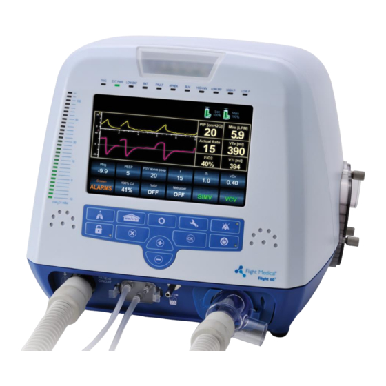
- Page 6 About this Document About this Document This document is a service manual for the FLIGHT 60 and F60 Dual Limb Ventilators, ventilators that provide continuous or intermittent mechanical ventilation support for the care of individuals who require mechanical ventilation. It is intended for technicians who are responsible for maintaining, servicing, and providing troubleshooting assistance for the FLIGHT 60 and F60 Dual Limb Ventilators.
-
Page 7: Table Of Contents
Table of Contents Table of Contents INTRODUCTION ................. 1-1 ................1-1 NTENDED ..................1-1 YMBOLS SAFETY INSTRUCTIONS ..............2-1 ................. 2-1 ENERAL ARNINGS ..................2-3 AUTIONS FUNCTIONAL DESCRIPTION ............... 3-1 .................. 3-1 RONT ANEL 3.1.1 Keypad / Control Buttons ............. 3-2 3.1.2 LED Indicators .............. - Page 8 Table of Contents ............4-10 EPLACING THE OWER UPPLY 4.7.1 Class I Power Supply ............4-10 4.7.2 Class II Power Supply ............4-13 ..........4-14 EPLACING THE RONT ANEL SSEMBLY 4.8.1 Removing the Front Panel Assembly ........4-14 4.8.2 Connecting the Front Panel Assembly ........4-17 ) ..
- Page 9 Table of Contents 4.21.1 Removing the Fuse............. 4-39 4.21.2 Installing the Fuse ............. 4-39 ............4-40 EPLACING THE UBBER UMPERS 4.22.1 Removing the Rubber Bumpers ..........4-40 4.22.2 Installing the Rubber Bumpers ..........4-40 SERVICE/TECHNICAL MENU............... 5-1 ................5-1 DVANCED CREEN ................
- Page 10 Table of Contents ................9-3 NTRODUCTION ................9-3 RROR ESSAGES 10 REPACKAGING AND SHIPPING ............10-1 RGA R ..................10-1 ETURNS 11 SPARE PARTS ................... 11-2 .................. 11-2 LECTRONIC ..............11-5 ECHANICAL SSEMBLIES ..................11-8 ABLES viii | FLIGHT 60 Service Manual...
-
Page 11: Introduction
Introduction Intended Use 1 Introduction This Service Manual (V60-00002-18 Rev. A) provides information for servicing the FLIGHT 60 Ventilator. It is for use by authorized service personnel while installing, servicing, and repairing the ventilator. Intended Use The FLIGHT 60 Ventilator is intended to provide continuous or intermittent mechanical ventilation support for the care of individuals who require mechanical ventilation. - Page 12 Introduction Symbols Symbol Description Extended Screen Technical Screen Nebulizer Port Rear Panel Caution; consult accompanying documents Type BF applied part Temperature limitation Humidity limitation Atmospheric pressure limitation DC – Direct Current AC – Alternating Current USB – Universal Serial Bus LAN –...
-
Page 13: Safety Instructions
Safety Instructions General Warnings 2 Safety Instructions At all times, strictly follow this manual. The safe use of the FLIGHT 60 Ventilator requires full understanding of its operation, and adherence to the manual's instructions. The equipment is only to be used for the purpose specified in section 1.1. - Page 14 Safety Instructions General Warnings Ensure that the oxygen source is not empty before and during the use of the optional Air/Oxygen Entrainment Mixer or Oxygen Blending Bag Kit. As Li-Ion batteries are charged and discharged over time, their ability to hold a charge is decreased with use.
-
Page 15: Cautions
Safety Instructions Cautions Only a FLIGHT MEDICAL approved exhalation valve can be used with the FLIGHT 60 Ventilator. Perform a Circuit Test each time a clean circuit/exhalation valve is installed. This FLIGHT 60 Ventilator has been tested and found to comply with the EMC limits according to the EN60601-1-1-2 standard class B. - Page 16 Safety Instructions Cautions An authorized FLIGHT MEDICAL factory-trained technician must do all service or repairs performed on the FLIGHT 60 Ventilator. Do not open the ventilator or perform service on an open unit while connected to external power. Use standard antistatic techniques while working inside the ventilator or handling any electronic parts.
-
Page 17: Functional Description
Functional Description Front Panel 3 Functional Description Front Panel The front panel contains the control buttons, visual indicators, display screen, and patient circuit connection. There are 2 types of keypad – symbols or print. Figure 1 – Front Panel Label Name Description Patient Circuit Connector... -
Page 18: Keypad / Control Buttons
Functional Description Front Panel Label Name Description Audio Paused / Alarm Reset Toggle button. Pressing Audio Paused temporarily silences button the audible alarm; pressing Alarm Reset clears lit alarm LEDs. Pressure Gauge The pressure gauge is a visual indicator of breath activity, which shows the dynamic movements of the breath pressures. -
Page 19: Led Indicators
Functional Description Front Panel Item Symbol Description 2 - Manual Breath Delivers a user initiated manual inflation. 3 – Panel Lock Enables the user to lock the ventilator’s control, preventing accidental changes. Pressing the button of a locked panel and then Enter, unlocks the panel. 4 –... -
Page 20: Left Side Panel
Functional Description Left Side Panel LED Indicator Description Red LED indicates low peak airway pressure. LOW P Left Side Panel Figure 3 – Left Side Panel Label Name Description Emergency Air Intake Enables the patient to pull ambient air into the patient circuit in the event of a complete system failure. -
Page 21: Right Side Panel
Functional Description Right Side Panel Right Side Panel Figure 4 - Right Side Panel Label Name Description Fresh Gas Intake and Environmental air enters through this 30 mm ID Fresh Gas Intake. Filter Cover The air inlet particle filter is placed behind the Filter Cover to protect the patient as well as the ventilator’s piston system from dirt and particles. -
Page 22: Back Panel
Functional Description Back Panel Back Panel Figure 5 – Back Panel To ensure proper grounding and prevent possible shock hazards, this device should only be connected to grounded power receptacles. Label Name Description Detachable Battery Li-Ion 14.8 VDC AC Connector with Fuses 100 –... - Page 23 Functional Description Label Name Description USB A type USB port for uploading LOG files to an external memory stick; for authorized and qualified service technicians only. LAN (RJ45) LAN for network logging (currently not available). Mini RS-485 (COM3) For connecting FLIGHT MEDICAL peripherals. For future use. Low Flow Oxygen Port Low flow oxygen enrichment source.
-
Page 24: Remote Alarm Connection
Functional Description Remote Alarm Connection Remote Alarm Connection The Flight-60 ventilator can be connected to third party remote alarm system. The remote alarm station displays all visible and audible alarms and alerts if the ventilator is shutdown. Remote alarm cable should be connected to the COM2 RS232/RA port (the lower port) in the back of the ventilator. -
Page 25: Ventilator Modules
Functional Description Ventilator Modules Ventilator Modules Figure 6 – Ventilator Modules Component Main board (MB) V60-60002-65 Power board (PB) V60-21000-65 Power supply (PS) V60-13000-65 Manifold assembly V60-21000-60 Solenoid board assembly V60-26000-65 Solenoid assembly V60-21400-69 Oxygen (O ) Sensor V60-25000-29 Purge board V60-23000-65 Flight 60 Service Manual | 3-9... -
Page 26: Ventilator Modules - Io2 Internal Mixer Model
Functional Description Ventilator Modules – iO2 Internal mixer model Ventilator Modules – iO Internal mixer model Figure 7 – Ventilator Modules Internal Mixer Component Main board (MB) V60-60002-65 Power board (PB) V60-21000-65 Power supply (PS) V60-13000-65 Manifold assembly V60-21000-60 Mixer Neb board ELE-0001 Inlet assembly V60-21400-69... -
Page 27: Pneumatic Diagram
Functional Description Pneumatic Diagram Pneumatic Diagram Flight 60 Service Manual | 3-11... -
Page 28: Pneumatic Diagram - Io2 Internal Mixer Model
Functional Description Pneumatic Diagram – iO2 Internal mixer model Pneumatic Diagram – iO Internal mixer model 3-12 | FLIGHT 60 Service Manual... -
Page 29: Electrical Diagram
Functional Description Electrical Diagram Electrical Diagram Flight 60 Service Manual | 3-13... -
Page 30: Electrical Diagram - Io2 Internal Mixer Model
Functional Description Electrical Diagram – iO2 Internal Mixer model Electrical Diagram – iO Internal Mixer model 3-14 | FLIGHT 60 Service Manual... -
Page 31: Removing And Reinstalling Modules
Removing and Reinstalling Modules Introduction 4 Removing and Reinstalling Modules Introduction This chapter provides detailed procedures on how to remove FLIGHT 60 Ventilator modules and assemblies that you suspect are worn, damaged, or performing improperly, and how to install new or repaired modules and assemblies. Make sure you are familiar with the FLIGHT 60 Ventilator's operation before attempting any service or maintenance. -
Page 32: Replacing The Detachable Battery
Removing and Reinstalling Modules Replacing the Detachable Battery Replacing the Detachable Battery Single battery configuration ventilators are not equipped with a detachable battery. 4.3.1 Removing the Detachable Battery To remove the detachable battery: 1. Turn the lock dial counterclockwise, in the direction of the OPEN arrow. Figure 8 –... -
Page 33: Installing The Internal Battery
Removing and Reinstalling Modules Removing the Ventilator Cover Figure 9 – Removing the Internal Battery Panel 2. Remove the internal batteries from the battery compartment. 4.4.2 Installing the Internal Battery To install the internal battery: Follow the above procedure in reverse order. Removing the Ventilator Cover 4.5.1 Removing the Ventilator Cover The following procedure describes how to remove the ventilator cover. - Page 34 Removing and Reinstalling Modules Removing the Ventilator Cover Figure 10 – Removing Screws Inside Handle 2. Remove the two Torx screws connecting the ventilator cover to the back panel. Figure 11 – Removing Back Screws 3. Remove the two Torx screws from the bottom panel. 4-4 | FLIGHT 60 Service Manual...
- Page 35 Removing and Reinstalling Modules Removing the Ventilator Cover Figure 12 – Removing the Bottom Panel Screws 4. Remove the ventilator cover. The modules of the ventilator are now exposed and accessible. Figure 13 – Removing the Ventilator Cover Cover screws are longer than the rest of the screws used in the ventilator Flight 60 Service Manual | 4-5...
-
Page 36: Installing The Ventilator Cover
Removing and Reinstalling Modules Replacing the Power Board 4.5.2 Installing the Ventilator Cover To reattach the ventilator cover: Follow the above procedure in reverse order. Replacing the Power Board 4.6.1 Removing the Power Board To remove the power board: 1. - Page 37 Removing and Reinstalling Modules Replacing the Power Board Figure 15 – Disconnecting Manifold Cable Connector P2 from Power Board 5. Disconnect the 4-pin P6 power supply connector from the power board, by pressing the release tab on the connector. Figure 16 – Removing Power Supply Connector P6 from Power Board 6.
- Page 38 Removing and Reinstalling Modules Replacing the Power Board Figure 17 – Removing Screw Connecting Power Board to Power Board Bracket Do not hold the power board by its components. To pull the board out, hold the grooves. Refer to the figure below for correct positioning. Figure 18 –...
-
Page 39: Installing The Power Board
Removing and Reinstalling Modules Replacing the Power Board 4.6.2 Installing the Power Board To install the power board: 1. Check that the power board sockets do not have any bent pins. 2. Slide the power board through the right and left guide tracks, positioning the power board connectors over the sockets. -
Page 40: Replacing The Power Supply
Removing and Reinstalling Modules Replacing the Power Supply Figure 21 – Pushing Power Board into Ventilator Base 4. Perform steps 1 to 6 of the removal procedure in the reverse order. Replacing the Power Supply The Flight60 has either a Class I or a Class II Power Supply. The Power Supplies are NOT interchangeable. - Page 41 Removing and Reinstalling Modules Replacing the Power Supply Figure 22 – Releasing the Motor Cable 4. Disconnect the power wiring (total of seven wires) by loosening the Phillips screws. Figure 23 – Power supply Wiring 5. Remove the 4 Torx screws that are securing the power supply bracket (two on each end).
- Page 42 Removing and Reinstalling Modules Replacing the Power Supply 6. Remove the power supply. 7. Detach the power supply from its bracket by unscrewing the three Phillips screws securing the bracket. Figure 25 – Detaching the Power Supply from Its Bracket To install the power supply: ...
-
Page 43: Class Ii Power Supply
Removing and Reinstalling Modules Replacing the Power Supply Wire Color Connection {unused} DC Output +V Black DC Output {unused} Yellow; Green; Yellow/green (3 wires) GND (chassis) Brown AC Input Blue AC Input After reconnecting the power wiring, firmly tighten all 7 Phillips screws in the terminal block, including the unused ones. -
Page 44: Replacing The Front Panel Assembly
Removing and Reinstalling Modules Replacing the Front Panel Assembly 5. Remove the 4 Torx screws securing the bracket Figure 28 – Securing screws 6. Remove the 4 Philips screws securing the bracket to the Power Supply Figure 29 – Detaching the Power Supply from Its Bracket To install the power supply: Follow the above procedure in reverse order Replacing the Front Panel Assembly... - Page 45 Removing and Reinstalling Modules Replacing the Front Panel Assembly Figure 30 – Flat Flex Cable going to P16 4. On the underside of the ventilator, unscrew the three Torx screws securing the bottom of the front panel. Figure 31 – Loosening the Torx Screws Under the Front Panel 5.
- Page 46 Removing and Reinstalling Modules Replacing the Front Panel Assembly Figure 32 – Torx Screws on Front Panel Bracket For iO Internal Mixer model 6. Disconnect the 2 silicon tubes from the O mixer neb board. 7. Disconnect the nebulizer cable from the O mixer neb board.
-
Page 47: Connecting The Front Panel Assembly
Removing and Reinstalling Modules Replacing the O2 mixer Neb board * (iO2 Internal mixer model only) 12. Disconnect the O sensor cable. 13. Remove the front panel from the ventilator. 4.8.2 Connecting the Front Panel Assembly To connect the front panel assembly: ... -
Page 48: Replacing The Main Board
Removing and Reinstalling Modules Replacing the Main Board Replacing the Main Board Record system S/N, manifold S/N and motor hours prior to replacing the main board. After replacing the board need to update the SW with those numbers, as described in chapter 8. 4.10.1 Removing the Main Board To remove the main board: 1. - Page 49 Removing and Reinstalling Modules Replacing the Main Board Figure 36 – Disconnecting LS2 connector 5. Disconnect the P13 flat cable by pressing hard on the locker and then pulling it out. Figure 37 – Disconnecting the P13 Flat Cable 6. Remove the six Philips screws securing the Main Board to the front panel. Flight 60 Service Manual | 4-19...
- Page 50 Removing and Reinstalling Modules Replacing the Main Board Figure 38 – Detaching the Main Board from the Front Panel 7. Remove the grounding screw at the top left of the board. Figure 39 – Detaching the Grounding Screw 8. Lift the Main Board. Carefully detach the flat cables from the connectors on the main board.
-
Page 51: Installing The Main Board
Removing and Reinstalling Modules Replacing the Touch Screen Figure 40 – Removing the J3 Flat Cable 10. Remove the Main Board. Do not remove the silicon tubes from the main board when it is sent for repair. 4.10.2 Installing the Main Board To install the main board: 1. -
Page 52: Replacing The Manifold Assembly
Removing and Reinstalling Modules Replacing the Manifold Assembly Replacing the Manifold Assembly 4.12.1 Removing the Manifold Assembly To remove the maniford assembly: 1. Remove the detachable battery (see section 4.3) and the internal battery (see section 4.4). 2. Remove the ventilator cover (see section 4.5). 3. - Page 53 Removing and Reinstalling Modules Replacing the Manifold Assembly 7. Disconnect the inlet assembly from the flex tube by pulling out the tube. Figure 43 – Pulling out the Flex Tube 8. Disconnect the O Mixer hose from the muffler 9. Cut the cable ties securing the muffler. Figure 44 –...
- Page 54 Removing and Reinstalling Modules Replacing the Manifold Assembly 11. Gently pull the muffler out of the short flex tube, and put it aside. Figure 46 – Removing the Muffler 12. Disconnect the flex tube between the manifold and the outlet assembly. Figure 47 –...
- Page 55 Removing and Reinstalling Modules Replacing the Manifold Assembly 13. Disconnect the silicon tubes from the solenoid. Figure 48 – Disconnecting the Flex Tubes 14. Release the Manifold power cord from the wire saddles. 15. Remove the six Torx screws from the manifold base (three on each side). Figure 49 –...
-
Page 56: Installing The Manifold Assembly
Removing and Reinstalling Modules Replacing the Manifold Assembly Figure 50 – Removing the Manifold Assembly The vibration dumping frame is an integral part of the manifold and should not be disassembled from the manifold. Before sending the manifold assembly to FLIGHT MEDICAL, remove the short and long flex tubing. -
Page 57: Replacing The Oxygen Sensor
Removing and Reinstalling Modules Replacing the Oxygen Sensor Figure 51 – Assembling Cable Ties Replacing the Oxygen Sensor Not applicable for ventilators without an Oxygen sensor. Refer to Flight Medical Service Notes for a list of approved Oxygen sensors 4.13.1 Removing the Oxygen Sensor To remove the oxygen sensor: 1. -
Page 58: Installing The Oxygen Sensor
Removing and Reinstalling Modules Figure 52 – Removing the Oxygen Sensor 5. Turn the oxygen sensor counterclockwise until it comes out. 4.13.2 Installing the Oxygen Sensor To install the oxygen sensor: Follow the above procedure in reverse order. Replacing the O leak sensor Internal mixer model only) -
Page 59: Replacing The Oxygen Mixer * (Io 2 Internal Mixer Model Only)
Removing and Reinstalling Modules Replacing the Oxygen mixer * (iO2 Internal mixer model only) Replacing the Oxygen mixer Internal mixer model only) 4.15.1 Removing the Oxygen mixer To remove the oxygen mixer: Remove the detachable battery (see section 4.3) and the internal battery (see section 4.4). -
Page 60: Installing The Oxygen Mixer
Removing and Reinstalling Modules Replacing the Oxygen mixer * (iO2 Internal mixer model only) Figure 54 – Pulling out the mixer 4.15.2 Installing the Oxygen mixer To install the oxygen mixer: Follow the above procedure in reverse order. Make sure the flat surface of the mixer is aligned with the metal bracket. -
Page 61: Replacing The O2 Mixer Filters * (Io2 Internal Mixer Model Only)
Removing and Reinstalling Modules Replacing the O2 mixer filters * (iO2 Internal mixer model only) Replacing the O mixer filters Internal mixer model only) To replace the filters: 1. Use twizers to remove the O-ring that secures the filters 2. Use the twizers to pull out the filters (2 each) 3. -
Page 62: Installing The Purge Board Assembly
Removing and Reinstalling Modules Replacing the Solenoid Board Assembly Figure 57 – Disconnecting the Check Valves 5. Remove the four Philips screws (star washers and flat washers) from the purge board. Carefully remove the stand-offs between the purge board and the solenoid board. -
Page 63: Installing The Solenoid Board Assembly
Removing and Reinstalling Modules Replacing the Solenoid Board Assembly Figure 58 – Solenoid board connectors 6. Remove the silicon tubes from the fittings on the redundancy solenoid. Figure 59 – Removing the Silicon Tubes 7. Remove the solenoid board assembly. 4.18.2 Installing the Solenoid Board Assembly To install the solenoid board assembly: 1. -
Page 64: Replacing The Solenoid Assembly
Removing and Reinstalling Modules Replacing the Solenoid Assembly 3. Connect the silicon tube attached to the female connector to the inner fitting on the redundancy solenoid. 4. Using the other silicon tube, connect the Solenoid assembly to the outer fitting on the redundancy solenoid. - Page 65 Removing and Reinstalling Modules Replacing the Solenoid Assembly 4. Disconnect the solenoid cable from the solenoid board (P1). If it's hard to reach you can remove the screws that secure the front panel and move the front panel so gain better access. Figure 62 –Solenoid Cable connector 5.
-
Page 66: Installing The Solenoid Assembly
Removing and Reinstalling Modules Replacing the Lower Board and D-type Board Figure 64 – Detaching the Solenoid Bracket 7. Remove the 2 screws securing the solenoid to the bracket. Pull out the solenoid from the bracket. Verify the sealant O-ring is removed and is not attached to the bracket. - Page 67 Removing and Reinstalling Modules Replacing the Lower Board and D-type Board Figure 65 – Removing the Outlet assembly 10. Disconnect connectors P5, P6 and P7 from the lower board Figure 66 – Disconnecting P7 connector 11. Unscrew the 6 Philips screws securing the lower board and 2 Philips screws securing the D-type board 12.
-
Page 68: Installing The Lower Board And D-Type Board
Removing and Reinstalling Modules Replacing the Lower Board and D-type Board Figure 67 – Removing the Lower Board and D-type Board 13. Disconnect the D-type board from the Lower board D-type Board Lower Board Figure 68 – D-type and Lower boards 4.20.2 Installing the Lower Board and D-type Board To install the Lower and D-type boards: ... -
Page 69: Replacing The Fuse
Removing and Reinstalling Modules Replacing the Fuse Replacing the Fuse The fuse does not need regularly-scheduled servicing. Servicing is required only in case of a problem. 4.21.1 Removing the Fuse To remove the fuse: 1. Pull out the plastic fuse housing at the back of the device with the aid of a flat screwdriver. -
Page 70: Replacing The Rubber Bumpers
Removing and Reinstalling Modules Replacing the Rubber Bumpers Replacing the Rubber Bumpers The six bumpers on the underside of the device do not need regularly-scheduled servicing. Servicing is required only in case of a problem. 4.22.1 Removing the Rubber Bumpers To remove bumpers: Use a Torx screwdriver to remove bumpers as needed. -
Page 71: Service/Technical Menu
Service/Technical Menu Advanced Screen 5 Service/Technical Menu To enter the Service/Technical menu: 1. Press Technical / 2. Press ADVANCED Screen. 3. Enter the code 5844, and confirm by pressing Advanced Screen Button Options Description Enable B-LEVEL ON/OFF Enable/Disable B-LEVEL ventilation mode Enable O2 mixer O2 Only Nebulizer is disabled... -
Page 72: Service Screen
Service/Technical Menu Service Screen Enable VG ON/OFF Enable/Disable VG ventilation mode Customized BUV ON / OFF Setting customized BUV parameter. Password protected. Password is 0613 Saving Logs Activate log files download. Refer to Chap. 8 Service SCREEN Move to the calibrations screen Service Screen Button Options... - Page 73 Service/Technical Menu Service Screen Bar Intensity Single/Full Number of lit LEDs in the ventilator’s pressure gauge * iO INTERNAL MIXER MODEL ONLY Flight 60 Service Manual | 5-3...
-
Page 74: Software Upgrade
Software Upgrade Installing the SW upgrade 6 Software Upgrade Required equipment: USB storage device with the SW version (.pkg file) Software upgrade will not run if the batteries are charged below 50%. Installing the SW upgrade 1. Turn off the ventilator, disconnect from AC. 2. - Page 75 Software Upgrade Calibration integrity check Within the 450-550 spec. Pbase 5 ± 1cm H 72% - 88% for External O Mixer. 76% - 84% for Internal O mixer (iO ) model 5. If any of those values is out of spec, perform the appropriate calibration and check again.
-
Page 76: Calibration And Verification Tests
Calibration and Verification tests Required Equipment 7 Calibration and Verification tests Required Equipment Adult test lung specified up to 90cm H O with adjustable lung compliance of C=10;20;50 Pressure/flow analyzer, specified to 120cm H O, accuracy of 0.1 cmH ... -
Page 77: Pressure Sensors Calibration
Calibration and Verification tests Calibration Use a Philips screwdriver to adjust the relief valve by tightening or loosening the calibration screw located on the underside of the outlet fitting. Figure 72 –Adjusting the Pressure Relief Valve 10. Press Enter / to confirm the reading and to complete the calibration. - Page 78 Calibration and Verification tests Calibration 8. Press Calibrate Pressure and then Enter / . The ventilator starts to build pressure. 9. The following screen opens: 10. Check the Patient Pressure and Outlet Pressure values, verify the following: Values match the pressure measurement of the external pressure meter. ...
- Page 79 Calibration and Verification tests Calibration 2. Use the UP / and DOWN / buttons to change the External measurement value of 60 to the actual pressure reading of the external pressure meter. 3. Press Enter / . The ventilator stops. 4.
-
Page 80: Volume Factor Calibration
Calibration and Verification tests Calibration 7.1.3 Volume Factor Calibration Volume Factor calibration must be performed only with an Rp50 resistor manufactured by Michigan Instruments Inc. Ventilator might not deliver the correct volume if another Rp50 is used for this calibration To calibrate the volume factor: 1. -
Page 81: Oxygen Sensor Calibration
Calibration and Verification tests Calibration 7.1.4 Oxygen Sensor Calibration To calibrate the Oxygen sensor: For iO internal mixer model Connect a high pressure oxygen hose to the High Pressure O2 port Don't connect Connect a calibrated Oxygen Analyzer to the ventilator's outlet. a patient circuit! Press Technical / and then press ADVANCED Screen. -
Page 82: O 2 Leak Sensor Calibration
Calibration and Verification tests Calibration 12. Once the external Oxygen sensor displays 100%, wait 1 minute and then press Enter / 7.1.5 O Leak Sensor calibration Internal mixer model only) To calibrate the O leak sensor: Don't connect 1. Connect a calibrated Oxygen Analyzer to the ventilator's outlet. a patient circuit! 2. -
Page 83: Operational Verification Procedure (Ovp)
Calibration and Verification tests Operational Verification Procedure (OVP) Operational Verification Procedure (OVP) 7.2.1 Standard Ventilator Settings (STS) Refer to the following specifications whenever STS settings are called for: ACMV VCV = 500 mL PEEP = 0 P trig = -1.0 ... -
Page 84: Circuit Test
Calibration and Verification tests Operational Verification Procedure (OVP) LOW MV (Low minute ventilation) High P (High pressure) LOW P (Low pressure) Orange Audio Paused/Alarm Reset Green On/Off Orange Panel Lock All LEDs between 60 – 100 on the pressure gauge light up. If the test fails: Check the internal connectors to the front panel. -
Page 85: Volume Verification
Calibration and Verification tests Operational Verification Procedure (OVP) If the test is successful, the display reads Test completed. If the test fails: 1. Press Cancel / 2. Replace the patient circuit. In case of a Flight60 DL check the exhalation valve diaphragm. -
Page 86: Peep
Calibration and Verification tests Operational Verification Procedure (OVP) Repeat the following: Pressure sensors calibration Pressure relief calibration Volume factor calibration Circuit Test 7.2.6 PEEP To test the PEEP: 1. Use the following settings for the test lung: ... -
Page 87: Pressure Trigger
Calibration and Verification tests Operational Verification Procedure (OVP) If the test fails: 1. Replace the patient circuit. In case of a Flight60 DL replace the exhalation valve diaphragm. 2. Repeat Circuit test. 3. Replace the solenoid and run the required calibrations (see 7.3 Test table). 7.2.7 Pressure Trigger To test the pressure trigger: Set the ventilator to STS... -
Page 88: Exhalation Valve Leak
Calibration and Verification tests Operational Verification Procedure (OVP) Circuit test 3. Replace the solenoid and perform the required calibrations (see 7.3 Test table). 7.2.8 Exhalation Valve Leak To test the exhalation valve: 1. Set the ventilator to the following settings: ... -
Page 89: High Pressure Alarm
Calibration and Verification tests Operational Verification Procedure (OVP) 7.2.9 High Pressure Alarm To test the high-pressure alarm: Set the ventilator to STS settings Connect the ventilator to a test lung using a patient circuit. 3. Activate ventilation. 4. Set HIGH P to 10 cmH 5. -
Page 90: Inlet Leak
Calibration and Verification tests Operational Verification Procedure (OVP) the EXT PWR indicator is not lit (external power) the battery (BAT) LED indicator is lit 3. Verify that the ventilator functions normally with no further alarms. 4. After at least 90 seconds have passed, reconnect to AC power. 5. -
Page 91: Buzzer Test
Calibration and Verification tests Operational Verification Procedure (OVP) 7.2.12 Buzzer Test To test the buzzer: Press Parameters / and choose Screen ALARMS. 5. Tap the Buzzer button. 6. Choose HIGH and press Enter / . Verify that a High buzzer sound is heard. 7. -
Page 92: Nebulizer Compensation Test
Calibration and Verification tests Operational Verification Procedure (OVP) 6. Change O settings according to the following test table: Input pressure Mixer settings Tolerance for Tolerance for IO2 internal mixer External mixer 36% - 44% 32% - 48% 57% - 63% 52% - 68% 50 PSI 76% - 84%... -
Page 93: Ovp Test Results
Calibration and Verification tests Operational Verification Procedure (OVP) 7.2.15 OVP Test Results Serial #: SW Version: Hours: Model: Tested By: Date: Test Results Pass ☐ -N/A- Front Panel self- test External pressure gauge ……………………………. ☐ Pressure Sensors Calibration Patient Pressure ………………………….. Outlet Pressure ………………………….. -
Page 94: Test Table
Calibration and Verification tests Test Table Test Table The following table summarizes tests associated with each device module. When a module is replaced, All tests associated with the replacement must be performed before the ventilator is used again. 7-24 | FLIGHT 60 Service Manual... -
Page 95: Maintenance
Maintenance Scheduled maintenance 8 Maintenance Scheduled maintenance MANIFOLD – The manifold should be replaced every 15,000 hours of operation or every 3 years, whichever comes first. For instructions on replacing the manifold, see section 4.12 After replacing the manifold, update the manifold serial number and zero the working hours: 1. - Page 96 Maintenance Download Log Files Change Auto Logs to ON The download icon will display. Wait for the download complete icon to display. Note that It might take few minutes for download to complete, depending on the size of the log files Check the USB device on a computer and verify that 3 log files –...
-
Page 97: Troubleshooting Guide
Troubleshooting Guide Introduction 9 Troubleshooting Guide Introduction The FLIGHT 60 Ventilator is used in life-support situations. As such, it is essential that all individuals using the FLIGHT 60 Ventilator, including clinicians and support staff, have a thorough understanding of its operation. This should include a working knowledge of the ventilator's pneumatic and electronic systems. - Page 98 Troubleshooting Guide Error Messages Displayed error Potential Cause Suggested Action HIGH MV INS Air leakage Check internal hoses connections HIGH MV EXH Calibration problem Check internal hoses connections Hardware problem Perform Volume factor calibration Replace Main Board Replace manifold HIGH / LOW P BASE Solenoid malfunction Check solenoid Perform Circuit Test...
- Page 99 Troubleshooting Guide Error Messages Displayed error Potential Cause Suggested Action MAIN BAT VOLTAGE Mismatch in Battery voltage Replace battery reading Replace Main Board MAIN BAT TEMP HIGH Battery overheating Replace battery Replace Power Board MAIN BAT GAUGE Battery control Replace battery SEC BAT CHARGER Charger malfunction Replace battery...
-
Page 101: Repackaging And Shipping
Write the RGA number on the shipping label. Ship RGA items to: FLIGHT MEDICAL INNOVATIONS Ltd. 13 Hamelacha St Lod 71520, ISRAEL... -
Page 102: Spare Parts
Spare parts Electronic Spare parts Electronic Main Board SUB-0202 Connecting cables – not part of the board: MB to SB cable V60-70100-29 sensor cable V60-00130-29 FPC MB to PB cable V60-21000-29 Power Board V60-21000-65 Connecting cables – not part of the board: FPC MB to PB cable V60-21000-29 Power Supply... - Page 103 Spare parts Electronic Lower Board V60-22000-65 D-Type Board V60-24000-65 Purge Board V60-23000-65 Solenoid Board V60-26000-65 Connecting cables – not part of the board: 1 MB to SB cable V60-70100-29 Flight 60 Service Manual | 11-3...
- Page 104 Spare parts Electronic Mixer Neb board ELE - 0001 Detachable (main) battery V60-19000-67 Integral battery V60-19100-63 Keypad - English V60-74000-68 Keypad - Symbols SUB-0087 11-4 | FLIGHT 60 Service Manual...
-
Page 105: Mechanical / Assemblies
Spare parts Mechanical / Assemblies Mechanical / Assemblies Front Subassembly SUB-0195 - English Keypad SUB-0194 - Symbols Keypad Connected items: Front right bracket V60-76023-03 Front Left bracket V60-76022-03 Manifold V60-21000-60 Solenoid V60-21400-69 Filter Cover V11-35001-63 O-ring V11-36000-26 Flight 60 Service Manual | 11-5... - Page 106 Spare parts Mechanical / Assemblies Oxygen Sensor / Leak sensor G60-25000-29 Air/Oxygen Entrainment mixer V13-00030-60 Inlet Assembly V60-15000-63 Silicon tube V60-32000-06 Internal Mixer Nebulizer SUB-0101 11-6 | FLIGHT 60 Service Manual...
- Page 107 Spare parts Mechanical / Assemblies Muffler MEC-0040 L connector G27-00017-27 Flex tube short V60-25010-06 Flex tube long V60-25020-06 For Dual Limb Ventilator Dual limb Cap SUB-0088 Diaphragm (5 pcs) V64-00050-90 Exhalation Valve DL MEC-0034 Flight 60 Service Manual | 11-7...
-
Page 108: Cables
Spare parts Cables Cables Internal AC Cable CBL-0053 Internal DC Cable V60-40200-29 FPC MB-PB cable V60-21000-29 MB – SB cable V60-70100-29 DC-DC cable (power supply – Power board) CBL-0054 Detachable Battery cable V60-00050-29 11-8 | FLIGHT 60 Service Manual... - Page 109 Spare parts Cables Internal Battery cable V60-50100-29 Oxygen Sensor cable V60-00130-29 Leak sensor cable SUB-0010 Flight 60 Service Manual | 11-9...
- Page 111 Index AC connector, 3-6 Cable ties, 4-1 ACMV, 6-3, 7-12, 7-17 Cancel button, 3-3 Air/Oxygen Entrainment Mixer, 2-2, 2-3, 3-5, 7-10, 7- Charger, 7-18, 9-4, 9-5 Connector, patient circuit, 3-1 Alarm connector, 3-6 Ventilator Cover, 4-3, 4-5, 4-6 Alarm Reset button, 3-1, 3-3 Cutter, 4-1 Antistatic wrist strap, 4-1 APNEA, 3-3...
- Page 112 Index High Pressure Alarm, 7-18 PC connector, 3-6 Home button, 3-2 PEEP, 6-3, 7-12, 7-15 Peripherals connector, 3-7 Phillips screwdriver PH1, 4-1, 7-5 PLT1M-M69, 4-1 PLT4S-M69, 4-1 Increase button, 3-3 Power Board, 4-6, 4-7, 4-8, 4-9, 4-10, 9-3, 9-4, 9-5 Inlet Leak, 7-19 Power board (PB), 3-9, 3-10 Internal Battery, 4-2, 4-3...
- Page 113 V60-25000-29, 3-9, 3-10 Verification, 2-3, 7-5 V60-26000-65, 3-9, 3-10 Volume Factor Calibration, 7-9 V60-60002-65, 3-9, 3-10 Flight 60 Service Manual | 3...
Need help?
Do you have a question about the 60 Series and is the answer not in the manual?
Questions and answers