Advertisement
Quick Links
UG188: TS3300 EVB User's Guide
A 0.6–3.0 V IN, 1.8–3.6 V OUT, 3.5 µA, High-Efficiency Boost +
Output Load Switch
The demo board for the TS3300 is a completely assembled and tested circuit board that
can be used for evaluating the TS3300. The TS3300 is a power management product
that combines a high-efficiency boost regulator and an output load switch in one pack-
age.
The TS3300 includes an Anti-crush
to the boost regulator when the input is a weak (high impedance) source. If the input
voltage drops below a pre-determined voltage threshold (settable by a resistor divider),
the boost regulator switching cycles are paused, effectively limiting the minimum input
voltage. A pull-down resistor pad is available in order to set the anti-crush voltage.
The TS3300 boost regulator is set to an output voltage of 3.6 V via a resistor divider cir-
cuit. The TS3300 is fully specified over the –40°C to +85°C temperature range and is
available in a low-profile, thermally-enhanced 16-pin 3×3 mm TQFN package with an ex-
posed back-side paddle. The product data sheet and additional documentation can be
found at www.silabs.com.
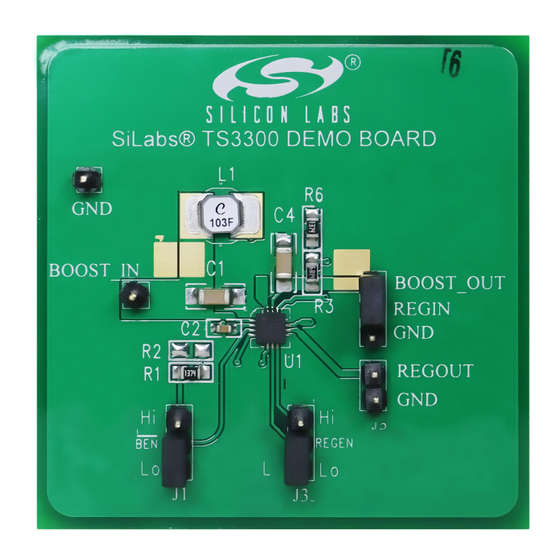
TS3300 Demo Board (Top View)
silabs.com | Smart. Connected. Energy-friendly.
™
feature to prevent the collapse of the input voltage
KEY FEATURES
• Boost Regulator
• Input Voltage: 0.6 V – 3 V
• Output Voltage: 3.6 V
• Shutdown Control Jumper
• Coilcraft 10 µH Inductor
(LPS4018-103ML)
• Resistor Pad Available for Anti-Crush
Voltage Setting
™
Rev. 1.1
Advertisement

Related Manuals for Silicon Laboratories TS3300


Summary of Contents for Silicon Laboratories TS3300
- Page 1 A pull-down resistor pad is available in order to set the anti-crush voltage. The TS3300 boost regulator is set to an output voltage of 3.6 V via a resistor divider cir- cuit. The TS3300 is fully specified over the –40°C to +85°C temperature range and is available in a low-profile, thermally-enhanced 16-pin 3×3 mm TQFN package with an ex-...
-
Page 2: Functional Description
Boost Regulator Output Voltage Setting The TS3300 boost regulator is set to an output voltage of 3 V via a resistor divider circuit, as shown in the figure below. Figure 1.1. Setting the Boost Output Voltage with a Voltage Divider The output feedback (BO FB) pin is 505 mV. -
Page 3: Quick-Start Procedure
UG188: TS3300 EVB User's Guide Quick-Start Procedure 2. Quick-Start Procedure 2.1 Required Equipment • TS3300 Demo Board • 1.2 V Battery or Power Supply • Two Digital Multimeters • Oscilloscope 2.2 Boost + Output Load Switch Configuration To evaluate the Boost + Output Load Switch configuration, the following steps should be performed: 1. - Page 4 UG188: TS3300 EVB User's Guide Schematics 3. Schematics Figure 3.1. TS3300 Demo Board Circuit Schematic silabs.com | Smart. Connected. Energy-friendly. Rev. 1.1 | 3...
- Page 5 UG188: TS3300 EVB User's Guide Schematics Figure 3.2. Top Silkscreen Figure 3.3. Top Layer #1 Figure 3.4. Top Layer #2 Figure 3.5. Top Layer #3 Figure 3.6. Bottom Layer Figure 3.7. Bottom Silkscreen silabs.com | Smart. Connected. Energy-friendly. Rev. 1.1 | 4...
-
Page 6: Ordering / Component List
UG188: TS3300 EVB User's Guide Ordering / Component List 4. Ordering / Component List Table 4.1. TS3300 Ordering Information Ordering Number Description TS3300DB TS3300 Demo Board Table 4.2. TS3300 Component List Designation Quantity Description 10 µH ±20% Shielded Inductor (4×4 mm) - Page 7 The products are not designed or authorized to be used within any Life Support System without the specific written consent of Silicon Laboratories. A "Life Support System" is any product or system intended to support or sustain life and/or health, which, if it fails, can be reasonably expected to result in significant personal injury or death.
Need help?
Do you have a question about the TS3300 and is the answer not in the manual?
Questions and answers