Table of Contents
Advertisement
Quick Links
CP2104 E
VALUATION
1. Kit Contents
The CP2104 Evaluation Kit contains the following items:
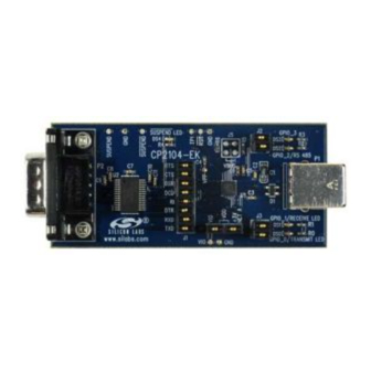
CP2104 Evaluation Board
RS232 Serial Cable
USB Cable
DVD
Quick Start Guide
2. Relevant Documentation
Application notes can be found on the Interface Application Notes page for all fixed-function devices:
www.silabs.com/interface-appnotes.
AN721: CP210x/CP211x Device Customization Guide — Customize the VID, PID, serial number, and
other parameters stored in the CP2104 one-time programmable ROM.
AN197: Serial Communications Guide for CP210x — Programming guide for using the Virtual COM Port
(VCP) drivers.
AN169: USBXpress Programmer's Guide — Programming guide for using the USBXpress drivers.
AN220: C8051F32x and CP210x USB Driver Customization — VCP or USBXpress driver customization
tool.
AN223: Port Configuration and GPIO for CP210x — Programming guide and DLL for runtime control of
the CP2104 GPIO pins.
AN571: CP210x Virtual COM Port Interface — USB interface details for CP210x devices.
3. Software Setup
The Software Development Kit (SDK) for the
installer can also be downloaded from the
Device Customization Utility (AN721)
Documentation — data sheet, application notes, user's guide, quick start guide, etc.
CP210x Virtual COM Port (VCP) Drivers
Software — Driver Customization Utility (AN220) and programming examples
The Windows installer should launch automatically after inserting the
appropriate directory on the
drivers to the system.
3.1. USBXpress Driver Development Kit
The Silicon Laboratories USBXpress
CP210x devices. No USB protocol or host device driver expertise is required. Instead, a simple, high-level Application
Program Interface (API) for the host software is used to provide complete USB connectivity. The USBXpress
Development Kit includes Windows device drivers, Windows device driver installer, host interface function library
(host API) provided in the form of a Windows Dynamic Link Library (DLL). See Application Note AN169, "USBXpress
Programmer's Guide" for detailed information on using the USBXpress drivers.
The USBXpress drivers are available here: www.silabs.com/usbxpress.
Click the USBXpress Development Kit link in the Download for Windows 2000/XP/Server 2003/Vista/Win7 section
to download the USBXpress drivers. Run the installer and follow the steps to install the software to the desired
Rev. 0.7 7/13
K
U
IT
CP2104
www.silabs.com/interface-software
to install the software package. Follow the instructions to install the SDK and
DVD
Development Kit provides a complete host software solution for interfacing to
®
Copyright © 2013 by Silicon Laboratories
C P 2 1 0 4 - E K
'
G
SER
S
UIDE
kit is included on the kit DVD. The latest version of this
website. This package includes:
. For Mac and Linux, browse to the
DVD
CP2104-EK
Advertisement
Table of Contents

Related Manuals for Silicon Laboratories CP2104


Summary of Contents for Silicon Laboratories CP2104
-
Page 1: Kit Contents
AN721: CP210x/CP211x Device Customization Guide — Customize the VID, PID, serial number, and other parameters stored in the CP2104 one-time programmable ROM. AN197: Serial Communications Guide for CP210x — Programming guide for using the Virtual COM Port (VCP) drivers. - Page 2 1. Connect one end of the USB cable to a USB Port on the PC. 2. Connect the other end of the USB cable to the USB connector on the CP2104 evaluation board. 3. Connect one end of the RS232 serial cable to the DB-9 connector on the CP2104 evaluation board.
- Page 3 5. CP2104 Software Interface If the Virtual COM Port drivers are used, the CP2104 will appear as a COM port in the Device Manager, as shown in Figure 2. The CP2104 will always use the lowest available COM port for operation. For instance, if COM ports 1 and 2 are in use by other peripherals and applications, the CP2104 will use COM 3.
-
Page 4: Evaluation Board
6.1. LED Headers (J2, J3) Connectors J2 and J3 are provided to allow access to the GPIO pins on the CP2104. Place shorting blocks on J2 and J3 to connect the GPIO pins to the four green LEDs DS0–DS3. These LEDs can be used to indicate active communications through the CP2104. - Page 5 VIO from an external source. Pins 3–4: Connects the main +3 V net to the CP2104 VDD (Pin 6). The main +3 V net powers the other components (four green LEDs and RS232 Sipex Part) on the evaluation board.
- Page 6 CP2104-EK 7. Schematic Rev. 0.7...
-
Page 7: Document Change List
Revision 0.1 to Revision 0.2 Updated "6.4. Power Connector (J4)" on page 5 to reflect the updated schematic. Updated J4 in Figure 4, “CP2104 Evaluation Board Schematic,” on page 6. Revision 0.2 to Revision 0.3 Updated "7. Schematic" on page 6. -
Page 8: Contact Information
Silicon Laboratories products are not designed, intended, or authorized for use in applications intended to support or sustain life, or for any other application in which the failure of the Silicon Laboratories product could create a situation where per- sonal injury or death may occur.
Need help?
Do you have a question about the CP2104 and is the answer not in the manual?
Questions and answers