Aastra 470 System Manual
As of r1.2
Hide thumbs
Also See for 470:
- System manual (304 pages) ,
- User manual (28 pages) ,
- Installation manual (22 pages)
Table of Contents
Advertisement
Quick Links
See also:
User Manual
Aastra Business Communication
Solution
Aastra 470 as of R1.2
System Manual
Platforms supported:
Aastra 470
This document contains information on the expansion
stages, system capacity, installation, configuration, run-
ning and maintenance of this Aastra communication
systems as well as their technical data.
It is intended for planners, installers and system manag-
ers of Aastra 400 communication systems.
syd-0337_en / 1.2 – R1.2 – © 11.2011
Advertisement
Table of Contents

Related Manuals for Aastra 470


Summary of Contents for Aastra 470
- Page 1 Aastra 470 This document contains information on the expansion stages, system capacity, installation, configuration, run- ning and maintenance of this Aastra communication systems as well as their technical data. It is intended for planners, installers and system manag- ers of Aastra 400 communication systems.
-
Page 2: Table Of Contents
2. 4 Aastra system phones and clients ....... .19 2. 5 Various phones and terminals. - Page 3 Fitting call charge modules........92 Aastra 470 as of R1.2...
- Page 4 4. 8. 1. 2 Aastra 5360/5361/5370/5380 ........137 4.
- Page 5 6. 2. 3 Software system Aastra DECT ........180 6.
- Page 6 Operating state of the Aastra DECT radio units....219 6. 5. 3. 5 Malfunction of the Aastra DECT radio unit ..... . 220 6. 5. 3. 6 Malfunctions of Aastra DECT cordless phones .
- Page 7 Aastra DECT Radio units ........
-
Page 8: Product And Safety Information
The expansion possibilities for the Aastra 470 communication server include an ap- plications server for unified communications and multimedia services, an FMC Controller for integrating mobile phones, an open interface for application devel- opers and a multitude of expansion cards and modules. - Page 9 • Make sure that the versions of the user documents comply with the software level of the Aastra 400 products used and that you have the latest editions. • Always read the user documents first before you install, configure and put a Aas- tra 400 communication solution into operation.
- Page 10 All parts and components of the Aastra 400 communication solution are manufac- tured in accordance with ISO 9001 quality guidelines. The relevant user information has been compiled with the utmost care. The functions of the Aastra 400 products have been tested and approved after comprehensive conformity tests. Nonethe- less errors cannot be entirely excluded.
-
Page 11: Safety Information
Hazard warnings are affixed whenever there is a risk that improper handling may put people at risk or cause damage to the Aastra 400 product. Please take note of these warnings and follow them at all times. Please also take note in particular of hazard warnings contained in the user information. -
Page 12: Data Protection
Protection against listening in and recording The Aastra 400 communication solution comprises features which allow calls to be monitored and recorded without the call parties noticing. Inform your customers that these features can only be used in compliance with national data protection provisions. -
Page 13: About This System Manual
The system functions and features, the DECT planning and the possibilities for networking several systems into a private net- work (PISN) or an Aastra Intelligent Net (AIN) are not part of this Manual; they are described in separate documents. - Page 14 Failure to observe information identified in this way can cause a defect to a module. Warning Failure to observe information identified in this way can lead to damage caused by electrostatic discharge. Aastra 470 as of R1.2 syd-0337/1.2 – R1.2 – 11.2011...
-
Page 15: About Aastra
North America, Europe and Africa as well as Internet Service Providers and distributors of renown. Aastra Technologies Limited, (TSX: “AAH”), is a leading company at the forefront of the enterprise communication market. Headquartered in Concord, Ontario, Can- ada, Aastra develops and delivers innovative communication products and appli- cations for businesses. -
Page 16: System Overview
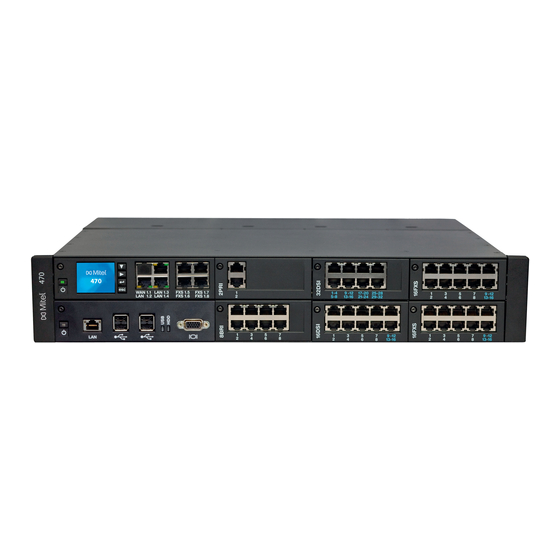
2. 2 Communication server Aastra 470 is the most powerful communication server in the Aastra 400 family. It is designed for installation in a 19” rack, but can also be set up on a flat surface. With the exception of the power supply and earthing, all the connections and con- trol elements are accessible from the front. -
Page 17: Positioning
Applications range from small businesses or branches to large companies at one or more locations. Up to 36 users can be operated on the Aastra 470 communication server without licensing. And with an expansion licence up to 400 users are possible. - Page 18 System Overview Aastra Intelligent Net (AIN) In an AIN several communication servers of the Aastra 400 family can be connected up to form a homogeneous communication system. The single systems are con- nected with one another via the IP network, thereby forming the nodes of the over- all AIN system One node acts as the Master and controls the other (satellite) nodes.
-
Page 19: Aastra System Phones And Clients
System Overview 2. 4 Aastra system phones and clients Aastra system phones stand out by virtue of their high level of user convenience and their attractive design. The broad range of products ensures there is a suitable model for every use. - Page 20 • Wall mounting possible when combined with expansion • Web configuration interface key module Note: The Aastra 5360ip IP system phone is supported as before. Tab. 4 IP system phones (softphones) and clients Product Main features • Autonomous, powerful, IP-based PC system phone with intuitive user interface •...
- Page 21 • All the system features can be used • FMC client for mobile phones (runs on various operating systems) • Integrates the mobile phone into the Aastra communication system • User is always reachable under the same call number (One Number con- cept) •...
- Page 22 The release for Aastra Blustar 8000i, Aastra 6735i and Aastra 6737i is independent from R1.2 and will be made later. Aastra 470 as of R1.2 syd-0337/1.2 – R1.2 – 11.2011...
- Page 23 System Overview Tab. 8 SIP phones of the Aastra 6750i series Additional model-specific fea- Product Principal common features tures • User-friendly registration, configu- Model-specific features include the ration and operation of system fea- resolution, the display type and tures through Aastra 400 integra- size, and the number of configura- tion.
-
Page 24: Various Phones And Terminals
2. 5 Various phones and terminals Thanks to the use of international standards other clients, terminals and phones, Aastra and third-party, can be connected and operated on the communication server: • SIP-based phones With the integrated SIP protocol SIP-based phones (softphones, hardphones) - or via an SIP access point also WLAN and DECT phones - can be connected to the communication server. -
Page 25: Applications And Application Interfaces
(incl. message attachment) • Partner program for integrating and certifying applications by other manufacturers • Pre-installed on the applications card (CPU2) of the Aastra 470 commu- nication server • Unified & collaborative communication application with extensive mul- timedia services •... - Page 26 Tab. 11 Planning and configuration applications Application Main features • Web-based planning application for Aastra communication platforms • Uses project data to calculate the necessary communication server com- plete with terminals, interface cards, modules and licences Aastra Plan • Country-specific adaptations possible for accessories •...
-
Page 27: Application Interfaces
Open Interfaces Platform (OIP). This open interface allows the applications to be deeply integrated with telephony. Third-party applications can also be inte- grated on systems of the Aastra 400 series via different interfaces without OIP. 2. 6. 2. 1... -
Page 28: Message And Alarm Systems
OIP on several communication servers An OIP server can also be used as in an Aastra Intelligent Net. To do so, it will be linked to the Master. It is then possible for instance to obtain network-wide call log-... -
Page 29: Cti - Computer Telephony Integration
In addition the duration of the tone as well as its volume and melody can be freely defined by the user for each alarm. The cordless DECT phone Aastra 630d is specially designed for applications in the security and alarming sector. Besides a special alarm button it also features a man- down alarm, a no-movement alarm and an escape alarm. - Page 30 CTI workstations and is easily implemented. Connection via Ethernet Aastra 400 supports First-Party CTI on all system phones via the Ethernet interface. For this purpose the First-Party TAPI Service Provider (AIF-TSP) is required. Application example •...
-
Page 31: Isdn Interface
2. 6. 2. 8 Hotel Management Systems A PC can be connected via Ethernet to run functions in Aastra 400 using command language. A special command set is available for communicating with hotel man- agement systems. These commands can then be used to carry out user-specific polling operations (e.g. -
Page 32: Connection Options
Fixed Mobile Convergence Controller Monitor Aastra Mobile Client Plus Ethernet Applications server Keyboard, mouse, etc. Ethernet Message and alarm systems Hotel Management Systems Fig. 4 Overview of interfaces with possible terminal equipment Aastra 470 as of R1.2 syd-0337/1.2 – R1.2 – 11.2011... -
Page 33: Expansion Stages And System Capacity
Fig. 5 Overview of the expansion possibilities The basic system Aastra 470 can be expanded not just with interface cards and sys- tem modules but also with an applications card (CPU2). The applications card is supplied with preinstalled operating system, unified communications and multi- media applications. -
Page 34: Basic System
Expansion Stages and System Capacity The Aastra 470 basic system has an integrated fan. The operating reliability of the communication server can be increased by fitting an optional redundant fan unit. It is powered by an internal power supply unit (PSU2U). An external auxiliary power supply unit (APS2) is required for expansions involving a large number of power- consuming terminals. - Page 35 Redundant fan unit as an option (RFU) Backplane (BP2U) Call Manager card (CPU1) Plug-in connections for the interface cards Fig. 7 Aastra 470 basic system fitted with a redundant fan unit Aastra 470 as of R1.2 syd-0337/1.2 – R1.2 – 11.2011...
-
Page 36: Interfaces, Display And Control Elements
Earth connection Mains socket for 115/230 V power supply input 115/230 V voltage converter Socket for auxiliary power supply unit APS2 1 fewer slot if CPU2 application card is fitted Aastra 470 as of R1.2 syd-0337/1.2 – R1.2 – 11.2011... - Page 37 The figure below shows the positions of the interfaces and of the display and con- trol elements on the call manager card. [10] Fig. 9 Interfaces, display and control elements of the call manager card CPU1 Aastra 470 as of R1.2 syd-0337/1.2 – R1.2 – 11.2011...
-
Page 38: Power Supplies
Power supplies Internal power supply unit PSU2U The Aastra 470 communication server is powered as standard directly with a mains cable. The voltage converter needs to be set to the correct position to match the mains power (230 VAC or 115 VAC) (see also "Powering the communication server",... - Page 39 Mains power 115/230 VAC Fig. 10 Overview of the Aastra 470 power supply concept Notes – It is also possible to operate the communication server with the exter- nal power supply unit APS2 only In this case redundancy operation is of course no longer possible.
-
Page 40: Ethernet Concept
3. 2. 3 Ethernet concept Aastra 470 provides three GBit Ethernet interfaces, which are routed to the front panel of the call manager card. They are used to connect to the customer’s data network (LAN) and e. g. the IP connection with an SIP provider. The socket marked "WAN"... -
Page 41: Dsp Resources
Voice memory capacity approx. 20 minutes, no e-mail notification in the event of new voice messages. With a licence, the basic voice mail can be expanded with the Auto Attendant function. Licences required Aastra 470 as of R1.2 syd-0337/1.2 – R1.2 – 11.2011... -
Page 42: Expansion With Cards And Modules
DSP modules. Some of these functions are subject to a licence. 3. 3 Expansion with cards and modules An Aastra 470 basic system can be individually expanded using interface cards, sys- tem modules and an application card. The number and position of the available slots are described in the chapter "Interfaces, display and control elements",... - Page 43 Voice Mail System via an SIP network interface. In an AIN VoIP channels are also used for call connections between the nodes (see Fig. 13 for an overview). The number of configurable VoIP channels depends on Aastra 470 as of R1.2 syd-0337/1.2 – R1.2 – 11.2011...
- Page 44 DSP chip (see "Configuration of DSP chips", page 47). Note With the Aastra 470 communications server G.711 voice channels are always used for voice mail and Auto Attendant. The Voice mail mode parameter cannot therefore be altered for this system. •...
- Page 45 SIP Access Point Internal voice mail system WiFi mobile phone via Internal announcement service AMC-Controller Music on hold External via SIP provider Satellit Fig. 13 Overview of the use of VoIP channels Aastra 470 as of R1.2 syd-0337/1.2 – R1.2 – 11.2011...
- Page 46 Auto Attendant, depending on where they happen to be required. After a first start the voice channels are not reserved and can therefore be used for voice mail and Auto Attendant. Aastra 470 as of R1.2 syd-0337/1.2 – R1.2 – 11.2011...
- Page 47 G.711 VoIP channels of the configurable DSP chip on processor card CPU1 can be combined with G.711 VoIP channels of DSP modules. Although no longer available, the module is still supported. Aastra 470 as of R1.2 syd-0337/1.2 – R1.2 – 11.2011...
-
Page 48: Ip Media Modules
IP media modules can be fitted both to the processor card CPU1 (see Fig. 9, page 37) and to the 1PRI and 2PRI trunk cards (see Fig. 16, page 50). The modules stackable. Aastra 470 as of R1.2 syd-0337/1.2 – R1.2 – 11.2011... -
Page 49: Call Charge Modules
Number of modules per Number of modules per Type 4FXO trunk card 8FXO trunk card 4TAX – 8TAX – The availability of the call charge modules depends on the sales chan- nel. Aastra 470 as of R1.2 syd-0337/1.2 – R1.2 – 11.2011... -
Page 50: Interface Cards
The splits can also be made elsewhere, e. g. using system cables available sepa- rately (see "Prefabricated system cable 4 x RJ45", page 95). Fig. 16 Example of an interface card (2PRI with 2 IP media modules fitted) Aastra 470 as of R1.2 syd-0337/1.2 – R1.2 – 11.2011... -
Page 51: Trunk Cards
• 1 call charge module can be fitted for 8 ports 1 fewer card if CPU2 application card is fitted The availability of the FXO trunk cards depends on the sales channel. Aastra 470 as of R1.2 syd-0337/1.2 – R1.2 – 11.2011... -
Page 52: Terminal Cards
• All interfaces configurable to BRI-T 4 × BRI-S 8BRI • Four fixed BRI-T interfaces • 4 BRI-S interfaces configurable to BRI-T 1 fewer card if CPU2 application card is fitted Aastra 470 as of R1.2 syd-0337/1.2 – R1.2 – 11.2011... -
Page 53: Application Card Cpu2
Ethernet and the backplane, which means that the Ethernet interface on the front panel is not required. The Windows Server 2008 embedded operating system and the Aastra applica- tions Open Interfaces Platform (OIP) and Telephony Web Portal (TWP) are prein- stalled on the application card’s standard PC. -
Page 54: System Capacity
Note: The values in the following three tables relate to a communication server with an Aastra 470 Expansion expansion licence. Without this licence the system is limited to the first 36 users in the numbering plan, which means many values in the table are not valid. - Page 55 User per announcement / message group Data service tables User accounts for User Access Control Authorization profiles for user accounts Log entries per user account First-party CTI users via LAN Aastra 470 as of R1.2 syd-0337/1.2 – R1.2 – 11.2011...
- Page 56 Busy lamp field buttons on Aastra SIP phones in total 1000 1000 Busy lamp field buttons per Aastra SIP phone Same users on busy lamp field buttons on Aastra SIP phones Freely configurable keys 5000 5000 Expansion key modules on DSI terminals...
-
Page 57: Terminals
Aastra 620d Aastra 630d GAP terminals Terminals on LAN interfaces (total) IP terminals Aastra 2380ip Aastra 5360ip Aastra 5361ip Aastra 5370ip Aastra 5380ip IP operator consoles Office 1560IP Aastra 5380ip Aastra 470 as of R1.2 syd-0337/1.2 – R1.2 – 11.2011... - Page 58 The release for this product is independent from R1.2 and will be made later. Maximum of 2 simultaneous call connections. Transmission with the T.38 protocol is recommended for Fax over IP. The corresponding DSP resources need to be allocated. Aastra 470 as of R1.2 syd-0337/1.2 – R1.2 – 11.2011...
-
Page 59: Terminal And Network Interfaces
Use of the call manager software requires a licence. Additional licences are required in order to use a number of enhanced functions and protocols, to enable voice channels or to operate certain terminals. The Aastra Plan application automatically plans the necessary licences, which are then enabled on the communication server using a licence code. - Page 60 Tab. 30, page Aastra Intelligent Net In an AIN with an Aastra 470 as Master and more than 36 users, an Aastra 470 Expansion licence is required only for the Master. The Aastra 470 satellites do not need a licence, even if they have more than 36 users (except of course for offline operations lasting more than 2 hours).
- Page 61 To operate Aastra SIP terminals of the Aastra 6700i family, for cordless terminals logged on via Aastra SIP DECT or Aastra SIP WLAN base stations, and for SIP us- ers for the TWP application (Telephony Web Portal), one licence is required per terminal or user.
- Page 62 IP terminals, SIP terminals, SIP access channels or to op- erate an Aastra Intelligent Net. High voice data compression is possible with the standard VoIP channels (G.729). One voice channel is activated with each li- cence.
- Page 63 • Aastra 2380ip Softphones One licence per terminal is required to operate the IP softphones Aastra 2380ip. The licences are needed to register the terminals on the system. • Aastra Dialog 4200 Phones One licence per phone is required to operate Dialog 4220, Dialog 4222 and Dialog 4223 digital phones.
- Page 64 Requirement: The DSP resources on each node must be available and allocated accordingly. Aastra 470 as of R1.2 syd-0337/1.2 – R1.2 – 11.2011...
- Page 65 (see Ethernet interface "System capacity", page ATAS Interface Use of the ATAS inter- unavailable enabled per node face ATASpro Interface Use of the ATASpro unavailable enabled per node interface Aastra 470 as of R1.2 syd-0337/1.2 – R1.2 – 11.2011...
- Page 66 In the AIN, phones opened in AMS phone per licence and only on the with Aastra Mobile Cli- the possibility of activat- Master; other- ing an Aastra Mobile Cli- wise per node. Aastra 470 as of R1.2 syd-0337/1.2 – R1.2 – 11.2011...
- Page 67 Master; other- wise per node. Silent Intrusion Use of the Silent intru- unavailable enabled In the AIN, sion feature only on the Master; other- wise per node. Aastra 470 as of R1.2 syd-0337/1.2 – R1.2 – 11.2011...
- Page 68 – SIP Access Channels, unlimited – VoIP Channels for Standard Media Switch, unlimited – Mobile Phone Extension, unlimited – Aastra Dialog 4200 Phones, unlimited – Aastra 5300ip Phones, unlimited – Aastra 2380ip Softphones, unlimited To ensure a longer-lasting offline operation the necessary licences must also be purchased for the satellites.
- Page 69 • Voice mail functions are out of service (no routing to voice mail). • The announcement service is out of operation. Restrictions in an Aastra Intelligent Net In an AIN, the satellites carry out a restart every four hours. Trial licences Trial licences are available for some functions.
-
Page 70: Power Supply Capacity
The maximum number of terminals connected to the system can be limited by the supply power available for terminals. It is also important to take note of the maxi- mum load per terminal interface. Aastra 470 as of R1.2 syd-0337/1.2 – R1.2 – 11.2011... -
Page 71: Supply Power Available For Terminals
(P ) from the power specifications in Tab. 32, page 71 total Tab. 33 Power requirements of hardware components Aastra 470 Designation Output P [W] Basic system with CPU1 call manager card Interface card 1PRI Interface card 2PRI... - Page 72 Aastra 5361 DSI-AD2 interface Aastra 5370 DSI-AD2 interface Aastra 5380 DSI-AD2 interface Aastra 5370, Aastra 5380 with power supply unit DSI-AD2 interface Expansion key module Aastra M530 Aastra 5370 Expansion key module Aastra M530 Aastra 5380 Expansion key module Aastra M535...
- Page 73 The value applies to phones with hardware version "-2". The value for phones with hardware version "-1" is 60 mW lower. The value depends greatly on the terminal type. With the planning application Aastra Plan the power supply available for terminals is checked automatically. Overload shutdown...
-
Page 74: Power Supply Per Interface
• Terminals used incl. auxiliary devices • Bus configuration • Line length and conductor cross-section For information on the calculations refer to "Terminal interfaces", page 109. Aastra 470 as of R1.2 syd-0337/1.2 – R1.2 – 11.2011... -
Page 75: Installation
Installation Installation This Chapter tells you the ways in which Aastra 470 can be installed and the conditions to be observed. It also includes the mounting into a 19” rack, the correct way to connect the earthing, and the power supply. Other topics in this chapter include how to fit system modules and interface cards. -
Page 76: Fitting The Communication Server
Installation 4. 2 Fitting the communication server The Aastra 470 communication server is designed for installation in a 19” rack (2 height units). The communication server can also simply be placed on a flat sur- face. Wall-mounting is not allowed. -
Page 77: Safety Regulations
Always touch the earthed metal case of the communication server before carrying out work inside the housing. This also applies to interface cards and system modules that are no longer packed inside the ESD protective wrapping. Aastra 470 as of R1.2 syd-0337/1.2 – R1.2 – 11.2011... -
Page 78: Flow Of Hot Air
4. 2. 4 Flow of hot air The Aastra 470 communications server ships with a fan already pre-installed. The housing is designed so the air flow is first guided at two levels over the processor cards and the interface cards, then passes through cutouts in the backplane, ab- sorbs the heat from the power supply unit, and exits the housing through the fan aperture. -
Page 79: Desktop Installation
4. 2. 6 Rack-mounting The rack mounting of the Aastra 470 communication server allows it to be installed horizontally in a 19” rack. Be sure to observe the following: • The communication server takes up the space of 2 height units (units) inside the 19”... -
Page 80: Fitting An Additional Fan
Fans have a limited service life. So if a fan fails become of age (> approx. 5 years) it is advisable to replace both fans as a precautionary measure. Materials required: • Aastra 470 additional fan premounted on fastening frame • Set of screws for additional fan • Screwdriver To install the additional fan proceed as follows: 1. -
Page 81: Earthing And Protecting The Communication Server
Standard fan Redundant fan unit Fastening frame Fig. 20 Fitting the additional fan in Aastra 470 4. 3 Earthing and protecting the communication server The protective earth and equipotential bonding are important integral parts of the safety concept: Standard EN 60950 relevant to safety matters stipulates protective earthing. -
Page 82: Connecting The Earthing Wire
The communication server’s earthing connection is located on the rear panel of the communications server next to the mains power socket. The earthing wire is se- cured using a screw and a spring washer. Fig. 21 Earthing connection Aastra 470 as of R1.2 syd-0337/1.2 – R1.2 – 11.2011... - Page 83 (main) distribution frame. The cables should be kept as short as possible and laid out in parallel. Aastra 470 as of R1.2 syd-0337/1.2 – R1.2 – 11.2011...
-
Page 84: Connecting The Cable Screening
(UPS) must be used. Hazard: Hazard due to heat generation in the event of short-circuits. The mains power supply connection must be protected with 16 A maxi- mum. Aastra 470 as of R1.2 syd-0337/1.2 – R1.2 – 11.2011... -
Page 85: Internal Power Supply Unit
Suitable for a typical system configuration external auxiliary power sup- with power supply redundancy ply unit External auxiliary power sup- 240 Watt Minor heat generation inside the Aastra ply unit only 470 housing Internal power supply unit + 360 Watt Suitable for maximum power require-... -
Page 86: External Auxiliary Power Supply Unit
6 screws. If a fan-out-panel (FOP) is already fitted, the auxiliary power supply can be installed behind the connection panel. The following diagram shows the fan-out-panel from below with the auxiliary power supply fitted. Aastra 470 as of R1.2 syd-0337/1.2 – R1.2 – 11.2011... -
Page 87: Uninterruptible Power Supply (Ups)
It is important to note that the battery must never be allowed to become completely discharged and that in typical conditions only ap- prox. 60% of the maximum power requirements is needed. Aastra 470 as of R1.2 syd-0337/1.2 – R1.2 – 11.2011... -
Page 88: Equipping The Basic System
230. 4. 5 Equipping the Basic System For individual expansion the Aastra 470 basic system can be fitted with interface cards, system modules and an application card. An overview can be found in the Chapter "Expansion Stages and System Capacity", page 4. -
Page 89: Fitting Application Card Cpu2
With system modules a distinction is made between modules expandable as an op- tion (DSP modules, IP media modules, Call charge modules) and mandatory mod- ules (RAM module). The system cards (Flash card, EIM card) are always required. Aastra 470 as of R1.2 syd-0337/1.2 – R1.2 – 11.2011... -
Page 90: Fitting Dsp Modules
4. The spacer sleeve for the lower module is already premounted on the processor card. For the upper DSP module screw the spacer sleeve supplied with the mod- ule into place. Aastra 470 as of R1.2 syd-0337/1.2 – R1.2 – 11.2011... -
Page 91: Fitting Ip Media Modules
8. Restart the call manager by pressing the On/Off button on the call manager card. Proceed accordingly to fit one or two IP Media modules to a PRI trunk card. Aastra 470 as of R1.2 syd-0337/1.2 – R1.2 – 11.2011... -
Page 92: Fitting Call Charge Modules
7. Use the screw to secure the FXO card back into its slot. 8. Restart the call manager by pressing the On/Off button on the call manager card. Aastra 470 as of R1.2 syd-0337/1.2 – R1.2 – 11.2011... -
Page 93: Component Mounting Rules
– The interfaces are enabled in accordance with their designation, starting with the lower designations. This means that the terminal interfaces on the proces- sor card are always enabled before those on the interface cards. Aastra 470 as of R1.2 syd-0337/1.2 – R1.2 – 11.2011... -
Page 94: Connecting The Communication Server
There are two possibilities for connecting the communication server indirectly to the telephone network and terminal-side cabling: • Connection via main distribution board • Connection to a universal building cable installation (UBC) Aastra 470 as of R1.2 syd-0337/1.2 – R1.2 – 11.2011... -
Page 95: Connection Via Main Distribution Board
With terminal cards with 16 or more interfaces some or all of the RJ45 sockets are assigned four-fold on the front panel of the Aastra 470. With this cable they can be connected without the use of a fan-out-panel (FOP). The cable is 6 m long and at one extremity has four RJ45 connectors on which all the pins are wired. - Page 96 PRI primary rate interface", page 104 "Connection of Ether- net interfaces", page 133). Use standard commercial connecting cables not just for the PRI and Eth- ernet interfaces but also for connecting the BRI-T interfaces. Aastra 470 as of R1.2 syd-0337/1.2 – R1.2 – 11.2011...
- Page 97 – turquoise – violet – – blue – turquoise – violet – – orange – turquoise – violet – Ansicht A Ansicht B Fig. 31 Pin numbering, RJ45 connector Aastra 470 as of R1.2 syd-0337/1.2 – R1.2 – 11.2011...
-
Page 98: Connection To A Universal Building Cable Installation (Ubc)
Connecting to a UBC via a (main) distribution board (example) User Patch panel Telephone User side Telephone Exchange side Exchange Fig. 33 Connecting to a UBC via wiring centre (example) Aastra 470 as of R1.2 syd-0337/1.2 – R1.2 – 11.2011... -
Page 99: Cabling Interfaces
A port address is always of the type x.y. x is the number of the card slot, and y, the port number. The slot numbering starts with 1 and ends with 8 (see "Number of the Aastra 470 slots", page 88). -
Page 100: Network Interfaces
Equipping the system with interface cards provides the necessary network inter- faces. With the exception of the Ethernet interface, which also represents a network interface via SIP access, there are no network interfaces on the Aastra 470 commu- nication server. - Page 101 Basic access in the private leased-line network BRI-T BRI-S Copper line extern PINX 1 PINX 2 max. 1,000 m Fig. 37 BRI-S basic rate interface , networked with copper line external Aastra 470 as of R1.2 syd-0337/1.2 – R1.2 – 11.2011...
- Page 102 PINX 2 signal, basic rate inter- Cable cores Network Cable cores basic rate inter- face BRI-T face BRI-T See also Chapter "Connections with basic accesses" in the PISN/QSIG Networking System Manual. Aastra 470 as of R1.2 syd-0337/1.2 – R1.2 – 11.2011...
-
Page 103: Primary Rate Interface Pri
< 125 Ω (100 kHz), < 115 Ω (1 MHz) Characteristic impedance Wave attenuation < 6 dB/km (100 kHz), < 26 dB/km (1 MHz) Near / crosstalk attenuation > 54 dB/100 m (1 kHz to 1 MHz) Aastra 470 as of R1.2 syd-0337/1.2 – R1.2 – 11.2011... - Page 104 Primary rate access in the private leased-line network 4-wire Copper line PINX 1 PINX 2 max. 200 m 4-wire Copper line PINX 1 PINX 2 max. 200 m Fig. 41 Primary rate access, networked with copper line Aastra 470 as of R1.2 syd-0337/1.2 – R1.2 – 11.2011...
- Page 105 — — — — — — — — Transmission facilities PINX 1 PINX 2 max. max. 200 m 200 m Fig. 42 Primary rate interface, networked with transmission equipment Aastra 470 as of R1.2 syd-0337/1.2 – R1.2 – 11.2011...
- Page 106 — — — — — — Leased-line or dial-up PINX 1 PINX 2 connection Mains power Mains power Fig. 43 Primary rate access PRI, networked with leased-line or dial-up connection Aastra 470 as of R1.2 syd-0337/1.2 – R1.2 – 11.2011...
-
Page 107: Fxo Network Interfaces
92). In a direct connection the RJ45 connector is connected directly to the trunk cable using a crimp clip. With an indirection connection you need to observe the cable requirements. Aastra 470 as of R1.2 syd-0337/1.2 – R1.2 – 11.2011... - Page 108 Cable requirements for FXO network interface Core pairs × cores 1 × 2 Stranded not required Wire diameter, core 0.4 … 0.8 mm Screening not required max. 2 × 250 Ω Resistance Aastra 470 as of R1.2 syd-0337/1.2 – R1.2 – 11.2011...
-
Page 109: Terminal Interfaces
Connection of individually assigned DSI terminal interface Communication server Cable cores Connection socket Socket DSI signal DSI signal Socket – – – – – – – – – – – – Aastra 470 as of R1.2 syd-0337/1.2 – R1.2 – 11.2011... - Page 110 Socket DSI signal DSI signal Socket – – – – – – – – – – – – – – – – – – – – – – – – Aastra 470 as of R1.2 syd-0337/1.2 – R1.2 – 11.2011...
- Page 111 (protocol) on the DSI bus can be se- lected under CM_2.1.1 in AMS: • DSI-AD2: For system phones of the Aastra 5300 series and for SB-4+ and SB-8 DECT radio units. • DSI-DASL: For system phones of the Dialog 4200 series.
- Page 112 Although no longer available, the phone is still supported. The value can increase to approx. 600 mW if the power available at the DSI-AD2 bus allows it. An Aastra M535 always requires a power supply unit Aastra 470 as of R1.2...
- Page 113 DSI-AD2 bus is not the same in every case: Power available A: • Applies to all the system phones of the Aastra 5300 series and the Office series. • Applies to the SB-4+/SB-8 DECT radio units with hardware version "-1".
- Page 114 Notes – If another system phone is operated on the DSI-AD2 bus in addition to an Aastra 5361, Aastra 5370 or Aastra 5380, at least one phone must be powered by a local power supply unit. – An Aastra 5370 or Aastra 5380 with an Aastra M535 expansion key module always requires a power supply unit.
- Page 115 – Depending on the power available based on the line length on the DSI-AD2 bus the ringing and hands-free volume decreases accord- ingly. – The backlighting of the Aastra 5380 display is brighter if the phone is powered by a power supply unit. Rating examples...
- Page 116 Note: max. 25 m can be crossed unstranded. (CH: Applies also to cable type G51) Installation rules • If an Aastra DECT radio unit is used, do not connect any other system phone to the same DSI bus. • If...
-
Page 117: Bri-S Terminal Interfaces
Installation Terminals The following system terminals can be operated on the DSI-AD2 bus: • System phones of the Aastra 5300 series • Aastra DECT Radio units The system phones on an DSI-AD2 bus are addressed via a single-digit terminal se- lection digit (TSD). - Page 118 The maximum number of terminals per S bus depends on the power requirements of the terminals (see "Restrictions", page 119). 8. Connection point Communica- 2 x 100 Ω tion server max. 150 m Fig. 50 S bus, short Aastra 470 as of R1.2 syd-0337/1.2 – R1.2 – 11.2011...
- Page 119 Tab. 60 Power balance on the S bus Power available [W] S bus short S bus, long These values are based on a wire diameter of 0.5 mm. Aastra 470 as of R1.2 syd-0337/1.2 – R1.2 – 11.2011...
- Page 120 The number of terminals is the sum of the power requirements of the individual terminals and the power available on the S bus. Connection sockets Fig. 54 RJ45 connection, single socket Ω Fig. 55 RJ45 connection, double socket Aastra 470 as of R1.2 syd-0337/1.2 – R1.2 – 11.2011...
- Page 121 • ISDN Terminal Adapter • PC with ISDN card • Group 4 fax machines , etc. Two call connections are possible simultaneously for each S bus. Not possible within an AIN Aastra 470 as of R1.2 syd-0337/1.2 – R1.2 – 11.2011...
-
Page 122: Fxs Terminal Interfaces
Connection of individually assigned FXS terminal interface Communication server Cable cores Connection socket Analogue Analogue Socket Socket signal signal – – – – – – – – – – – – Aastra 470 as of R1.2 syd-0337/1.2 – R1.2 – 11.2011... - Page 123 Analogue Analogue Socket Socket signal signal – – – – – – – – – – – – – – – – – – – – – – – – Aastra 470 as of R1.2 syd-0337/1.2 – R1.2 – 11.2011...
- Page 124 • Radio units for cordless phones • Group 3 fax machines • Answering machines • Modem Transmission with the T.38 protocol is recommended for Fax over IP. The corresponding DSP resources need to be allocated. Aastra 470 as of R1.2 syd-0337/1.2 – R1.2 – 11.2011...
- Page 125 In this mode two-wire door intercoms with DTMF control functions can be con- nected. The no-load voltage in this mode is 24 VDC. The loop current is limited to 25 mA. Aastra 470 as of R1.2 syd-0337/1.2 – R1.2 – 11.2011...
- Page 126 "Music on hold" and then to store it as a wave file. line out FXS interface Fig. 59 Connection for FXS mode: External audio source Aastra 470 as of R1.2 syd-0337/1.2 – R1.2 – 11.2011...
- Page 127 There are no special requirements for the cables. Warning Control outputs must have a floating connection. max. 25mA 24 VDC FXS interface Fig. 60 Connection for FXS mode: Control output Aastra 470 as of R1.2 syd-0337/1.2 – R1.2 – 11.2011...
- Page 128 • The same switch group can only be switched by the 2 assigned control inputs. • Control of the switch groups using the control inputs takes priority over control using function codes. Aastra 470 as of R1.2 syd-0337/1.2 – R1.2 – 11.2011...
-
Page 129: Fan-Out Panel Fop
The fan-out panel (FOP) takes up the space of one height unit in a rack and can be fitted directly above or below the communication server. Fan-out panels can also be offset, e. g. as floor distributors. Fig. 63 Fan-out panel FOP Aastra 470 as of R1.2 syd-0337/1.2 – R1.2 – 11.2011... - Page 130 229). The internal wiring of the fan-out panel is shown in the table below. The wiring is shown for sockets 1 - 4. Sockets 5 - 8 are wired accordingly. Aastra 470 as of R1.2 syd-0337/1.2 – R1.2 – 11.2011...
- Page 131 If analogue trunk lines (FXO interfaces) are to be routed via the fan-out panel FOP, for safety reasons the fan-out panel must be connected to the protective earth (see Fig. 65, page 132). Aastra 470 as of R1.2 syd-0337/1.2 – R1.2 – 11.2011...
-
Page 132: Ethernet Interfaces
4. 7. 5 Ethernet interfaces The communication server Aastra 470 has a Gbit Ethernet switch on the call man- ager card. Three LAN interfaces are routed to the front panel of the call manager card and labelled accordingly. The RJ45 sockets are highlighted in colour in the fig- ure below. - Page 133 DHCP server fails, the communication server deactivates DHCP tem- porarily and can be accessed via the static default value address. The communica- tion server is then accessible with a direct connection via the IP address. Aastra 470 as of R1.2 syd-0337/1.2 – R1.2 – 11.2011...
- Page 134 Port has a connection with the network flashing 100 Mbit/s Port is receiving or sending data 1 Gbit/s Port has a connection with the network flashing 1 Gbit/s Port is receiving or sending data Aastra 470 as of R1.2 syd-0337/1.2 – R1.2 – 11.2011...
- Page 135 Use commercial Cat. 5 cable, or choose a cable type with the following characteris- tics: Tab. 74 Requirements for an Ethernet cable Core pairs × cores 4 × 2 Stranded Wire diameter, core 0.4...0.6 mm Screening Category Cat. 5 minimum Aastra 470 as of R1.2 syd-0337/1.2 – R1.2 – 11.2011...
-
Page 136: Installing, Powering And Connecting Terminals
– A terminal has been created at the connected port, but the address selection switch is incorrectly set. – No terminal has yet been created at the connected port. Aastra 470 as of R1.2 syd-0337/1.2 – R1.2 – 11.2011... -
Page 137: Aastra 5360/5361/5370/5380
These IP system phones can be both desktop-mounted and wall-mounted. Mounting the phone The following points are described in detail in the User’s Guides for Aastra 5360/ 5361/5370/5380: • Set-up as a desk phone (choice of two different set-up angles) •... - Page 138 To prevent any damage to the phone, always disconnect the phone from the power supply first before connecting a headset to DHSG standard. Mounting the Bluetooth module The Aastra 5380 can also be equipped with a Bluetooth module as an option. To in- stall (see Fig. 68), proceed as follows: Fig.
- Page 139 (see ➃). Powering the phone The Aastra 5360, Aastra 5361 Aastra 5370 and Aastra 5380 system phones are nor- mally powered via the DSI bus. However there are several reasons that require pow- ering with a plug-in power supply: •...
-
Page 140: Office 25, Office 35, And Office 45/45Pro
Connecting the expansion key module or the alphanumerical keyboard The connection of the expansion key modules and the alphanumerical keyboard to Office 35 and Office 45 is described in the relevant operating instructions. Aastra 470 as of R1.2 syd-0337/1.2 – R1.2 – 11.2011... - Page 141 Installation Fig. 69 Wall mounting of Office 25 and Office 35 Aastra 470 as of R1.2 syd-0337/1.2 – R1.2 – 11.2011...
-
Page 142: Office 10
Fig. 70 Set the DSI bus address Note: Make sure the TSD (address switch) is pushed in as far as the stop or the switchover will not function correctly. Aastra 470 as of R1.2 syd-0337/1.2 – R1.2 – 11.2011... -
Page 143: Dect Radio Units And Cordless Phones
Office 135 can be linked using connecting strips. However, operating several phones on interconnected charging bays can lead to malfunc- tions.) • Minimum distance between charging bays with cordless phones on-hook for fault-free operation: 0.2 m. Aastra 470 as of R1.2 syd-0337/1.2 – R1.2 – 11.2011... -
Page 144: Installing The Radio Units
Office 135 charging bay. ø screw : 4 mm Mounting bracket All dimensions in mm Fig. 71 Dimensional drawing for wall-mounting the mounting bracket Aastra 470 as of R1.2 syd-0337/1.2 – R1.2 – 11.2011... - Page 145 Installation distances Connecting the radio unit 230 VAC (optional) DSI interface Socket 1 Socket 2 Sockets, external antennas ( SB-8ANT only) Fig. 73 Underside of the radio units with connection points Aastra 470 as of R1.2 syd-0337/1.2 – R1.2 – 11.2011...
-
Page 146: Ip System Phones
IP system phones The installation, powering and connection of the IP system phones Aastra 5360ip, Aastra 5361ip, Aastra 5370ip, Aastra 5380ip and Aastra 2380ip are described in the System Manual "Aastra Intelligent Net (AIN) and IP system phones". 4. 8. 4... -
Page 147: Aastra Sip And Standard Sip Phones
4. 8. 5 Aastra SIP and standard SIP phones The registration of SIP system phones of the Aastra 6700i series, other Aastra SIP terminals and SIP terminals by other manufacturers as internal users is described in the "SIP and SIP terminals" System Manual. -
Page 148: Configuration
5. 1 AMS Configuration Tool The Aastra Management Suite (AMS) is a software package used for the configura- tion and monitoring of a single system or an entire network. The configuration can be prepared offline and locally or remotely loaded to the configuration server. Re- mote access means that changes and expansions can be carried out independently of time and location, and is used for the remote maintenance of the system. -
Page 149: Ams Manager
(Exception: SEM is called up via the Windows Start menu or by means of the icon in the Windows taskbar). The following table shows which Managers are password protected and which are available offline or online. Aastra 470 as of R1.2 syd-0337/1.2 – R1.2 – 11.2011... -
Page 150: Auxiliary Applications
System Search is a help tool for detecting com- munication servers of the Aastra 400 series in the IP network. System Search finds all individual communication servers connected to the IP network, provided they are in the same subnetwork as the PC with AMS and have at least SW version I7. - Page 151 The WebAdmin is included in the file system of each communication server of the Aastra 400 family and does not have to be installed separately. Note: The web based administration enables two users to access the same com- munication server simultaneously.
-
Page 152: Access Types
External dial-up access via dial-in node (only in AIN) External dial-up access via ISDN connection via a BRI-T network interface Fig. 74 Overview of the access types See also: Detailed information can be found in the AMS Help. Aastra 470 as of R1.2 syd-0337/1.2 – R1.2 – 11.2011... -
Page 153: User Access Control
• SystemUserInterface The authorization profiles are assigned administration rights and interface user rights. The allocation of existing authorization profiles can be transferred to other authorization profiles using "Copy & Paste". Aastra 470 as of R1.2 syd-0337/1.2 – R1.2 – 11.2011... -
Page 154: Administration Rights
(announcement service), and to record and delete audio data for the Music on hold function. • AMS-Authorization level Determines the authorization level for handling, accessing and editing the con- figuration data via AMS, and the software upload authorizations. Aastra 470 as of R1.2 syd-0337/1.2 – R1.2 – 11.2011... -
Page 155: Interface Access
• Third-party CTI Allows third-party applications to communicate with the PBX via the IP network by means of the CTI interface. This authorization is not intended for individual persons. Aastra 470 as of R1.2 syd-0337/1.2 – R1.2 – 11.2011... -
Page 156: Passwords
Account) enter the following: Tab. 82 Default password User name admin Password 33aastra It is advisable to change the password immediately to prevent unauthorized access to the user access control. Aastra 470 as of R1.2 syd-0337/1.2 – R1.2 – 11.2011... -
Page 157: Password Syntax
The same applies to users whose ac- counts have been newly created. Users without the administration right User access control can only change their own password. Aastra 470 as of R1.2 syd-0337/1.2 – R1.2 – 11.2011... -
Page 158: Incorrect Password
There is no password-free access for remote maintenance. Password-free access with the System Assistant on the Office 45 is also possible, but without the possibility of changing the status of the remote access. Aastra 470 as of R1.2 syd-0337/1.2 – R1.2 – 11.2011... -
Page 159: Automatic Exit From The Configuration
With remote access the user is authenticated using his user name and password. The user account must also be assigned an authorization profile in which the inter- face access Remote maintenance via dial-up access is enabled. Aastra 470 as of R1.2 syd-0337/1.2 – R1.2 – 11.2011... -
Page 160: Access Enabled By Local Users
#754 before a remote configuration process has been initiated. Remote access can be enabled permanently using the function code *753. To bar access, the authorized user must enter the function code #753 manually. Aastra 470 as of R1.2 syd-0337/1.2 – R1.2 – 11.2011... -
Page 161: Function Keys For Remote Access Authorization
Menu example of a one-off remote access on the Office 45 F12: REMOTE MAINT. ONCE ONLY BACK Tab. 85 Menu example of repeated remote access on the Office 45 F12: REMOTE MAINT. BACK Aastra 470 as of R1.2 syd-0337/1.2 – R1.2 – 11.2011... -
Page 162: Data Exchange Between Communication Server And Pc
To edit or complement system and user data, load the data either directly from the communication server file system or from the PC's hard disk (AMS database) into the main memory. Aastra 470 as of R1.2 syd-0337/1.2 – R1.2 – 11.2011... -
Page 163: Working Offline (Ams Database)
This menu function on the AMS Shell stores the configuration data of all the com- munication servers from the AMS database to a backup file specified by the user. Note: Make sure the configuration data from the AMS database is up to date. Aastra 470 as of R1.2 syd-0337/1.2 – R1.2 – 11.2011... -
Page 164: Working Online (Communication Server Database)
The modified configuration data is stored in the communication server file system and the check marks alongside the modified parameters are cleared. Saving always stores the data from all the AMS Managers. Aastra 470 as of R1.2 syd-0337/1.2 – R1.2 – 11.2011... - Page 165 • Replicating a special configuration, e.g. copying customer data to a different sys- tem. Note: Some configuration changes only take effect after a restart. Once the upload is completed, the communication server is restarted. Aastra 470 as of R1.2 syd-0337/1.2 – R1.2 – 11.2011...
- Page 166 • Download all audio data or only the personal voice messages and greetings for saving in a backup • Upload all audio data or only the personal voice messages and greetings from a backup. Aastra 470 as of R1.2 syd-0337/1.2 – R1.2 – 11.2011...
-
Page 167: Import / Export Configuration Data
415… Importing data from older communication servers System data from an Aastra IntelliGate system can be imported into the AMS data- base using a backup file. The AMS Shell provides an import function for this pur- pose. The following combinations of source and destination communication serv- ers are possible: Aastra 470 as of R1.2... -
Page 168: Configuring
The procedure for setting up and clearing down an online connection from AMS to the communication server and the steps for configuring a single system, a private network (PISN) or an Aastra Intelligent Net (AIN) are described in detail in the AMS help. - Page 169 Office 45. A separate set of User’s Guide is available for this. Activating the licences The licence information is stored on the EIM (Equipment Identification Module) card. Aastra 470 as of R1.2 syd-0337/1.2 – R1.2 – 11.2011...
- Page 170 The licences must be activated. The licence code can be edited both online and of- fline with AMS: 1. The licence has to be activated with the aid of the EID via the Aastra 400 activa- tion portal on the extranet (partner login required). The licence code issued as a...
- Page 171 3. Open Configuration Manager 4. Add the desired hardware in the System configuration. 5. Add system terminals, mailboxes, direct dialling numbers etc. 6. Most default values can now be read out. Aastra 470 as of R1.2 syd-0337/1.2 – R1.2 – 11.2011...
-
Page 172: Operation And Maintenance
The contents of the memory are retained even when there is no power supply. • The data of applications on the applications server (if an CPU2 applications card is fitted) is stored on a hard disk. Aastra 470 as of R1.2 syd-0337/1.2 – R1.2 – 11.2011... -
Page 173: System Software
"Data exchange between communication server and PC", page 162). The file system can also be accessed with an FTP client. This is useful for instance for the software upload for Aastra SIP terminals. Aastra 470 as of R1.2 syd-0337/1.2 – R1.2 – 11.2011... -
Page 174: Boot Software
Access to the configuration data via AMS or WebAdmin is regulated by a User Ac- cess Control with user accounts, authorization profiles and authorization levels. More information can be found in the Chapter "Configuration", page 148. Aastra 470 as of R1.2 syd-0337/1.2 – R1.2 – 11.2011... -
Page 175: Update Software
Update" auxiliary application. The system software also comprises the software for the digital system phones, the IP system phones, the Aastra DECT radio units, the Aastra DECT cordless phones and the Aastra SIP phones. There are several possibilities for establishing a communication link between the communication server and the AMS Upload Manager (see "Access types",... -
Page 176: Standard Upload
During the monitoring phase, the new system software is active, but the old re- mains. In this phase, the old system software can be reactivated at any time with a Rollback. When the monitoring phase is finished, the old application is deleted. Aastra 470 as of R1.2 syd-0337/1.2 – R1.2 – 11.2011... - Page 177 Successful and failed software uploads are stored as event messages and sent to the configured signal destinations. See also: For information on event messages and signal destinations, see "Event message concept", page 200. Aastra 470 as of R1.2 syd-0337/1.2 – R1.2 – 11.2011...
- Page 178 Upload button. → The upload process is now initiated. Bar indicator During the software upload a dialog box with a horizontal bar indicates the time progress of the upload process. Aastra 470 as of R1.2 syd-0337/1.2 – R1.2 – 11.2011...
-
Page 179: Emergency Upload Of The System Software
6. Select EUL via LAN and use the Settings button to enter the IP address. 7. Click the Upload button. → The Emergency Upload is started. Aastra 470 as of R1.2 syd-0337/1.2 – R1.2 – 11.2011... -
Page 180: Software Of Corded System Phones
The Office 10, Office 25 and Aastra 5360 system phones do not have their own memory. The system phones Office 35, Office 45, Aastra 5370, Aastra 5380, all the IP phones of the Aastra 5300ip series and all the SIP phones of the Aastra 6753i se- ries have a Flash memory. - Page 181 If the cordless phone is logged on to several systems, this menu de- fines which system the software update is relevant to. There is only one software for the cordless phones of the Aastra 600d series. It is in- cluded in the communication server's software package and stored in the file sys- tem of the communication server.
-
Page 182: Hardware Update
In an AIN every node can be individually prebarred and unlocked again. As soon as there are no more active connections in the prebarred system, the call manager can be shut down. Aastra 470 as of R1.2 syd-0337/1.2 – R1.2 – 11.2011... -
Page 183: Licenses And Eim Card
2. The new licence code can be obtained either from your authorized dealer or via the Aastra 400 activation portal on the extranet using the EID (partner login re- quired). 3. Enter the licence code under CM_1.2_Licence code... -
Page 184: Interface Cards
4. Use the screw to secure the card in its slot. 5. Restart the call manager by pressing the On/Off button on the call manager card. Aastra 470 as of R1.2 syd-0337/1.2 – R1.2 – 11.2011... -
Page 185: New Card With Fewer Ports
Example: Expanding the number of terminal or network interfaces 8DSI → 16DSI The configuration data of terminal interfaces 9...16 is created as new data. 4BRI → 8BRI The configuration data of terminal interfaces 5…8 are created as new. Aastra 470 as of R1.2 syd-0337/1.2 – R1.2 – 11.2011... -
Page 186: Change Slot
2. Unscrew the screw on the Call Manager card and remove the card by pulling the fastening screw. 3. Remove the old or defective module by loosening the fastening screw and care- fully pulling the module out vertically of the module slot. Aastra 470 as of R1.2 syd-0337/1.2 – R1.2 – 11.2011... -
Page 187: Change The Ip Media Module
7. Secure the Call Manager card back into its slot with the screw. 8. Restart the call manager by pressing the On/Off button on the call manager card. Proceed accordingly to replace one defective IP media module to a PRI trunk card. Aastra 470 as of R1.2 syd-0337/1.2 – R1.2 – 11.2011... -
Page 188: Replacing The Call Charge Module
The EIM card is located in a chip-card holder that is secured directly on the call manager card. The position of the chip-card holder on the call manager card is shown in Fig. To fit an EIM card, proceed as follows: Aastra 470 as of R1.2 syd-0337/1.2 – R1.2 – 11.2011... - Page 189 – If the defective EIM card was replaced by a new one, all DECT cordless phones must be logged on again. This is necessary because the DECT identification numbers are stored on the EIM card. Aastra 470 as of R1.2 syd-0337/1.2 – R1.2 – 11.2011...
-
Page 190: Replacing The Flash Card
Note: The CPU card is not dismantled but replaced complete with metal hous- ing. 6. The new communication server can now be reassembled, fitted and installed in the reverse sequence. Aastra 470 as of R1.2 syd-0337/1.2 – R1.2 – 11.2011... -
Page 191: Application Card Cpu2
6. Connect the cables of any assigned interfaces on the front panel of the applica- tions card. 7. Start up the applications server by pressing the On/Off button on the applica- tions card. Aastra 470 as of R1.2 syd-0337/1.2 – R1.2 – 11.2011... -
Page 192: Replacing System Terminals
(reduced or increased) to the new phone. The features are reduced if a phone is replaced by a phone with a lower level of added features (e. g. Aastra 5380 → Aastra 5370) or by a predecessor model (e. g. Aastra 5380 → Office 45). -
Page 193: Dect Terminals
The user of the cordless phone may have to identify himself to the system using an access code. The access code has to be entered in the system configuration prior to the logon procedure. Aastra 470 as of R1.2 syd-0337/1.2 – R1.2 – 11.2011... -
Page 194: Display And Control Panel
Escap key On/Off key Status LED call Colour display 1.8” manager Fig. 79 Aastra 470 display and control panel Other status LEDs can be found on the Ethernet interfaces and the applications card (see "Status LEDs", page 195). 6. 4. 1 PIN control panel A number of functions executed via the navigation keys require a PIN (e. -
Page 195: Status Leds
Different display patterns can be displayed in this way. Tab. 92 Examples of display patterns LED activation period Description LED lit green LED slowly flashing orange LED flashing rapidly orange/red Aastra 470 as of R1.2 syd-0337/1.2 – R1.2 – 11.2011... - Page 196 To access the boot mode press the enter key during the LED test red, which is exe- cuted during the start-up phase 0. The boot mode remains active until the Emergency Upload is completed or the sys- tem is restarted manually. Aastra 470 as of R1.2 syd-0337/1.2 – R1.2 – 11.2011...
- Page 197 Meaning As long as the event message exists Event message present Status LEDs on Ethernet interfaces For explanations of the status LEDs on Ethernet interfaces see "Status LED", page 134. Aastra 470 as of R1.2 syd-0337/1.2 – R1.2 – 11.2011...
-
Page 198: Status Leds On The Applications Server
Note: The maximum permissible current input at the USB interfaces varies (see Tab. 26, page The Ethernet interface on the applications server is covered as there is currently no provision for its use. Aastra 470 as of R1.2 syd-0337/1.2 – R1.2 – 11.2011... -
Page 199: Colour Display
• Screen saver and energy saving function. Event message mode Normal operation • After one or more event messages are received. (Event message mode) Aastra 470 as of R1.2 syd-0337/1.2 – R1.2 – 11.2011... -
Page 200: Operations Supervision
• PC with SEM on Manager group • System Assistant Ethernet Interface Office 45 F = Frequency T = Time period Fig. 82 Distribution principle for an event message Aastra 470 as of R1.2 syd-0337/1.2 – R1.2 – 11.2011... -
Page 201: Event Types
Cause (0: Busy / 1: Not available missing reachable / 2: Barred / 3: Undefined), date, time External SMS gateway unob- External SMS gateway unobtainable by net- Date, time tainable work provider or incorrectly configured Aastra 470 as of R1.2 syd-0337/1.2 – R1.2 – 11.2011... - Page 202 The maximum duration of two hours for the Date, time expired temporary licence activation has expired. Limits reached for busy lamp A busy lamp field on an SIP/Aastra SIP terminal Terminal ID, key number, date, field could not be configured because the system time limit for the platform has been reached.
- Page 203 Monitor Type, Date, Time New certificate: Update SIP A TLS certificate has been generated. Non- Date, time node Aastra SIP nodes must now be updated. No DECT-DSP channels avail- DECT channels on DSP-0x overloaded Date, time able No DTMF receiver available A permanent DTMF receiver (for detection suf- BCS Ref., date, time...
- Page 204 The SIP account has successfully registered Provider, account, date, time with the SIP provider. Software upgrade IP system The software update of an Aastra 5360ip/ User number, terminal ID, rea- phone failed 5361ip/5370ip/5380ip has failed for the stated son, date, time reason.
- Page 205 • "Synch. loss on BRI/PRI" • "Outgoing Call Rejected" • "No response from network" Too many network interfaces System capacity exceeded Card No., date, time Too much user data System capacity exceeded Date, time Aastra 470 as of R1.2 syd-0337/1.2 – R1.2 – 11.2011...
-
Page 206: Event Tables
– if any – should be sent to a particular signal destination either immediately, with a delay or not at all. Aastra 470 as of R1.2 syd-0337/1.2 – R1.2 – 11.2011... -
Page 207: Signal Destinations
• Event log (event protocols in the Fault & Maintenance Manager) • Internal or external e-mail destinations There are several possibilities for connecting the signal destinations with a commu- nication server: Aastra 470 as of R1.2 syd-0337/1.2 – R1.2 – 11.2011... - Page 208 Depending on the event table allocated, event messages are sent to a specified ex- ternal signal destination. Two external signal destinations can be specified: • 1 preferred external signal destination • 1 alternative external signal destination Aastra 470 as of R1.2 syd-0337/1.2 – R1.2 – 11.2011...
- Page 209 < 5/2 Dialling attempts < 2 External signal Output event destination message haz1233aaena0 unavailable Fig. 84 Flowchart of the signalling of an event message to an external signal destination Aastra 470 as of R1.2 syd-0337/1.2 – R1.2 – 11.2011...
- Page 210 Adapter, connected either directly to a PC with the System Event Manager (SEM) software program or indirectly via a LAN / WAN (ISDN gateway). Once the event message has been confirmed, the system clears down the PPP connection. Aastra 470 as of R1.2 syd-0337/1.2 – R1.2 – 11.2011...
- Page 211 AMS Shell. In the system ID you can store a serial number or the DDI number for the remote maintenance of the system (20 digits). • In the Configuration Manager: Route 3 must be allocated trunk groups with digital network interfaces (Routes setting). Aastra 470 as of R1.2 syd-0337/1.2 – R1.2 – 11.2011...
- Page 212 • User name and password of the dial-up networking of the PC or ISDN gateway, to gain access via the TA or the ISDN gateway to the PC with the SEM. Aastra 470 as of R1.2 syd-0337/1.2 – R1.2 – 11.2011...
- Page 213 • IP address of the PC • TCP port number (the default value is 1062; if the value is changed in the SEM, it will have to be altered accordingly on the communication server side.) Aastra 470 as of R1.2 syd-0337/1.2 – R1.2 – 11.2011...
- Page 214 On. SNMP stands for "Simple Network Management Protocol" and is used by Network Management Systems (NMS). The systems of the Aastra 400 series support the SNMP V1 version. If the Network Management System is to know the potential events of the commu- nication system, the corresponding system components have to be defined in the form of configurable objects (Managed Objects: MO).
- Page 215 Manager. The event message is signalled without any delay, directly at the selected signal destination. If the communication server is connected with AMS via a TA, the test event mes- sages will be signalled only once the connection is cleared down. Aastra 470 as of R1.2 syd-0337/1.2 – R1.2 – 11.2011...
-
Page 216: System Event Manager Sem
The SEM Server receives event messages from communication servers and stores all the important data in the corresponding AMS databases. For the program to operate correctly there has to be at least one AMS database. Aastra 470 as of R1.2 syd-0337/1.2 – R1.2 – 11.2011... -
Page 217: Operating State And Error Displays
LED (see "Error display with status LED", page 197). In the event of sporadic errors check the installation for earth loops. Aastra 470 as of R1.2 syd-0337/1.2 – R1.2 – 11.2011... -
Page 218: Terminals
No terminal has been created on the connected port or the when off-hook. terminal created has not been allocated to a user. • Create a terminal and allocate a user • Check installation or connecting cable Aastra 470 as of R1.2 syd-0337/1.2 – R1.2 – 11.2011... -
Page 219: Operating State Of The Aastra Dect Radio Units
Operation and Maintenance 6. 5. 3. 4 Operating state of the Aastra DECT radio units Each radio unit is equipped with 3 LEDs. The operating state the radio units is indi- cated by different colours and flashing sequences in cycles of 1 s, specifically by one of the two outer LEDs on the SB-4+ and by both outer LEDs on the SB-8 / SB- 8ANT (separately for each DSI bus). -
Page 220: Malfunction Of The Aastra Dect Radio Unit
Active in the AMS Configuration Manager. 6. 5. 3. 5 Malfunction of the Aastra DECT radio unit Tab. 103 Malfunction of the Aastra DECT radio unit Error description Error cause / error handling No radio connection in a coverage area. -
Page 221: Malfunctions Of The Dect Charging Bays
• Check battery and replace if necessary. About the charging process: • Battery symbol on the cordless phone is flashing (Office 135) or filling up (Office 160, Aastra 600d) when the battery is being charged. • Check tone indicates correct contact. -
Page 222: Longclicks On Aastra Dect Cordless Phones
6. 5. 3. 8 Longclicks on Aastra DECT cordless phones In normal DECT cordless phone operation, long-clicking the following keys ac- cesses additional functions directly. Tab. 106 Longclicks on Aastra DECT cordless phones Aastra Fonction Office 135 Office 160 600d In a list box: change scroll direction. -
Page 223: Overload Code Displays Office 135 / Office 160
Wrong mode during logon. Logon to the system < I5 Not allowed. Mis-used • Office 135: Long-click"Home" to indicate wrong Logon to the system > I5: "design" version. • Office 135: Short-click "Home" Aastra 470 as of R1.2 syd-0337/1.2 – R1.2 – 11.2011... -
Page 224: Other Aids
Number of PISN users in the system NSUB: 0000 0000: No PISN user in the system LINE: xxxx Number of lines in the system LINE: 0000 0000: No lines defined Aastra 470 as of R1.2 syd-0337/1.2 – R1.2 – 11.2011... - Page 225 System Assistant on the Office 45. They are stored in event table 4 (see "Event message concept", page 200). The entries in the Maintenance menu re- main stored until they are deleted with the Delete command. Aastra 470 as of R1.2 syd-0337/1.2 – R1.2 – 11.2011...
-
Page 226: Fault & Maintenance Manager
SEM", page 216. 6. 5. 4. 4 Measuring equipment for cordless systems The aids required for measuring out DECT systems are described under “Planning DECT Systems” in the User’s Guide. Aastra 470 as of R1.2 syd-0337/1.2 – R1.2 – 11.2011... -
Page 227: Annex
7. 1 Systematic Designation System Tab. 114 PCB Designation PCB type (three-digit) Project number (three-digit) Country code and sales channel Colour code on terminals Generation and version Aastra 470 as of R1.2 syd-0337/1.2 – R1.2 – 11.2011... -
Page 228: Rating Plate And Designation Stickers
Serial Material no. number Production date Fig. 86 Rating plate (example Aastra 470 communication server) Mat. No. PCB Designation MOV958.EXP.8DSI-1 A ..- 20 ..Fig. 87 Designation stickers (example interface card) Aastra 470 as of R1.2... -
Page 229: Equipment Overview
Annex 7. 3 Equipment Overview Tab. 116 Equipment Overview Designation Description PBX958.EXP.A470-1 Aastra 470 basic system with CPU1 call manager card MOV958.EXP.CPU2-1 Application card CPU2 MOV957.EXP.SM-DSPX1-1 DSP module SM-DSPX1 MOV957.EXP.SM-DSPX2-1 DSP module SM-DSPX2 EIP1-8 IP Media module EIP1-8 EIP1-32 IP Media module EIP1-32 MOV958.EXP.4TAX-1... -
Page 230: Technical Data
The following technical data applies to the terminal interfaces: Digital terminal interface DSI • Proprietary interface, two-wire • Two system phones of the Aastra 5300 series can be connected per interface (AD2 protocol) • One system phone of the Dialog 4200 series can be connected per interface (DASL protocol) •... -
Page 231: Communication Server
Tab. 117 Dimensions and weights Aastra 470 Height 85 mm Width 481 mm Depth 380 mm Weight (with call manager card but without mains cord, interface 6.71 kg cards, modules and packaging) Aastra 470 as of R1.2 syd-0337/1.2 – R1.2 – 11.2011... -
Page 232: Dimensions Of Cards And Modules
93 x 41 x 265 Call Manager card CPU1 154 x 41 x 265 Application card CPU2 154 x 41 x 265 Fan-out panel FOP 481 x 44 x 69 Aastra 470 as of R1.2 syd-0337/1.2 – R1.2 – 11.2011... -
Page 233: Lan Switch
"Maximal power requirements of the system phones on the DSI bus", page 112 Power consumption, IP system phones see System Manual for "Aastra Intelligent Net (AIN) and IP system phones" Aastra 470 as of R1.2 syd-0337/1.2 – R1.2 – 11.2011... -
Page 234: Aastra Dect Radio Units
The following table contains the network features as defined in the GAP standard. For each feature a separate column indicates whether it is supported by communi- cation servers of the Aastra 400 family or Aastra DECT cordless phones. Aastra 470 as of R1.2... - Page 235 FP: Fixed Part Mandatory (this feature must be supported by GAP compliant equipment) Optional —: The Aastra DECT cordless phones and Aastra 400 communication servers do not support the feature. Aastra 470 as of R1.2 syd-0337/1.2 – R1.2 – 11.2011...
-
Page 236: Operation Of Digital System Phones
The following Latin script assignment for the digit keys applies to the system phones / Aastra 5360/5360ip, Aastra 5361/5361ip, Aastra 5370/5370ip, Office 35, Office 45/45pro, Office 135/135pro and all models of Office 160 for all communica- tion server languages with the exception of Greek: Aastra 470 as of R1.2... - Page 237 * / ( ) < = > % £ $ ¤ ¥ ¤ @ & § Space # Note: – The Aastra 5360 and Office 25 phones does not have a graphics-com- patible display and therefore cannot display all the characters featured (see also the corresponding user guide).
- Page 238 * / ( ) < = > % £ $ ¤ ¥ ¤ @ & § Space # Note: – The Aastra 5360 and Office 25 phones does not have a graphics-com- patible display and therefore cannot display all the characters featured (see also the corresponding user guide).
-
Page 239: Alpha Keyboard Aastra 5380/5380Ip
Annex 7. 5. 2 Alpha keyboard Aastra 5380/5380ip The integrated alphanumerical keyboard on the Aastra 5380/5380ip is available in a QWERTY and AZERTY version. The special characters can be called up using the "Ctrl" key and the "Shift" key. Tab. 132 Integrated alphanumerical keyboard Aastra 5380/5380ip <Key>... -
Page 240: Alphanumerical Keyboard (Akb)
⇓ ⇒ CONTROL Fig. 89 AKB QWERTY If an alpha keyboard (QWERTZ or QWERTY) is connected to a communication server that is set to Greek, the following keyboard assignment applies: Aastra 470 as of R1.2 syd-0337/1.2 – R1.2 – 11.2011... -
Page 241: Function Commands (Macros)
Activate / deactivate DTMF mode (tone dialling) "R" Use call number last dialled "Y" End call and reseize line Available only with the key telephones. Not available for Office 10. Aastra 470 as of R1.2 syd-0337/1.2 – R1.2 – 11.2011... -
Page 242: Functions And Terminals No Longer Supported
• IP system phones Office 35IP, Office 70IP-b • Cordless system phones Office 100, Office 130/130pro, Office 150, Office 150EEx, Office 155pro/155ATEX • The Aastra 6751i phone is no longer supported as an Aastra SIP phone. • IP system softphone Office 1600/1600IP • DECT radio unit SB-4 •... -
Page 243: Licensing Information Of Third-Party Software Products
ANY WAY OUT OF THE USE OF THIS SOFTWARE, EVEN IF ADVISED OF THE POSSIBILITY OF SUCH DAMAGE. SPIRIT G3Fax is Copyright (c) 1995-2007 Echo Cancellation Software is Copyright (c) 1995-2008, SPIRIT Aastra 470 as of R1.2 syd-0337/1.2 – R1.2 – 11.2011... - Page 244 Glyph Lab is a trading name of York Technologies Limited registered in England and Wales, No 3846468. Registered office St Marys Cottage, St Buryan, Penzance TR19 6DJ, UK. Glyph Lab is a trademark of York Technologies Limited Aastra 470 as of R1.2 syd-0337/1.2 – R1.2 – 11.2011...
-
Page 245: Documents And Online Help Systems With Further Information
Quick User's Guides for Office 10 / Office 25 / Office 35 / Office 45/ 45pro / Office 135/135pro / Office 160pro/Safeguard/ATEX / Aastra 5360 / Aastra 5361 / Aastra 5370 / Aastra 5380 / Aastra 610d / Aastra 620d / Aastra 630d Aastra 470 as of R1.2... - Page 246 User's guides for Office 10 / Office 25 / Office 35 / Office 45/45pro / Office 135/135pro / Office 160pro/Safeguard/ATEX / Aastra 5360 / Aastra 5361/ Aastra 5370/ Aastra 5380 / Aastra 5380 / Aastra 610d / Aastra 620d / Aastra 630d...
-
Page 247: Index
Index Aastra 1910 ....... . 23 Cable screening ......84 Aastra 1930 . - Page 248 Installation ......75 Aastra Plan ......26 Desktop installation .
- Page 249 4FXO ........51 Aastra 470 as of R1.2...
- Page 250 Working online ......164 Aastra 470 as of R1.2 syd-0337/1.2 – R1.2 – 11.2011...
Need help?
Do you have a question about the 470 and is the answer not in the manual?
Questions and answers