Table of Contents
Advertisement
Advertisement
Table of Contents

Related Manuals for Weco cad III

Summary of Contents for Weco cad III
- Page 1 Operation Manual WECO cad III Version: 12.2000 Nr.: 1112-9902-01...
- Page 3 The manual contains information for the installation, tips and instruction to effectively operate the cad III. Our recommendation: Please read this manual carefully. WECO wishes you good luck and success with your new cad III. W E C O Optik-Maschinen...
-
Page 4: Table Of Contents
TABLE OF CONTENTS: 1 SAFETY GUIDELINES ............................5 2 WARRANTY CONDITIONS..........................6 3 DESCRIPTION..............................7 3.1 O ................................. 7 VER VIEW 3.2 K ................................8 EY PAD 3.3 D ................................9 ISPLAY 3.4 O ............................10 PTICAL PRINCIPLE 3.5 L .............................. -
Page 5: Safety Guidelines
1 Safety Guidelines Please read the machine operating manual (BDA) thoroughly. Please note that the machine is hooked-up to an electrical power outlet with the same voltage as indicated on the machine identification plate and is grounded according to the local requirements. The ground prong on the plug must never be cut or bent in such a way that the machine cannot be electrically grounded. -
Page 6: Warranty Conditions
WECO, will void the warranty. WECO shall not be liable to the purchaser in respect to damage or loss of any nature as a result of the use of WECO machinery, equipment, diamond wheels or Software. Service work performed during the warranty period does NOT extend the duration of the warranty. -
Page 7: Description
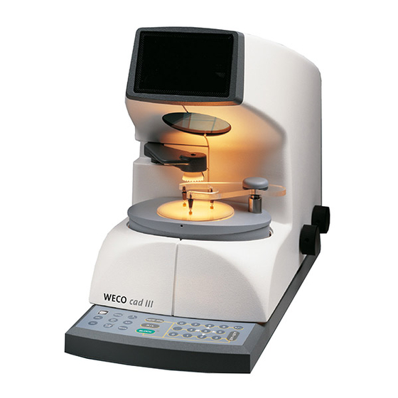
3 Description 3.1 Over view Ill. 1 Main switch (Back side) Adjustment knob for lens illumination Adjustment knob for display contrast Observation window Blocking device Lens adapter Key pad... -
Page 8: Key Pad
3.2 Key pad Abb. 2 <NEW JOB> key To call off new form <WECO> key Reset <R/L> key Right / Left lens <SEND> key No function <BLOCK> key Table goes into <A/P> key No function parallax free position <!>, <"> keys Menu choice or vertical <MODE>... -
Page 9: Display
3.3 Display Abb. 3 Display Graphics: Right / left lens Axiscross (Geometrical form Lens mode centre M) Decentration menu Pattern shape in 1:1 scale Required blank diameter including Minimum blank (circle) edging tolerance Near segment lay-out grid for segment or segment edges. Input fields Formnumber Decentration data (depending on... -
Page 10: Optical Principle
3.4 Optical principle Abb. 4 The user is looking through a partly This imaging of the lens on the display transparent mirror 2 on a LCD that is avoids image shifts or systematical illuminated from the back and tha shows blocking errors since the distance the decentration values and graphics. -
Page 11: Lens Support
3.5 Lens support Abb. 5 The lens is positioned on 3 pins which This geometrical setting ensures that: forms an equilateral triangle on a • During the blocking process only cardanic ring. vertical pressure is applied to the lens The transparent supporting plate is hold which avoids unwanted shifting. -
Page 12: Technical Data / Performance Standards
This software is not standard See operation mode RS232 below. Current loop interface (CL): Operation mode: for operation a WECO Form Tracer and an edger with SM200 memory board is required. Interface with RS232: Operation as RS232 terminal. For operation CAD Blocker software (EPROM), cable and connection to PC program Optolab IV are required. -
Page 13: Accesories
Performance standards The performanc standards can only be guaranteed with the use of original WECO equipment as described in this manual. Maximum lens diameter. Maximum center thickness Maximum edge thickness Blocking accuracy <0.1 Operation speed Blocking actions / h Screen resolution... -
Page 14: Features
• • • • User friendly adjustment to different by use of 9 decentration menues decentration modes. • • • • Comfortable use of foils through use of special foil adapter • • • • Compatible to all Weco CMS- with standard interfaces equipment... -
Page 15: Set-Up
4.2 Electrical connection Note: Please follow safety guidelines (see 1). • Check wether the voltage indicated on the WECO type plate is conform with the local power supplier. • Connect the power supply cable at the back side of the CAD2000. -
Page 16: First Test Run
test run First • Switch on all devices (FormTracer, CAD 2000 and edgers). • Trace the form on the Form Tracer • Call form on CAD2000. The traced form is displayed. When error messages appear (see 8.2) 4.5 address setting Address changes are only required when two machines are used with the same address. -
Page 17: Operation
5 Operation 5.1 Getting started The normal job processing with the CAD 2000 is very easy to learn % press <NEW JOB> NEW JOB % Key <MODE> For single or multi focal lenses. MODE Display " S " Single vision Display "... -
Page 18: Application
Application The <ENTER> Key The <ENTER> Key must be pressed after all data input. The cusrsor will jump to the next input field. When you exit the last input field the decentration value is calculated. When the <ENTER> key is pressed for more than one second the calculation is applied. -
Page 19: Centration Modes
Centration modes Single vision lenses (1) Multifocals (2) / Progressive lenses With the <MODE> key you can select any of the 3 decentration modes. The lens selection mode needs to be selected before the job number is entered since the shape is released when the <MODE> key is pressed. Mode 1: Single Vision Lenses Display "S"... - Page 20 Menu selection in different lens modes In mode 1 and 2 you can select several menu`s that are indicated by capital letters (A, B,..) The selection depends on how the decentration data is applied by the optician. In total there are 9 different decentration menu`s indicated as 1 A 2 C etc.
-
Page 21: Decentration Process
Decentration process The decentration menu`s differ from each other since the decentration process depends on the different lens types. In total, 9 menu`s are available. Decentration menu selection: 6 Menu`s with box measurement decentration (DIN 58 208 bzw. DIN 58 200): 1A, 1C, 1D, 3H, 2A, 2C 3 Menu`s with decentration to frame rim (RAL RG 915) 1B, 2B, 2D... -
Page 22: Menu Description
Menu description Mode 1 for single vision lenses (Display: S) % Menu with features: p R /p L Monocular PD y R /y Vertical decentration to the frame rim % Menu with features: p R /p L Monocular PD y' R /y' L Vertical decentration to frame rim % Menu with features:... - Page 23 % Menu with features: p R /p L Monocular PD vR /v L Vertical decentration Mode 2 for multi focal lenses (Display: M) % Menu with features: q R , q L Near PD h R , h L Segment height from frame rim Segment width Horizontal displacement of the segment % Menu...
- Page 24 % Menu with features: p R , p L Monocular PD h R , h' L segment height from frame rim Segment width Horizontal displacement of the segment Vertical displacement of the segment Mode 3 for progressive lenses (Display: P) % Menu with cursor - or numerical entry: u R /u L...
-
Page 25: Operation Procedure
6 Operation procedure 6.1 Operation procedure in CMS % Operation overview in CMS... -
Page 26: Operation For Single Vision- And Progressive Lenses
6.2 Operation for single vision- and progressive lenses % Press <NEW JOB> key. NEW JOB % Press <MODE> key for lens type selection MODE Display S " Single Vision lenses (Display " M " Multi focal lenses (Display " P " Progressive lenses with foils) % Press <CALCU>... - Page 27 % Enter the form number on the key-pad. The form number is the same as the number that was entered in the tracer during the tracing process. Range of job numberswith memory card SM200: 1 - 234 Range of job numbers with Software Optolab IV: 1 - 999999 % Press <ENTER>...
- Page 28 % Use the <BLOCK> key to position the table in the parallax free BLOCK zone The lens illumination will turn on. % Single vision lens Super impose the optical center on the decentration point Pogressives: Super impose the decentration cross on the decentration point % Check the blank diameter.
-
Page 29: Operation For Bifocal- Or Trifocal Lenses
6.3 Operation for Bifocal- or Trifocal lenses NEW JOB % Press <NEW JOB> key. % Press <MODE> key to select lens mode. MODE Display " M " Multifocal lenses (Display " S " Single vision) (Display " P " Progressive with foils) Note: The <MODE>... - Page 30 % Press <ENTER> key to end data entry. ENTER The right form is displayed. % Enter decentration data on the key pad.The data quantity and type depends on the selected decentration menu.(see 5.5). • Press <ENTER> key to end data entry. % Decentration point and blank diameter are calculated automatically.
-
Page 31: Operation For Proressive Lenses With Foils
6.4 Operation for Proressive lenses with foils % Press <NEW JOB> key. NEW JOB % Press <MODE> key to select lens mode MODE Display " P " Progressive with folis (Display " M " Multifocal lens) (Display " S " Single Vision) Note: Only press <MODE>... - Page 32 % Press <ENTER> key to end data entry. ENTER % The right form is displayed. % Position foils for the right lens with the nasal side to the right in the foil adapter. • Put the foil adapter in the lens holder. % Use the <BLOCK>...
- Page 33 % Use the cursor and <8> and <2> horizontal <4> and <6> vertical to allign the decentration point on the display with the decentration point on the foil. The decentration values " u " and " v " are displayed. % Press.<lower table>...
-
Page 34: Maintenance
• Don`t use any cleaners or solvents. 7.2 Light bulb exchange Spare light: Halogen bulb 12 V / 20 W Weco Ord..-Nr.: 3561-0234 Warning: Before changing the bulb turn off and disconnect machine • Turn the machine on its side on a soft surface. -
Page 35: Fuses
7.3 Fuses WARNING: Before changing fuses turn of machine and unplug electrical plug. % Open shutter right - next to the electrical plug.. % Remove both fuse holders. • Check fuse and replace if required. • Re-mount fuse holders. • Close shutter. -
Page 36: Appendix
8 Appendix 8.1 Measurement values and descriptions The WECO CAD 2000 use values and descriptions according to DIN 58 208 i.e DIN 58 200. To ensure universal operation the values for b', CH, y' and h' have been addded (all measurements in mm.) Abb. - Page 37 Abb 7 h' R /h' L : Segment height measured from lower box line to y' R /y' L: Vertical distance between optical distance centre. (Not lower box line and Z F in segment centre!)
-
Page 38: Error Messages
8.2 Error messages Error Message meaning Correction message The entered drilling coordinate lies Press <C> key – Select drilling E 01 outside the allowable range. coordinate inside the allowable range. The distance of the drilling coordinate Press <C> key – this message is to E 02 is less than 1 mm to the edge. - Page 39 Test pattern in loop test okay. Press <C> key . E 43 Test pattern in loop test faulty. Press <C> key . E 44 The monocular PD value is less than Press <C> key, enter correct value. E 46 half the DBL value. Therefore the decentration point is outside the form.
-
Page 40: Quick Trouble Shooting And Solutions
8.3 Quick trouble shooting and solutions Error Possible cause Solution After switch-on no operation Main plug not connected or Ceck or replace fuse faulty main fuse Plug-in electrical plug Electrical plug not plugged in Replace (see 7.3) machine fuse defective No form can be called-up Edger with memory not Switch on edger...
Need help?
Do you have a question about the cad III and is the answer not in the manual?
Questions and answers