Table of Contents

Related Manuals for Charnwood TS10F


Summary of Contents for Charnwood TS10F
-
Page 1: Operating Instructions
10” TABLE SAW OPERATING INSTRUCTIONS MODEL: TS10F Charnwood Machinery Ltd, Cedar Court, Walker Road, Bardon Hill, Leicestershire, LE67 1TU Tel. 01530 516 926 Fax. 01530 516 929 email: sales@charnwood.net website: www.charnwood.net... -
Page 2: General Safety Rules
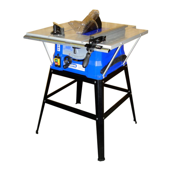
GENERAL SAFETY RULES WARNING: Do not attempt to operate the machine until you have read thoroughly and understood completely all instructions, rules, etc. contained in this manual. Failure to comply may result in accidents involving fire, electric shock, or serious personal injury. Keep this owner's manual and review frequently for continuous safe operation. - Page 3 Risk of Injury. Wear Eye Wear Ear Never reach into Protection Protection a running saw blade Overview of the TS10F Table Saw Extension Table (Left) Mitre Fence Main Table Riving Knife Saw Blade Rip Fence Scale Blade Guard...
- Page 4 TS10F Specification Main Table Size 430mm x 640mm Table Size with Extensions 730mm x 760mm Table Height 890mm Motor (Carbon Brush) 1500W (2hp), 240v Blade Diameter x Kerf x Bore 254mm (10”) x 2.8 x 16mm (5/8”) 0 – 45 degrees...
-
Page 5: Floor Stand Assembly
Layout all of the small parts and check them against the image here. Mitre Guide Blade Guard Rip Fence Carrier Rear Extension Table Side Extension Tables Rip Fence Extrusion Table Support Brackets Riving Knife Front Rail Check the floor stand components against the image here. - Page 6 Attach a long lower brace (C) to the lower holes in the legs. Repeat steps with the remaining legs and long leg brackets. Join the two frames together with the short upper and lower leg brackets. Press a plastic foot onto the end of each of the four legs.
-
Page 7: Saw Assembly
Saw Assembly Attach the Saw to the floor stand Place the saw onto the floor stand and align the four holes in the corners of the base with the holes in the top of the stand. Use four M6 x 25mm hex head bolts, plain washers and nuts, attach the saw to the leg stand. - Page 8 Attach the rear extension table to the main table. Use four M6 x 12mm bolt with spring washer and standard washer. Take the two strengthening bars, place them inside the extension table and insert the bolts into the end of the bar, next to the rounded side of the table.
- Page 9 Ensure that the blade is raised to its highest position and is set to 90 degrees. Loosen the Thumb screw Slide the riving knife down behind the locking plate, so that the locating pin is in the slot. Continue until the locating hole is engaged in the locating pin.
- Page 10 Assemble the Rip Fence Place the Rip Fence Carrier on the front rail of the saw. The carrier can be positioned to the left or right side of the blade as required. Lock the carrier by pressing down on the handle which will clamp it to the front rail.
-
Page 11: Setting Controls
The width of cut is set using the red line on the scale reader. Check the setting by moving the rip fence up to the saw blade and locking the fence in place. The scale should now read zero. If the scale requires any adjustment undo the screw on scale reader and slide the Perspex piece until the scale is set. - Page 12 Blade Height Adjustment The Height Adjustment Handle is used to raise and lower the blade. Turn clockwise to lower the blade and ant-clockwise to raise it. Blade Height Adjustment Hand Wheel Before making a cut, set the blade height so that only the teeth of the blade sit above the piece to be cut.
-
Page 13: Making A Cut
The Mitre Fence The Mitre Fence is usually used when cutting across the grain or for cutting at an angle. Insert the fence into one of the slots in the table. Set the angle by loosening the locking knob and reading off the scale. The fence can be used to the left or right of the blade. -
Page 14: Maintenance
Tighten the 90 degree set screw until it makes contact with the underside of the table Check the setting by tilting the blade away from 90 degrees and then gently back until it stops. Check the angle again, if it is correct, secure this setting by tightening the lock nut. - Page 15 Replacing the Carbon Brushes After every 20 hours of running, it is necessary to check the carbon brushes in the motor for wear. The carbon brushes must be replaced when the carbon block has less than 5mm of material remaining. Failure to replace them in time may cause damage to the motor armature.
-
Page 16: Troubleshooting
Your local refuse amenity will have a separate collection area for EEE goods Declaration of Conformity for CE Marking Charnwood Declare that Circular Saw Bench, Model TS10F Conforms with the following Directives: Machinery Directive 2006/42/EC EMC Directive 2014/30/EU And further conforms to the machinery example for which the EC type examination Certificate No. - Page 17 TS10F Table Saw Parts Drawing TS10F Stand Parts Drawing...
- Page 18 TS10F Parts List Part No. Part No. Description Description Hex Bolt Large Flat Washer Hex Nut Screw Stand Leg Flat Washer Spring Washer Top Leg Bracket A Bottom Leg Bracket B Rubber Foot Top Leg Bracket D Bottom Leg Bracket C...
- Page 19 Screw Cover Screw Blade Spanner A Blade Spanner B Push Stick Clip Screw Push Stick Screw Large Flat Washer Vane Gap Film Holder A Screw Large Flat Washer BRUSH Carbon Brushes (Pair) MOTOR Motor Complete Assembly TS10F Floor Stand Drawing...
- Page 20 Charnwood Machinery Ltd, Cedar Court, Walker Road, Hilltop Industrial Estate, Bardon Hill, Leicestershire, LE67 1TU, England Tel. 01530 516 926 Fax. 01530 516 929 email: sales@charnwood.net website: www.charnwood.net...
Need help?
Do you have a question about the TS10F and is the answer not in the manual?
Questions and answers