
Related Manuals for Charnwood W730


Summary of Contents for Charnwood W730
- Page 1 14” BANDSAW OPERATING INSTRUCTIONS MODEL: W730 Charnwood, Cedar Court, Walker Road, Bardon, Leicestershire, LE67 1TU Tel. 01530 516 926 Fax. 01530 516 929 email; sales@charnwood.net website; www.charnwood.net...
-
Page 2: General Safety Rules
GENERAL SAFETY RULES WARNING: Do not attempt to operate the machine until you have thoroughly read and understood completely all instructions, rules, etc. contained in this manual. Failure to comply may result in accidents involving fire, electric shock, or serious personal injury. Keep this owner's manual and review frequently for continuous safe operation. - Page 3 19. Always wear a face or dust mask if operation creates a lot of dust and/or chips. Always operate the tool in a well ventilated area and provide for proper dust removal. Use a suitable dust extractor. ADDITIONAL RULES FOR BAND SAWS 1.
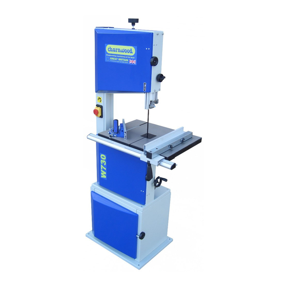
- Page 4 Specification Table size 550 x 400 mm Table height 1000 mm Motor 1100W Blade length 2560 mm Blade widths 6 to 19 mm Blade speeds (no load) 370 and 800 m/min Maximum depth of cut at 90 230 mm Throat capacity 340 mm Dust extractor hose connection 100 mm...
- Page 5 Unpacking Cut the strapping, open the carton and remove all parts from the packaging Assembly Building the base This is most easily accomplished on a bench or table Leave all nuts and bolts finger tight until you have finished assembling this base. Start with right hand side, which has a black knob attached to it.
- Page 6 Bolt the cabinet on to base. Hold the door in position and fix the top hinge to the door frame with a self tapping screw. Do the same with the bottom hinge. Square up the cabinet and tighten all fixing bolts.
- Page 7 Fitting the Saw to the Base Please note that this is a two person operation. You risk serious personal injury and possible damage to the machine if you try to do this single handed. Two people should lift the saw and lower it into place.
- Page 8 This pointer is adjustable if the setscrew is loosened. You may need to make a small adjustment after the table is set perpendicular to the blade. If the table needs to be moved laterally to centre the slot on the blade, loosen these three screws, move the table to the correct position and retighten the bolts.
- Page 9 Screw in and lock the push stick hanger. Hang the push stick on it and remember that this is one of the world’s best finger preservers! Fit the belt tension control handle to the spindle protruding from the front of the lower front face of the saw, noting that the grubscrew in the boss should be opposite the flat on the spindle.
-
Page 10: Setting Up Your Saw
Setting up your saw Quick blade tensioner (shown in tight position). Looking from the front, turn in an anticlockwise direction to slacken Tracking control and lock After ensuring that the quick adjuster is set in the + position, adjust the blade tension with the hand wheel on top of the upper housing. -
Page 11: Changing The Blade
The lower thrust and guide bearing are adjusted similarly. Guide bearing Locking screws Lower thrust bearing adjusting screw Release the belt tension by turning the tension control handle on the front of the lower housing. Move the belt from the larger pulley to the smaller one and then from the smaller to the larger on the other pair. - Page 12 Unplug the bandsaw from the mains socket, slacken off the blade tension and open the upper and lower housing doors. Although there are two micro-switches which will prevent the saw from being started with a door open, disconnection is a good habit to develop. Remove the rip fence carrier.
- Page 14 Parts List A Name Name 001 Lower door 002 Cap head bolt 003 Spacer bush 004 Lock nut 005 Nut 006 Joining block 007 Spring plate 008 Rivet 009 Screw 010 Upper door 011 Circlip 012 Upper bearing bolt 013 Upper bearing bolt support 014 Nut 015 Hex.
- Page 15 103 Fence carrier 104 Plastic pressure plate 105 Self tapping screw 106 Cam 107 Handle 108 Cap 109 Shaft 110 Pointer 111 Cap head bolt 112 End cap, right 113 Rip fence carrier 114 Wing bolt 115 End cap, left 116 Handle 117 Hand wheel 118 Setting collar...
- Page 16 Parts List B – Floorstand Cabinet Name Name B01 Left end panel B02 Nut B03 Front brace B04 Washer B05 Hex head bolt B06 Back panel B07 Right end panel B08 Knob B09 Bolt B10 Base B11 Nut B12 Lock nut B13 Bolt B14 Spacer B15 Door...
Need help?
Do you have a question about the W730 and is the answer not in the manual?
Questions and answers