Table of Contents
Advertisement
Owner's Manual
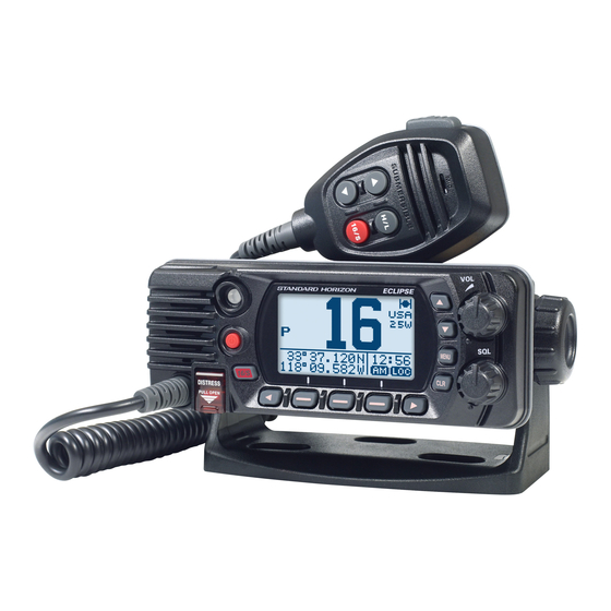
ECLIPSE GPS
GX1400GPS GX1400GPS/E
(
European Version )
ECLIPSE
GX1400
Meets ITU-R M.493-13 class D DSC (Digital Selective Calling)
(European version: Meets ITU-R M.493-14)
Input and Output of GPS information to NMEA 0183 compatible devices
Integrated 66 Channel Internal GPS receiver (GX1400GPS and GX1400GPS/E only)
Built in Separate Receiver for CH70 (Receiving DSC Calls)
Automatic DSC polling of up to 6 ships GPS positions*
Auto DSC channel selection & DSC test call
DSC distress, individual, group, all ships, position request and position report
Large Viewable Display, Easy to Mount, Submersible IPX8 (5 feet or 1.5 m for 30 minutes)
Noise canceling microphone with channel change, 16/S and H/L key buttons
GPS position and time shown on a full dot matrix display*
Preset Key used to recall up to 10 favorite channels
Programmable scan, priority scan, and Multi Watch (Dual Watch or Triple Watch)
Noise cancelling microphone with channel change selection, 16/S and H/L keys
ATIS Mode for European Inland Waterways (GX1400GPS/E only)
*External GPS device required for GX1400.
Advertisement
Table of Contents

Related Manuals for Standard Horizon Eclipse GX1400GPS


Summary of Contents for Standard Horizon Eclipse GX1400GPS
- Page 1 Owner’s Manual ECLIPSE GPS GX1400GPS GX1400GPS/E European Version ) ECLIPSE GX1400 Meets ITU-R M.493-13 class D DSC (Digital Selective Calling) (European version: Meets ITU-R M.493-14) Input and Output of GPS information to NMEA 0183 compatible devices Integrated 66 Channel Internal GPS receiver (GX1400GPS and GX1400GPS/E only) ...
-
Page 2: Table Of Contents
TABLE OF CONTENTS QUICK REFERENCE .......... 2 9 BASIC OPERATION ........24 1 GENERAL INFORMATION ......3 9.1 TURNING ON AND OFF THE 2 PACKING LIST ..........3 TRANSCEIVER .......... 24 3 OPTIONAL ACCESSORIES ......3 9.2 RECEPTION ..........24 4 ONLINE WARRANTY REGISTRATION .. - Page 3 TABLE OF CONTENTS 10.6 POSITION REQUEST ......52 11.4.4 Time Format ..........71 11.4.5 Unit Of Measure ........72 10.6.1 Transmitting a Position Request to 11.4.6 Data Speed ..........72 Another Vessel ......... 52 11.4.7 Output Sentences ........72 10.6.2 Receiving a Position Request ....55 10.6.3 Setting up the Position Request Ringer ...
-
Page 4: Quick Reference
QUICK REFERENCE Press and hold the key to turn on or off the radio. Rotate the VOL knob to adjust the speaker audio volume. Press the [▲] or [▼] key on the radio to select the operating channel. Move the SQL knob clockwise to squelch or counter clockwise to un-squelch the radio. -
Page 5: General Information
1 GENERAL INFORMATION The STANDARD HORIZON GX1400 Marine VHF/FM Marine transceiver is designed to be used in USA, International, and Canadian Marine bands. The GX1400 series can be operated from 11 to 16 VDC and has a switchable RF output power of 1 watt or 25 watts. -
Page 6: Online Warranty Registration
4 ONLINE WARRANTY REGISTRATION Please visit www.standardhorizon.com - Owner’s Corner to register the GX1400 Marine VHF. NOTE: Visiting the STANDARD HORIZON website from time to time may be ben- eficial. When new products are released, information will appear on the website. 5 Safety Precautions (Be Sure to Read) Be sure to read these important precautions, and use this product safely. - Page 7 WARNING Do not power this transceiver with a voltage Use only the specified type fuses. other than the specified power supply voltage. Use of an incorrect fuse may result in fire and A fire, electric shock, or damage may result. equipment failure.
-
Page 8: Getting Started
6 GETTING STARTED 6.1 ABOUT VHF RADIO The radio frequencies used in the VHF marine band lie between 156 and 158 MHz with some shore stations available between 161 and 163 MHz. The marine VHF band provides communications over distances that are essentially “line of sight”... -
Page 9: Distress And Hailing (Channel 16)
To get your coax cable through a fitting and into your boat’s interior, you may have to cut off the end plug and reattach it later. You can do this if you follow the directions that are supplied with the connector. Be sure to make good soldered connections. 6.4 DISTRESS AND HAILING (CHANNEL 16) Channel 16 is known as the Hail and Distress Channel. An emergency is defined as a threat to life or property. -
Page 10: Calling Another Vessel ( Channel 16 Or 9 )
6.5 CALLING ANOTHER VESSEL ( CHANNEL 16 OR 9 ) Channel 16 may be used for initial contact (hailing) with another vessel. However, its most important use is for emergency messages. This channel must be monitored at all times except when actually using another channel. It is monitored by the European, U.S. -
Page 11: Controls And Indicators
7 CONTROLS AND INDICATORS 7.1 FRONT PANEL (Power) key Press and hold to toggle the radio on or off. When the power is turned on, the transceiver is set to the last selected channel. BUSY Indicator Lamp This indicator glows green when the squelch opens. ▲&▼... - Page 12 MENU key Press to access MENU. For details, refer to section “9.5 BASIC OPERA- TION OF THE SETUP MENU”. CLR key Press this key to cancel a MENU selection or functions. Soft keys Press these keys to display the soft keys. The 3 programmable soft keys can be customized by the Setup MENU mode described in section “11.5.4 Soft Keys”.
-
Page 13: Microphone
7.2 MICROPHONE PTT (Push-To-Talk) switch When in radio mode and the PTT switch is pressed, the transmitter is enabled for voice communications to another vessel. ▲ & ▼ key These keys on the microphone are used to select channels and to choose MENU items. -
Page 14: Rear Panel
Connects the transceiver to a GPS chart plotter. Refer to section “8.5.2 Accessory Cables”. EXTERNAL Speaker Connection Cable (White & Shield) Connects the transceiver to an optional external speaker. Refer to section “3 OPTIONAL ACCESSORIES” for a list of optional STANDARD HORIZON Speakers. White: External Speaker (+) Shield: External Speaker (−) -
Page 15: Installation
8 INSTALLATION 8.1 SAFETY / WARNING INFORMATION This radio is restricted to occupational use, work related operations only where the radio operator must have the knowledge to control the exposure conditions of its passengers and bystanders by maintaining the minimum separation distance of 3 feet (1 m). -
Page 16: Optional Mmb-84 Flush Mount Bracket
Desktop Mounting Overhead Mounting 8.3.2 Optional MMB-84 Flush Mount Bracket A GPS receiver and antenna is located in the front panel of the GX1400GPS and GX1400GPS/E. In many cases the radio may be flush mounted, however before cutting holes to flush mount the radio it is recommended to temporarily connect the radio to power and turn on in the location where it will be flush mounted to confirm it is able to receive a GPS location on it’s display. If the radio is not able to receive a location, a GPS Chart plotter with NMEA 0183 output or the optional SCU-38 External GPS Antenna may be needed to receive GPS satellite signals. -
Page 17: Electrical Connections
Bracket Adjusting Screw Lock-washer nut combination 8.4 ELECTRICAL CONNECTIONS CAUTION Reverse polarity connections will damage the radio! Connect the power cord and antenna to the radio. Antenna and Power Supply connections are as follows: 1. Mount the antenna at least 3.28 feet (1 m) away from the radio. At the rear of the radio, connect the antenna cable. -
Page 18: Connection Of External Devices To The Radio
Fuse Replacement To take out the fuse from the fuse holder, hold both ends of the fuse holder and pull the fuse holder apart, do not bend the fuse holder. When you replace the fuse, please confirm that the fuse is tightly fixed on the metal contact located inside the fuse Holder. If the metal contact holding the fuse is loose, the fuse holder may heat up. -
Page 19: Accessory Cables
8.5.2 Accessory Cables The image and table below show the wires of the transceiver and the connections to optional devices such as an external GPS antenna and a GPS chart plotter. CAUTION Care must be taken not to touch any of the NMEA wires to positive 12 VDC or the radio may be damaged. -
Page 20: Gps Input - Optional Scu-31 External Gps Antenna
8.5.4 GPS Input - optional SCU-31 External GPS Antenna External GPS Antenna SCU-31 Radio Wires Yellow: NMEA IN(+) Brown Green: NMEA IN(−) Black Black 2A Fuse (−) 12 V Battery The SCU-31 External GPS antenna (Built-in GPS receiver) is supplied with 49 feet (15 m) of cable and a connector. -
Page 21: Initial Setup Required When Turning On The Power For The First Time
The MMSI can be inputted only once, please be careful not to input the incorrect MMSI number. If the MMSI number need to be reset. Please contact Standard Horizon to obtain the required reset code. Refer to the section “11.5.6 Reset the USER MMSI and ATIS CODE”. -
Page 22: Checking Gps Connections (Gps Status Display)
6. When finished programming the MMSI number, MMSI INPUT 1st: press the [FINISH] soft key. The radio will ask you ********* to input the MMSI number again. Perform steps 4 2nd: 366901234 through 6 above. BACK FINISH SELECT 7. After the second number has been input, press MMSI INPUT the [FINISH] soft key to store the MMSI. - Page 23 The transceiver has a GPS status display which shows GPS STATUS the satellites currently being received, along with a graphical (bar-graph) representation of the relative signal strengths from each of the satellites. 23˚56.890N 09:56 123˚56.890W (GPS S tatuS iSPLay NOTE When the GPS reception is limited, such as the flush mounting of the GX1400GPS and GX1400GPS/E, it is recommended to connect option- al External GPS Antenna SCU-38 to GPS ANT connector on the rear...
-
Page 24: Gps Configuration
8.8 GPS CONFIGURATION 8.8.1 Changing the GPS Time The transceiver shows GPS satellite time or UTC (Universal Time Coordinated) time in factory default. A time offset is needed to show the local time in your area. The time offset must be changed in order for the radio to display the current time in your area. -
Page 25: Changing The Time Format
4. Press the [▲] or [▼] key to select “TIME AREA”, GPS SETUP LOCATION FORMT then press the [SELECT] soft key. TIME OFFSET TIME AREA TIME FORMAT BACK SELECT 5. Press the [▲] or [▼] key to select “UTC” or TIME AREA “LOCAL”. LOCAL BACK ENTER 6. Press the [ENTER] soft key to store the selected setting. 7. -
Page 26: Basic Operation
9 BASIC OPERATION 9.1 TURNING ON AND OFF THE TRANSCEIVER 1. After the transceiver has been installed, ensure that the power supply and antenna are properly connected. key to turn the radio ON. 2. Press and hold the 9.2 RECEPTION 1. -
Page 27: Transmit Time-Out Timer ( Tot )
To switch the TX output power: 1. Press the [H/L] key on the front panel or the micro- BUSY phone to switch between HI (25 W) or LO (1 W) output power. 23˚56.890N 09:56 123˚56.890W NOTE: When the TX output power is set to “Low” BUSY while the transceiver is on channel 13 or 67 (USA Channel group only), the output power will tempo- 23˚56.890N 09:56... -
Page 28: Simplex/Duplex Channel Use
4. Press the [▲] or [▼] key to select the setting item, DSC SETUP then press the [SELECT] soft key. INDIVIDUAL DIR. INDIVIDUAL REPLY INDIVIDUAL ACK INDIVIDUAL RING BACK SELECT 5. Press the [▲] or [▼] key to select the desired setting. INDIVIDUAL DIR. 6. Press the [ENTER] soft key to store the selected EDIT setting. DELETE 7. Press the [CLR] key to return to radio operation. BACK SELECT (The display can also be returned to the previous... -
Page 29: Noaa Weather Channels (In Usa And Canada Only)
9.8 NOAA WEATHER CHANNELS (in USA and Canada only) 1. To receive a NOAA weather channel, press one of BUSY the soft keys, then press the WX soft key from any P-SET channel. The transceiver will go to the last selected weather channel and the “WX”... -
Page 30: Multi Watch (To Priority Channel)
9.9 MULTI WATCH (TO PRIORITY CHANNEL) Multi watch is used to scan two or three channels for communications. • In Dual Watch, a normal VHF channel and the priority channel are scanned alternately. • In Triple Watch, a normal VHF channel, the priority channel, and the sub channel are scanned alternately. -
Page 31: Scanning
NOTE The priority channel or the sub channel may be changed from CH16 (default) or CH9 (default) to another channel. Refer to section “11.2.7 Priority Channel” or “11.2.8 Sub Channel”. 9.10 SCANNING The GX1400 series will automatically scan channels programmed into the preset channel memory and also the scan channel memory, and the last selected weather channel. -
Page 32: Programming Scan Memory
9.10.2 Programming Scan Memory ] “SETUP” “CHANNEL SETUP” “SCAN MEMORY” 2. Press the [▲] or [▼] key to select a desired SCAN MEMORY CH: 16 channel to be scanned, then press the [MEM] CH: 17 soft key. The “MEM” icon appears on the display, CH: 1018 CH: 1019 which indicates the channel has been selected to... -
Page 33: Priority Scanning ( P-Scan )
9.10.4 Priority Scanning ( P-SCAN ) 1. Set the scan type to “PRIORITY SCAN” in the SETUP menu (refer to “9.10.1 Selecting the Scan Type”). 2. Adjust the SQL knob until background noise disappears. 3. Press one of the soft keys, until the [SCAN] soft BUSY P-SCN key display, then press the [ SCAN] soft key. -
Page 34: Operation
4. Press the [ADD] soft key to program the channel BUSY into the preset channel. P-SET 5. Repeat steps 1 through 4 to program the desired channels into the preset channel bank. Up to 10 channels can be registered. If you attempt to register the 11th channel, error beep will sound. 9.11.2 Operation 1. -
Page 35: Digital Selective Calling (Dsc)
10 DIGITAL SELECTIVE CALLING (DSC) 10.1 GENERAL WARNING The GX1400 series is designed to generate digital maritime distress and safety calls to facilitate search and rescue. To be effective as a safety device, this equipment must be used only within communica- tion range of a shore-based VHF marine channel 70 distress and safety watch system. - Page 36 Basic Operation 1. Lift the red spring loaded [DISTRESS] cover, !!DISTRESS!! then press and hold the [DISTRESS] key for 3 UNDESIGNATED seconds. The “DISTRESS” screen will appear on [ DISTRESS ] Hold for 3 sec. the LCD and the radios display will count down QUIT (3-2-1) and then transmit the distress alert.
- Page 37 2. Press the [NATURE] soft key. DIST ALERT MSG UNDESIGNATED The “NATURE OF DIST” menu will appear on the POS: --°--.--- - display. ---°--.--- - TIME: --:--UTC BACK NATURE POS/TM 3. Press the [▲] or [▼] key to select the desired NATUER OF DIST FIRE,EXPLOSION nature of distress category, then press the FLOODING...
- Page 38 Pausing a Distress Alert After a distress alert is transmitted, the distress alert is repeated every 4 minutes until the call is canceled by the user or until the radio is turned off and on again. The transceiver has provision to suspend (pause) the re-transmitting of the distress call by the procedure below.
-
Page 39: Receiving A Distress Alert
10.2.2 Receiving a Distress Alert 1. When a DSC distress alert is received, an emergency alarm sounds. The display will show the MMSI (or name) of the vessel transmitting the distress. 2. Press any key to stop the alarm. 3. On the display you will notice 3 soft key selections. RX DISTRESS YAESU These selections are described below:... -
Page 40: All Ships Call
10.3 ALL SHIPS CALL The all ships call function allows contact to be established with DSC equipped vessels without having their MMSI in the individual calling directory. Also, priority for the call can be designated as “SAFETY” or “URGENCY”. SAFETY Call: This type of call is used to transmit boating safety information to other vessels. -
Page 41: Receiving An All Ships Call
10.3.2 Receiving an All Ships Call 1. When an all ships call is received, an emergency alarm sounds. The display will show the MMSI (or name) of the vessel transmitting the all ships call. 2. Press any key on the radio to stop the alarm. 3. -
Page 42: Individual Call
3. Press the [▲] or [▼] key to select “OFF”, then ALL SHIPS press the ENTER soft key. BACK ENTER 4. Press the [16/S] key or press the [CLR] soft key to return to radio opera- tion mode. If you wish to return to enabling the ringer tone, just repeat the above procedure, pressing the [▲] or [▼] key to select “ON”... -
Page 43: Setting Up Individual Call Reply
6. Repeat steps 4 and 5 until the name is complete. Press the [ ►] key to move to the next space if you want to enter a blank space in the name. If a mistake was made entering in the name, press the [◄ ] or [►] key repeatedly until the wrong letter is highlighted, then press the [▲] or [▼] key to correct the entry. -
Page 44: Setting Up The Individual Call Acknowledgment
2. Press the [▲] or [▼] key to select “AUTO” or INDIVIDUAL REPLY AUTO “MANUAL”, then press the [ENTER] soft key. MANUAL BACK ENTER 3. Press the [16/S] key or press the [CLR] soft key to return to radio opera- tion mode. 10.4.3 Setting up the Individual Call Acknowledgment The transceiver can select either reply message “ABLE” (default) or “UNABLE” when the individual reply setting (described previous section) is set to “AUTO”. - Page 45 4. Press the [▲] or [▼] key to select the operating INTERSHIP CH CH:06 channel you want to communicate on and press CH:08 CH:09 the [SELECT] soft key. CH:10 BACK MANUAL SELECT 5. Press the [YES] soft key to transmit the individual INDIVIDUAL YAESU DSC signal. CATEG: ROUTINE CH: 08 Transmit a Call? 6. After an individual call is transmitted, if the reply INDIVIDUAL YAESU signal is not received, “Waiting for ACK”...
-
Page 46: Receiving An Individual Call
6. After the ninth number has been entered, press the [FINISH] soft key. 7. Press the [▲] or [▼] key to select the operating INTERSHIP CH CH:06 channel you want to communicate on and press CH:08 CH:09 the [SELECT] soft key. CH:10 BACK MANUAL SELECT 8. Press the [YES] soft key to transmit the individual INDIVIDUAL 366901555 DSC signal. CATEG: ROUTINE CH: 08 Transmit a Call? -
Page 47: Setting Up The Individual Call Ringer
5. After accepting the call, press the [ABLE] soft RX INDIVIDUAL YAESU key to switch to the requested channel. (To inform CATEG: ROUTINE CH: 08 that you cannot respond, press the [UNABLE] SINCE: 00:08 soft key.) ABLE UNABLE QUIT 6. Press the [YES] soft key to send an acknowledge- RX INDIVIDUAL YAESU ment. -
Page 48: Group Call
The transceiver has the capability to turn off the individual call ringer. ] “SETUP” “DSC SETUP” “DSC BEEP” 2. Select “DSC BEEP” with the [▲] or [▼] key, then DSC SETUP AUTO CH CHANGE press the [SELECT] soft key. AUTO ACTION TIMER POS UNFIX WAIT DSC BEEP BACK SELECT 3. - Page 49 Group MMSI numbers are not assigned by the FCC or other organizations licensed to assign ship MMSI numbers. The first digit of a group MMSI is always set to “0” by the international rules. All Standard Horizon radios are preset so when programming a group MMSI the first digit is set to “0”. The USCG recommends programming the MID of a ships MMSI into the second, third and fourth digits of the group MMSI as it denotes the area the ship is located in.
-
Page 50: Transmitting A Group Call
8. Select “GROUP MMSI:” with the [▲] or [▼] key, NAME: then press the [SELECT] soft key. YAESU - GP ---- GROUP MMSI: 0-------- BACK FINISH SELECT 9. Press the [▲] or [▼] key to scroll through numbers, GROUP MMSI: 0 to 9. 03--------- 10. Press the [SELECT] soft key to store the number and step to the next digit to the right. BACK FINISH SELECT... - Page 51 4. Press the [▲] or [▼] key to select the operating INTERSHIP CH CH:06 channel you want to communicate on and press CH:08 the [SELECT] soft key. CH:09 CH:10 BACK MANUAL SELECT 5. Press the [YES] soft key to transmit the group GROUP YAESU GP call signal. CATEG: ROUTINE CH: 08 Transmit a Call? 6.
-
Page 52: Receiving A Group Call
7. Press the [▲] or [▼] key to select the operating INTERSHIP CH CH:06 channel you want to communicate on and press CH:08 CH:09 the [SELECT] soft key. CH:10 BACK MANUAL SELECT 8. Press the [YES] soft key to transmit the group GROUP 036690155 call signal. CATEG: ROUTINE CH: 08 Transmit a Call? 9. -
Page 53: Setting Up The Group Call Ringer
6. Press the [▲] or [▼] key to scroll the screen and RX GROUP YAESU see the MMSI (or name) of the calling vessel, CATEG: ROUTINE CH: 08 category of the call and requested operating SINCE: 00:08 channel. ABLE UNABLE QUIT 7. Press the [QUIT] soft key to display the operating channel number of the requested channel. 8. -
Page 54: Position Request
Advancements in DSC have made it possible to poll the location of another vessel and show the position of that vessel on the display of the transceiver. Standard Horizon has taken this feature one step further, if any Standard Horizon GPS is connected to the transceiver, the polled position of the vessel is shown on the display of the GPS chart plotter making it easy to navigate to the location of the polled vessel. - Page 55 6. When the transceiver receives the position from the polled vessel, the transceiver will produce a ringing alarm sound and the position from the polled vessel is sent to a GPS chart plotter via NMEA 0183. (DSC BEEP needs to be enabled to hear alarm.) Press any key to stop the alarm.
- Page 56 3. Press the [▲] or [▼] key to scroll through numbers, NEW ID MMSI: 0 to 9. 3-------- 4. Press the [SELECT] soft key to store the number and step to the next digit to the right. BACK FINISH SELECT 5. Repeat steps 3 and 4 until the MMSI is complete. If a mistake was made entering in the MMSI number, press the [◄ ] or [►] key repeatedly until the wrong number is highlighted, then press the [▲] or [▼] key to correct the entry.
-
Page 57: Receiving A Position Request
10.6.2 Receiving a Position Request When a position request call is received from another vessel, a ringing alarm will sound and “POS REQUEST” will be shown in the LCD. 1. When a position request call is received, the trans- RX POS REQUEST YAESU ceiver will transmit your position to the vessel who POS REPLY... -
Page 58: Transmitting A Dsc Position Report Call
10.7.1 Transmitting a DSC Position Report Call Position Report from Individual / Position Call Directory ] “DSC” “POS REPORT” 2. Press the [▲] or [▼] key to select “HISTORY” or POS REPORT HISTORY “MEMORY”, then press the [SELECT] soft key. MEMORY NEW ID BACK SELECT 3. Press the [▲] or [▼] key to select an individual MEMORY YAESU you want to contact, then press the [SELECT]... -
Page 59: Receiving A Dsc Position Report Call
5. Repeat steps 3 and 4 until the MMSI is complete. If a mistake was made entering in the MMSI number, press the [◄ ] or [►] key repeatedly until the wrong number is highlighted, then press the [▲] or [▼] key to correct the entry. 6. After the ninth number has been entered, press the [FINISH] soft key. 7. Press the [YES] soft key to send your position to POS REPORT 366901555 the selected vessel. -
Page 60: Setting Up A Position Report Ringer
10.7.3 Setting up a Position Report Ringer The transceiver has the capability to turn off the position report ringer. ] “SETUP” “DSC SETUP” “DSC BEEP” 2. Select “POS REPORT” with the [▲] or [▼] key, DSC BEEP GROUP then press the [SELECT] soft key. ALL SHIPS POS REQUEST POS REPORT BACK... -
Page 61: Auto Pos Polling
6. If a mistake was made entering in the position and MMSI/POS INPUT time, press the [◄] or [►] key until the wrong letter POS: 23°56.890 N is highlighted, then press the [▲] or [▼] key to 123°56.890 W TIME: 12:56UTC correct the entry and press the [SELECT] soft key. BACK FINISH SELECT 7. -
Page 62: Selecting Stations To Be Automatically Polled
10.9.3 Selecting Stations to be Automatically Polled ] “DSC” “AUTO POS POLLING” “AUTO POS POLLING” 2. Press the [▲] or [▼] key to select “SELECT ID”, AUTO POS POLLING ACTIVATION START then press the [SELECT] soft key. SELECT ID BACK SELECT 3. Press the [▲] or [▼] key to select the list number, SELECT ID then press the [SELECT] soft key. -
Page 63: Dsc Test Call
To disable the auto position polling, repeat the above procedure, pressing the [▲] or [▼] key to select “STOP” in step 3 above. BUSY The “ ” indicator will appear on the LCD while the auto position polling is activated. 23˚56.890N 09:56 123˚56.890W 10.10 DSC TEST CALL This function is used to contact another DSC equipped vessel to ensure the DSC functions of the radio are operating correctly. -
Page 64: Receiving A Dsc Test Call
DSC Test Call by Manually Entering an MMSI ] “DSC” “TEST CALL” “NEW ID” 2. Press the [▲] or [▼] key to scroll through numbers, NEW ID MMSI: 0 to 9. 3-------- 3. Press the [SELECT] soft key to store the number and step to the next digit to the right. BACK FINISH SELECT 4. -
Page 65: Dsc Log Operation
10.11 DSC LOG OPERATION The GX1400 series logs transmitted DSC calls, received distress calls, and other calls (individual, group, all ships, etc.). The DSC log feature is similar to an answer machine where calls are recorded for review and a “ ” icon will appear on the radio's display. -
Page 66: Reviewing A Logged Other Calls
2. Press the [▲] or [▼] key to select “DISTRESS DSC LOG TRANSMITTED LOG LOG”, then press the [SELECT] soft key. DISTRESS LOG OTHER CALL LOG LOG DELETE BACK SELECT 3. Press the [▲] or [▼] key to select the station (name DISTRESS LOG HORIZON or MMSI number) you want to review. MEMORY SHIPS USCG Note: When there is an unread received call, “... -
Page 67: Deleting Calls From The "Dsc Log" Directory
4. Press the [▲] or [▼] key to scroll the display. RX OTHER LOG INDIVIDUAL 123456789 YAESU RX TM: 12:56 UTC BACK DELETE RX OTHER LOG DATE: 12/JAN CATER: ROUTINE CH: 06 [ Delayed ACK ] BACK DELETE 5. Press the [BACK] soft key to go back to the DSC other call list. 10.11.4 Deleting Calls from the “DSC LOG” Directory ] ... -
Page 68: Setup Menu
11 SETUP MENU 11.1 DSC SETUP 11.1.1 Individual Directory The transceiver has a DSC directory that allows you to store a vessel or person’s name and the MMSI number associated with vessels you wish to transmit individual calls, position requests and position report transmissions. To transmit an individual call you must program this directory with information of the persons you wish to call, similar to a cellular phones telephone directory. -
Page 69: Auto Position Polling Call Type
11.1.6 Auto Position Polling Call Type The transceiver has the capability to automatically track four vessels programmed into the individual directory. This selection allows you to select the call type used in the auto position polling. Refer to section “10.9.1 Setting up the Polling Call Type” for setting. 11.1.7 Auto Position Polling Interval Time The transceiver has the capability to automatically track four vessels programmed into the individual directory. -
Page 70: Weather Alert (Usa Version Only)
11.2.2 Weather Alert (USA version only) This selection is used to enable or disable the NOAA Weather Alert function. ] “SETUP” “CHANNEL SETUP” “WEATHER ALERT” 2. Press the [▲] or [▼] key to select “ON” or “OFF”. WEATHER ALERT 3. Press the [ENTER] soft key to store the selected setting. BACK ENTER 4. -
Page 71: Priority Channel
The ATIS code can be inputted only once, please be careful not to input the incorrect ATIS code. If the ATIS code need to be reset. Please contact Standard Horizon to obtain the required reset code. Refer to the section “15.6.1 Reset the USER MMSI and ATIS CODE”. -
Page 72: Atis Code Setup (Gx1400Gps/E Only)
11.3.1 ATIS Code Setup (GX1400GPS/E only) ] “SETUP” “ATIS SETUP” “ATIS CODE” 2. Press the [◄] or [►] key to select the first number ATIS CODE INPUT 1st: of your ATIS, then press the [SELECT] soft key to ---------- step to the next number. 3. Repeat step 2 to set your ATIS (ten digits). BACK FINISH SELECT 4. -
Page 73: Gps Setup
5. If you want to set the ATIS feature to another channel group, repeat step 2 through . 6. Press the [CLR] key to return to radio operation. NOTE • The “Scan” and “Dual Watch” features are not available on the chan- nel group while the ATIS feature is turned on. •... -
Page 74: Unit Of Measure
11.4.5 Unit Of Measure This menu item sets the display units of speed, distance and altitude. ] “SETUP” “GPS SETUP” “UNIT OF MEASURE” 2. Press the [▲] or [▼] key to select the item to be UNIT OF MEASURE SPEED set, then press the [SELECT] soft key. DISTANCE ALTITUDE BACK ENTER 3. -
Page 75: Configuration Setup
2. Press the [▲] or [▼] key to select the desired NMEA OUT sentence type, then press the [SELECT] soft key. BACK ENTER 3. Press the [▲] or [▼] key to select “ON” or “OFF”. 4. Press the [ENTER] soft key to save the new setting. 5. Repeat steps 2 through 4 to set the other sentences. BACK ENTER 6. -
Page 76: Key Beep
2. Press the [▲] or [▼] key to select the desired level. CONTRAST The contrast level can be set from “00” to “25”. 3. Press the [ENTER] soft key to store the selected level. BACK ENTER 4. Press the [CLR] key to return to radio operation. 11.5.3 Key Beep This section allows the level of the key beep to be adjusted or turned off. ] ... - Page 77 4. Press the [▲] or [▼] key to select the desired key KEY SELECTION NONE function, then press the [ENTER] soft key. WX/CH SCAN Refer to the next page for available functions. DW/TW BACK ENTER 5. Repeat steps 3 and 4 to assign up to 6 functions. 6. To exit this MENU and return to radio operation press the [BACK] soft key. Available functions are: SOFT KEY NUMBERS DISPLAY...
-
Page 78: Reset
6. Press the [CLR] key to return to radio operation. COMPLETE! 11.5.6 Reset the USER MMSI and ATIS CODE If the MMSI number and ATIS* code (*:GX1400GPS/E only) need to be reset. Please contact Standard Horizon to obtain the required reset codes. To request the Reset Code Contact Standard Horizon and confirm the following required information. ● The Information Necessary to obtain the Reset Code •... - Page 79 (See “Checking the Request code” below). ● Contact Information USA/Canada E-mail: marinetech@yaesu.com Telephone: (800) 767-2450 Europe E-mail: service@yaesu.co.uk Telephone: +44 (0)1962 866667 Other Countries Contact the dealer or the distributor. Checking the Request code ] “SETUP” “CONFIGURATION” “RESET” RESET 2.
- Page 80 USER MMSI RESET 3. Press the [▲]/[▼]/[◄]/[►] key to select the <PASS CODE> first digit of the reset password, then press the _ _ _ _ - _ _ _ _ _ [SELECT] soft key to step to the next number. BACK FINISH SELECT 4. Repeat steps 3 until the reset password is complete.
-
Page 81: Maintenance
Ensure that the supply voltage to the transceiver does not exceed 16 VDC or fall below 11 VDC. • Use only STANDARD HORIZON-approved accessories and replacement parts. In the unlikely event of serious problems, please contact your Dealer or our repair facility. -
Page 82: Troubleshooting Chart
12.3 TROUBLESHOOTING CHART SYMPTOM PROBABLE CAUSE REMEDY Transceiver fails to No DC voltage to the a. Check the 12 VDC battery connections and power up. transceiver, or blown the fuse. fuse. b. The VOL knob needs to be rotated clock- wise to turn the radio on. -
Page 83: Channel Assignments
13 CHANNEL ASSIGNMENTS 13.1 GX1400GPS and GX1400 VHF MARINE CHANNEL CHART CHANNEL USE 160.650 Public Correspondence ( Marine Operator ) 156.050 Port Operation and Commercial. 1001 156.050 VTS in selected areas 160.700 Public Correspondence ( Marine Operator ) 156.100 160.750 Public Correspondence ( Marine Operator ) 156.150 U.S. - Page 84 VHF MARINE CHANNEL CHART CHANNEL USE 157.100 161.700 Port operation, ship movement US Coast Guard Liaison and Maritime Safety Information Broadcasts announced on channel 16 (USA) 1022 157.100 Canadian Coast Guard Liaison and Maritime Safety Information Broadcasts announced on channel 16 (Canada) 161.750 Public Correspondence ( Marine Operator ) 157.150 1023...
- Page 85 VHF MARINE CHANNEL CHART CHANNEL USE US, Canada: Non-commercial ( Recre- ational ) , 156.575 International: Port operations and Ship movement Non-commercial ( Inter-ship only ) 156.625 US: Port Operations, Canada: Commercial fishing only, 156.675 International: Inter-ship, Port operations and Ship movement US: Port Operations, Canada: Commercial fishing only, 156.725 International: Inter-ship, Port operations...
-
Page 86: Gx1400Gps/E
13.2 GX1400GPS/E CHANNEL USE TX (MHz) RX (MHz) SIMPLEX/DUPLEX LOW PWR All countries Germany (except Germany) 156.050 160.650 DUPLEX – TELEPHONE NAUTIK 156.100 160.700 DUPLEX – TELEPHONE NAUTIK 156.150 160.750 DUPLEX – TELEPHONE NAUTIK 156.200 160.800 DUPLEX – INTL NAUTIK 156.250 160.850 DUPLEX... - Page 87 CHANNEL USE TX (MHz) RX (MHz) SIMPLEX/DUPLEX LOW PWR All countries Germany (except Germany) 156.825 SIMPLEX – NAUTIK 156.875 SIMPLEX LOW* PORT OPR SHIP-SHIP 156.925 161.525 DUPLEX – INTL NAUTIK 1078 156.925 SIMPLEX – – – 2078 161.525 SIMPLEX – –...
-
Page 88: Specifications
14 SPECIFICATIONS Performance specifications are nominal, unless otherwise indicated, and are subject to change without notice. Measured in accordance with TIA/EIA-603. GENERAL Channels ..........All USA, International and Canadian Normal Input Voltage ............13.8 VDC ±20% Current Drain Standby ..................... 0.3 A Receive (at Maximum AF Output) ............1.2 A Transmit .............. - Page 89 Selectivity (Typical) Spurious and Image Rejection ....75 dB for Voice (70 dB for DSC) Intermodulation and Rejection ....70 dB for Voice (70 dB for DSC) Audio Output ........ 4.5 W (at 4 ohms external speaker output) Audio Response ..........within + 1/–3 of a 6 dB/octave de-emphasis characteristic at 300 to 3000 Hz Frequency Stability (–4°F to +140°F (–20°C to +60°C)) ....±0.0003 % Channel Spacing .................
-
Page 90: Gx1400 Dimensions
14.1 GX1400 DIMENSIONS 5.1" (129 mm) 1.58" (40 mm) 2.86" (72.5 mm) 6.14" (156 mm) 2.36" (60 mm) 1.16" (29.5 mm) 6.63" (168.4 mm) 5.1" (129 mm) 1.58" (40 mm) 2.86" (72.5 mm) 6.14" (156 mm) 2.36" (60 mm) 5.47" (139 mm) 1.16"... -
Page 91: Fcc Radio License Information
15 FCC RADIO LICENSE INFORMATION Standard Horizon radios comply with the Federal Communication Commission (FCC) requirements that regulate the Maritime Radio Service. 15.1 STATION LICENSE An FCC ship station license is no longer required for any vessel traveling in U.S. waters (except Hawaii) which is under 20 meters in length. However, any... -
Page 92: Fcc Notice
NOTICE Unauthorized changes or modifications to this equipment may void compliance with FCC Rules. Any change or modification must be ap- proved in writing by STANDARD HORIZON. NOTICE This equipment has been tested and found to comply with the limits for a Class B digital device, pursuant to Part 15 of the FCC Rules. - Page 93 THIS DEVICE COMPLIES WITH PART 15 OF THE FCC RULES. OPERATION IS SUBJECT TO THE FOLLOWING TWO CONDITIONS: (1) THIS DEVICE MAY NOT CAUSE HARMFUL INTERFERENCE, AND (2) THIS DEVICE MUST ACCEPT ANY INTERFERENCE RECEIVED, INCLUDING INTERFERENCE THAT MAY CAUSE UNDESIRED OPERATION.
- Page 94 Limited Warranty is valid only in the country/region where this product was originally purchased. On-line Warranty Registration: Thank you for buying STANDARD HORIZON products! We are confident your new radio will serve your needs for many years! Please register your product at www.standardhorizon.com - Owner’s Corner...
-
Page 95: Template For The Gx1400 Series
51 mm... - Page 97 EU Declaration of Conformity We, Yaesu Musen Co. Ltd of Tokyo, Japan, hereby declare that this radio equipment GX1400GPS/E is in full compliance with EU Radio Equipment Directive 2014/53/EU. The full text of the Declaration of Conformity for this product is available to view at :// www.yaesu.com/jp/red ATTENTION –...
- Page 98 Copyright 2019 YAESU MUSEN CO., LTD. All rights reserved. No portion of this manual may be reproduced without the permission of YAESU MUSEN CO., LTD. YAESU MUSEN CO., LTD. Tennozu Parkside Building 2-5-8 Higashi-Shinagawa, Shinagawa-ku, Tokyo 140-0002 Japan 1901G-BC YAESU USA Printed in China 6125 Phyllis Drive, Cypress, CA 90630, U.S.A.
Need help?
Do you have a question about the Eclipse GX1400GPS and is the answer not in the manual?
Questions and answers
I have problems with the eclipse GX1400. It powers up, and I can hear two weather stations. That's it, I cannot call or receive anything else. I replaced the antenna. No change. The unit is only a couple years old. What can you tell me?
Can I get a front cover to protect this unit from the weather?