Table of Contents
Advertisement
AP500/AP520/AP521 AcroPack
Serial Communication Module
USER'S MANUAL
ACROMAG INCORPORATED
30765 South Wixom Road
Wixom, MI 48393-7037 U.S.A.
Tel: (248) 295-0310
Fax: (248) 624-9234
Copyright 2016, Acromag, Inc., Printed in the USA.
Data and specifications are subject to change without notice.
8501053D
Advertisement
Table of Contents

Related Manuals for Acromag AcroPack Series


Summary of Contents for Acromag AcroPack Series
- Page 1 AP500/AP520/AP521 AcroPack Serial Communication Module USER’S MANUAL ACROMAG INCORPORATED 30765 South Wixom Road Wixom, MI 48393-7037 U.S.A. Tel: (248) 295-0310 Fax: (248) 624-9234 Copyright 2016, Acromag, Inc., Printed in the USA. Data and specifications are subject to change without notice. 8501053D...
-
Page 2: Table Of Contents
2.4 Field I/O Connector ....................10 Table 2.1 Field I/O Connector Pin Assignments ................11 Table 2.2 Field I/O 68 PinConnector Assignments ..............13 2.5 RS-422/485 Termination (AP521 Only) ................ 17 Acromag, Inc. Tel: 248-295-0310 - 1 - - 1 - http://www.acromag.com... - Page 3 Table 3.13 EFR - Enhanced Feature Register ................37 3.2.15 XON/XOFF-1,2 Registers (R/W) ....................39 3.3 Model Identification ..................... 39 Table 3.14 Model ID ........................39 4.0 SERVICE AND REPAIR ....................40 Acromag, Inc. Tel: 248-295-0310 - 2 - - 2 - http://www.acromag.com www.acromag.com...
- Page 4 5.3.4 EMC Directives ..........................42 5.4 Reliability Prediction ....................43 Table 5.4 MTBF (all models) .........................43 5.5 PCIe Bus Specifications ....................43 CERTIFICATE OF VOLATILITY ..................44 REVISION HISTORY ......................45 Acromag, Inc. Tel: 248-295-0310 - 3 - - 3 - http://www.acromag.com www.acromag.com...
-
Page 5: General Information
The information contained in this manual is subject to change without notice, and Acromag, Inc. (Acromag) does not guarantee its accuracy. Acromag makes no warranty of any kind with regard to this material, including, but not limited to, the implied warranties of merchantability and fitness for a particular purpose. -
Page 6: Acropack Information - All Models
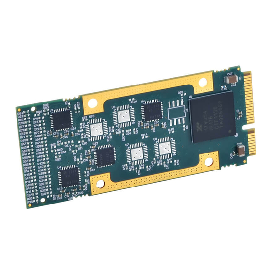
EIA-485 line support. Termination and biasing resistors are installed by default. For non-terminated ports please consult the factory. Figure 1.3 - AP521 Block Diagram Exar 17V358 RS-422/485 RS-422/485 PCIe x1 Ports (8) UART Transceivers (8) Acromag, Inc. Tel: 248-295-0310 - 5 - - 5 - http://www.acromag.com www.acromag.com... -
Page 7: Ordering Information
Individual Modem Control Signals – The AP500 module provides all modem control signals: RTS, CTS, DTR, DSR, DCD, and RI. The AP520 only provides RTS and CTS. Acromag, Inc. Tel: 248-295-0310 - 6 - - 6 - http://www.acromag.com www.acromag.com... -
Page 8: Key Features Pcie Interface
Express Endpoint. 1.4 Signal Interface Products This AcroPack module will mate directly to all Acromag AP carriers. Once connected, the module is accessed via a 50 pin front panel connector. The cables and termination panels are also available. For optimum performance with the AP5XX communication modules, use of the shortest possible length of shielded I/O cable is recommended. -
Page 9: References
USER’S MANUAL AP500/AP520/AP521 ACROPACK 1.6 References The following resources regarding AcroPack modules are available for download on Acromag’s website or by contacting your sales representative. PCI Express MINI Card Electromechanical Specification, REV 1.2 http://www.pcisig.com Exar 17v354 High Performance Quad PCI Express UART datasheet ... -
Page 10: Preparation For Use
It is important that the user employ satisfactory overall system design. It is understood and agreed by the Buyer and Acromag that this is the Buyer's responsibility. -
Page 11: Installation Considerations
Refer to the specifications section for loading and power requirements. Be sure that the system power supplies are able to accommodate the power IMPORTANT: Adequate air requirements of the system boards, plus the installed Acromag board, circulation must be provided to within the voltage tolerances specified. - Page 12 RTS_C* RXD-_C RSVD/ISOL RSVD/ISOL Field I/O 15 RTS_B* CTS_C* RXD+_C Field I/O 16 RXD_B RSVD/ISOL RSVD/ISOL Field I/O 17 DSR_B* TXD_D TXD-_D Field I/O 18 DCD_B* RXD_D TXD+_D Acromag, Inc. Tel: 248-295-0310 - 11 - - 11 - http://www.acromag.com www.acromag.com...
- Page 13 RTS_C* Field I/O 32 RXD_C TXD_G TXD-_G RSVD/ISOL RSVD/ISOL Field I/O 33 DSR_C* RXD_G TXD+_G Field I/O 34 DCD_C* RTS_G* RXD-_G RSVD/ISOL RSVD/ISOL Field I/O 35 CTS_G* RXD+_G Acromag, Inc. Tel: 248-295-0310 - 12 - - 12 - http://www.acromag.com www.acromag.com...
- Page 14 Field I/O 49 No Connect Field I/O 50 No Connect RSVD/ISOL RSVD/ISOL Note: An Asterisk (*) is used to indicate an active-low signal. Table 2.2 Field I/O 68 PinConnector Assignments Acromag, Inc. Tel: 248-295-0310 - 13 - - 13 - http://www.acromag.com www.acromag.com...
- Page 15 RXD-_C RSVD/ISOL RSVD/ISOL Field I/O 15 RTS_B* CTS_C* RXD+_C Field I/O 16 RXD_B RSVD/ISOL RSVD/ISOL Field I/O 17 DSR_B* TXD_D TXD-_D Field I/O 18 DCD_B* RXD_D TXD+_D RSVD/ISOL Acromag, Inc. Tel: 248-295-0310 - 14 - - 14 - http://www.acromag.com www.acromag.com...
- Page 16 RXD_C TXD_G TXD-_G RSVD/ISOL RSVD/ISOL Field I/O 33 DSR_C* RXD_G TXD+_G Field I/O 34 DCD_C* RTS_G* RXD-_G RSVD/ISOL RSVD/ISOL Field I/O 35 CTS_G* RXD+_G Field I/O 36 RI_D* Acromag, Inc. Tel: 248-295-0310 - 15 - - 15 - http://www.acromag.com www.acromag.com...
- Page 17 Field I/O 48 RSVD/ISOL RSVD/ISOL Field I/O 49 No Connect No Connect Field I/O 50 RSVD/ISOL RSVD/ISOL Note: An Asterisk (*) is used to indicate an active-low signal. Acromag, Inc. Tel: 248-295-0310 - 16 - - 16 - http://www.acromag.com www.acromag.com...
-
Page 18: Rs-422/485 Termination (Ap521 Only)
Threaded metric M2.5 screws and spacers are supplied with the AP module to provide additional stability for harsh environments (see Drawing XXX for assembly details). Acromag, Inc. Tel: 248-295-0310 - 17 - - 17 - http://www.acromag.com www.acromag.com... - Page 19 Note 5: The SM bus signals SMB_CLK and SMB_DATA will be used to clock a carrier location serial stream from the carrier, however this is not supported on the AP500/520/521 modules. Note 6: TDI is tied to TDO on the AP500/520/521 modules as they do not use JTAG. Acromag, Inc. Tel: 248-295-0310 - 18 - - 18 - http://www.acromag.com...
-
Page 20: Programming Information
Configuration Address space. This board provides 512 bytes of configuration registers for this purpose. It contains the configuration registers shown in the following table to facilitate Acromag, Inc. Tel: 248-295-0310 - 19 - - 19 - http://www.acromag.com... - Page 21 Only 8K is used, as the upper 8K is for a second 'slave' UART' connected to the master does not exist on the AP5xx module. Acromag, Inc. Tel: 248-295-0310 - 20 - - 20 - http://www.acromag.com...
-
Page 22: Uart And Device Configuration Registers
Read-only Bits [7:0] = 0x00 0x0082 INT2[23:16] Read-only Bits [7:0] = 0x00 0x0083 INT3[31:24] Read-only Bits [7:0] = 0x00 0x0084 TIMERCNTL Read/Write Timer Control Bits [7:0] = 0x00 Acromag, Inc. Tel: 248-295-0310 - 21 - - 21 - http://www.acromag.com www.acromag.com... -
Page 23: Uart Channel Configuration Registers
16550 compatible so their access is limited to 8-bit format. The software driver must separately read the LSR content for the associated error flags before reading the data byte. FIFO Data Loading and Unloading n 32-bit Format Acromag, Inc. Tel: 248-295-0310 - 22 - - 22 - http://www.acromag.com... - Page 24 MSR - Modern Status Register Read-only EFR bit-4= 1 -Auto RS485 Delay Write-only 0x0111 SPR- Scratch Pad Register Read/Write ENHANCED REGISTER 0x1000 FCTR - Feature Control Register Read/Write Acromag, Inc. Tel: 248-295-0310 - 23 - - 23 - http://www.acromag.com www.acromag.com...
-
Page 25: Rhr - Receiver Holding Register (Read Only)
+/-3.125% of the actual center (providing an error margin of 46.875%). Thus, the start bit can begin as much as one 16x clock cycle prior to being detected. Acromag, Inc. Tel: 248-295-0310 - 24 - - 24 - http://www.acromag.com... -
Page 26: Thr - Transmitter Holding Register (Write Only)
14.7456MHz Divisor Baud Rate MCRDIV) 14.7456MHz Baud Rate Divisor x MCRDIV) The MCRDIV term represents the state of bit-7 of the MCR (Mode Control Register) as follows: Acromag, Inc. Tel: 248-295-0310 - 25 - - 25 - http://www.acromag.com www.acromag.com... - Page 27 (based on the 14.7456MHz clock). A different external crystal can replace the 14.7456MHz crystal on the circuit board to obtain unique clock rates. You may contact Acromag Applications Engineering to explore options in this area. With respect to this device, the baud rate may be considered equal to the number of bits transmitted per second (bps).
-
Page 28: Ier - Interrupt Enable Register (R/W)
This interrupt will be issued whenever a fully assembled receive character is available. 0 = Disable Interrupt 1 = Enable Interrupt Modem Status Interrupt. Since the modem input signals Acromag, Inc. Tel: 248-295-0310 - 27 - - 27 - http://www.acromag.com www.acromag.com... -
Page 29: Isr - Interrupt Status Register (Read Only)
The following interrupt source table shows the data values (bit 0-5) for the six prioritized interrupt levels and the interrupt sources associated with each of these interrupts. PRIORITY ISR BITS Source of the Interrupt Table 3.7 Interrupt source Acromag, Inc. Tel: 248-295-0310 - 28 - - 28 - http://www.acromag.com www.acromag.com... -
Page 30: Fcr - Fifo Control Register (Write Only)
When set to “1”, this bit clears all bytes in the Tx-FIFO and resets the counter logic to 0 (this does not clear the shift register). When set to “1”, this bit sets DMA Signal from Mode 0 to Acromag, Inc. Tel: 248-295-0310 - 29 - - 29 - http://www.acromag.com... -
Page 31: Lcr - Line Control Register (Read/Write)
1 0 = 7 Data Bits 1 1 = 8 Data Bits Sel. Stop Bit 0 = 1 Stop Bit Select 1 = 1.5 Stop Bits if 5 data bits; 2 Stop Acromag, Inc. Tel: 248-295-0310 - 30 - - 30 - http://www.acromag.com www.acromag.com... - Page 32 DLM of the baud rate generator or access the Enhanced Feature Register (EFR). Bit 7 must be low to access the Receiver Holding Register (RHR), the Transmitter Holding Register (THR), or the Interrupt Enable Register (IER). A Acromag, Inc. Tel: 248-295-0310 - 31 - - 31 - http://www.acromag.com...
-
Page 33: Mcr - Modem Control Register (R/W)
RX character received will enable Xon. Not Used Must be logic 0 Divide by Four 0 = Divide by one. The crystal frequency is unchanged. 1 = Divide by four. After the crystal Acromag, Inc. Tel: 248-295-0310 - 32 - - 32 - http://www.acromag.com www.acromag.com... -
Page 34: Lsr - Line Status Register (Read/Write-Restricted)
CPU reads the contents of the LSR. In the FIFO mode, the parity error is associated with a particular character in the FIFO (LSR Bit 2 reflects the error when the character is at the top Acromag, Inc. Tel: 248-295-0310 - 33 - - 33 - http://www.acromag.com... - Page 35 Transmitter 0 = Not Empty Empty 1 = Transmitter Empty - set when (TEMT) both the Transmitter Holding Register (THR) and the Transmitter Shift Register (TSR) are both Acromag, Inc. Tel: 248-295-0310 - 34 - - 34 - http://www.acromag.com www.acromag.com...
-
Page 36: Msr - Modem Status Register (Read/Write)
Table 3.12 Modem Status FUNCTION Register CTS - CTS (Set if CTS* has changed states since last read of MSR) DSR - NOT SUPPORTED RI - NOT SUPPORTED. Acromag, Inc. Tel: 248-295-0310 - 35 - - 35 - http://www.acromag.com www.acromag.com... - Page 37 RI (Ring Indicator), DSR (Data Set Ready), and DCD (Data Carrier Detect). A power-up or system reset sets MSR bit-0 to “0” (bit 4 is determined by the corresponding input signal). All other bits are not used. Acromag, Inc. Tel: 248-295-0310 - 36 - - 36 - http://www.acromag.com...
-
Page 38: Scr - Scratch Pad (Read/Write)
Xon1 or Xon2, Xoff1 or Xoff2. 0111 = Transmit Xon2/Xoff2. Receiver compares Xon1 or Xon2, Xoff1 or Xoff2. 1111 = Transmit Xon1 and Xon2, Xoff1 and Xoff2; Receiver compares Xon1 and Xon2, Xoff1 Acromag, Inc. Tel: 248-295-0310 - 37 - - 37 - http://www.acromag.com www.acromag.com... - Page 39 FCTR bits0- 1 are used to set the RTS delay timer/trigger level. 0 = Disable Automatic CTS flow control. Hardware 1 = Enable Automatic CTS flow control. Flow Acromag, Inc. Tel: 248-295-0310 - 38 - - 38 - http://www.acromag.com www.acromag.com...
-
Page 40: Xon/Xoff-1,2 Registers (R/W)
The PCI Device ID and MPIOLVL[0] registers can be used to determine the exact model of the AP5XX module as shown in the table below. Model Device ID MPIOLVL[0] Table 3.14 Model ID 0x0354 0x0358 0x0358 Acromag, Inc. Tel: 248-295-0310 - 39 - - 39 - http://www.acromag.com www.acromag.com... -
Page 41: Service And Repair
SMT repair and service tools are used. For these and other reasons, it is strongly recommended that a non-functioning board be returned to Acromag for repair. Acromag has automated diagnostic and test equipment that thoroughly checks the performance of suspect boards. -
Page 42: Specifications
Note 1: An air cooled application with an AcroPack module will require a minimum airflow of 200LFM. Note 2: A conduction cooled application with an AcroPack module will require purchase of the Heatsink AP-CC-01. Acromag, Inc. Tel: 248-295-0310 - 41 - - 41 - http://www.acromag.com... -
Page 43: Other Environmental Requirements
Conducted RF Immunity (CRFI), per IEC 61000-4-6. Emissions per EN 61000-6-4: Enclosure Port, per CISPR 16. Low Voltage AC Mains Port, per CISPR 16. Note: This is a Class A product Acromag, Inc. Tel: 248-295-0310 - 42 - - 42 - http://www.acromag.com www.acromag.com... -
Page 44: Reliability Prediction
5.5 PCIe Bus Specifications Compatibility Conforms to PCI Express Base Specification, Revision 2.1 Line Speed Gen1 (2.5Gbps) Lane Operation 1-Lane 16K Memory Space Required One Base Address Register Acromag, Inc. Tel: 248-295-0310 - 43 - - 43 - http://www.acromag.com www.acromag.com... -
Page 45: Certificate Of Volatility
Does this product contain Non-Volatile memory (i.e. Memory of whose contents is retained when power is removed) ■ No □ Yes Acromag Representative Name: Title: Email: Office Phone: Office Fax: Russ Nieves Director of solutions@acromag.com 248-295-0310 248-624-9234 Sales and Marketing Acromag, Inc. Tel: 248-295-0310 - 44 - - 44 - http://www.acromag.com www.acromag.com... -
Page 46: Revision History
Corrected shock & vibration specifications 18 JUNE 2018 LMP/MJO Added UART Register Descriptions and 68 pin Connector Pin Assignments 18 SEPT 2018 LMP/MJO Added Reliability Prediction MTBF Table Data Acromag, Inc. Tel: 248-295-0310 - 45 - - 45 - http://www.acromag.com www.acromag.com...
Need help?
Do you have a question about the AcroPack Series and is the answer not in the manual?
Questions and answers