Table of Contents
Advertisement
Quick Links
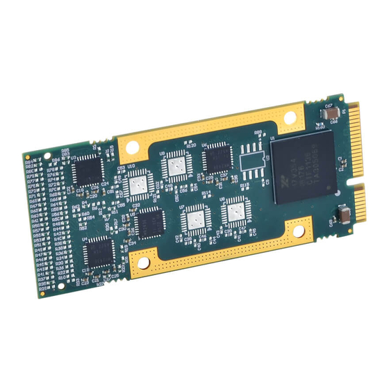
AcroPack Series AP560A
Four Channel CAN Module
USER'S MANUAL
ACROMAG INCORPORATED
30765 South Wixom Road
Wixom, MI 48393-2417 U.S.A.
Tel: (248) 295-0310
Email: solutions@acromag.com
Copyright 2020, Acromag, Inc., Printed in the USA.
Data and specifications are subject to change without notice.
8501173A
Advertisement
Table of Contents

Related Manuals for Acromag AcroPack Series


Summary of Contents for Acromag AcroPack Series
-
Page 1: Control Register
AcroPack Series AP560A Four Channel CAN Module USER’S MANUAL ACROMAG INCORPORATED 30765 South Wixom Road Wixom, MI 48393-2417 U.S.A. Tel: (248) 295-0310 Email: solutions@acromag.com Copyright 2020, Acromag, Inc., Printed in the USA. Data and specifications are subject to change without notice. 8501173A... -
Page 2: Table Of Contents
AcroPack Series AP560 CAN Bus Interface Module Table of Contents GENERAL INFORMATION Intended Audience ..........................5 Preface ..............................5 Trademark, Trade Name and Copyright Information Radio Frequency Interference Statement ..................5 Environmental Protection Statement AP560A OVERVIEW ..........................5 Ordering Information ..........................6 KEY FEATURES ............................ - Page 3 AcroPack Series AP560 CAN Bus Interface Module Firmware Revision Register Location in System Register HI-3111 MODES OF OPERATION ......................28 Initialization Mode Normal Mode Loopback Mode Monitor Mode Sleep Mode CAN PROTOCOL OVERVIEW........................29 BIT ENCODING ............................29 Message Frames ............................ 30...
- Page 4 AcroPack Series AP560 CAN Bus Interface Module Status Flag Register Free Running Timer Command Summary HI-3111 Transmit Buffer ........................59 MESSAGE TRANSMISSION SEQUENCE LOADING THE TRANSMIT FIFO Transmit History FIFO Single Frame Transmission HI-3111 Receive Buffers and Frame Acceptance Filters ................ 63...
-
Page 5: General Information
AP560A OVERVIEW The AcroPack Series AP560A provides four isolated CAN version 2.0B channels capable of 1Mb/s bit rate. The AP560A can be configured to support ARINC 825 and CANaerospace standards. -
Page 6: Ordering Information
AcroPack Series AP560 CAN Bus Interface Module Ordering Information The AcroPack ordering options are given in the following table: Model Operating Temperature Range AP560AE-ISO-LF -40 to +71C 1. Applications requiring operating temperatures of 65°C to 71°C will require purchase of AP-CC-01 AcroPack Conduction Cool Kit (See APPENDIX for installation instructions) with a minimum airflow of 400LFM. -
Page 7: Acropack Module Interface Features
Endpoint. Signal Interface Products This AcroPack module will mate directly to all Acromag AcroPack carriers. Once installed on the carrier, the module is accessed via a front panel connector. The following cable is available for AcroPack carriers with the 68- pin CHAMP connector: Model 5028-609 adapter cable, 7 inches, 68-pin CHAMP 0.8mm to four... -
Page 8: Linux
Acromag AcroPack modules. Linux Acromag provides a software product consisting of Linux software. This software (Model APSW-API-LNX) is composed of Linux libraries for all AcroPack modules, VPX I/O board products, and PCIe I/O Cards. The software is implemented as a library of “C”... -
Page 9: Preparation For Use
It is important that the user employ satisfactory overall system design. It is understood and agreed by the Buyer and Acromag that this is the Buyer's responsibility. WARNING: This board utilizes static sensitive components and should only be handled at a static-safe workstation. -
Page 10: Connectors
AcroPack Series AP560 CAN Bus Interface Module IMPORTANT: Adequate air circulation must be provided to prevent a temperature rise above the maximum operating temperature. The dense packing of the AcroPack module to the carrier/CPU board restricts air flow within the card cage and is cause for concern. Adequate air circulation must be provided to prevent a temperature rise above the maximum operating temperature and to prolong the life of the electronics. - Page 11 AcroPack Series AP560 CAN Bus Interface Module 68 Pin 50 Pin Ribbon Module Field I/O Signal Champ Carrier Champ Carrier Connector Carrier Connector Number Connector RTN0 Reserved/isolation Reserved/isolation Reserved/isolation Reserved/isolation Reserved/isolation Reserved/isolation Reserved/isolation Reserved/isolation Reserved/isolation Reserved/isolation Reserved/isolation Reserved/isolation Reserved/isolation Reserved/isolation...
- Page 12 AcroPack Series AP560 CAN Bus Interface Module 68 Pin 50 Pin Ribbon Module Field I/O Signal Champ Carrier Champ Carrier Connector Carrier Connector Number Connector Reserved/isolation Reserved/isolation RTN1 Reserved/isolation Reserved/isolation Reserved/isolation Reserved/isolation Reserved/isolation Reserved/isolation Reserved/isolation Reserved/isolation Reserved/isolation Reserved/isolation Reserved/isolation Reserved/isolation...
- Page 13 AcroPack Series AP560 CAN Bus Interface Module 68 Pin 50 Pin Ribbon Module Field I/O Signal Champ Carrier Champ Carrier Connector Carrier Connector Number Connector CAN2L Reserved/isolation Reserved/isolation Reserved/isolation RTN2 Reserved/isolation Reserved/isolation Reserved/isolation Reserved/isolation Reserved/isolation Reserved/isolation Reserved/isolation Reserved/isolation Reserved/isolation Reserved/isolation...
- Page 14 AcroPack Series AP560 CAN Bus Interface Module 68 Pin 50 Pin Ribbon Module Field I/O Signal Champ Carrier Champ Carrier Connector Carrier Connector Number Connector Reserved/isolation Reserved/isolation RTN3 Reserved/isolation Reserved/isolation Note: 1. VPX4500-CC-LF is an example of a carrier that uses the ribbon cable connector.
-
Page 15: Logic Interface Connector
AcroPack Series AP560 CAN Bus Interface Module Logic Interface Connector The AP module logic edge connector interfaces to the mating connector on the carrier board. The pin assignments of this connector are standard for all AP modules according to the PCI Express MINI Card Electromechanical Specification, REV 1.2 (with exceptions shown in Table 2 and noted below). - Page 16 AcroPack Series AP560 CAN Bus Interface Module Pin # Name Pin # Name PERST# TDI (UIM_C4) N.C. (W_DISABLE#) TDO (UIM_C8) N.C. (UIM_VPP) RECLK+ N.C. (UIM_RESET) REFCLK- N.C (UIM_CLK) N.C. (UIM_DATA) CLKREQ# N.C. (UIM_PWR) TCK (COEX2) N.C. (+1.5V) TMS (COEX1) N.C. (WAKE#) +3.3V...
-
Page 17: Programming Information
2. PROGRAMMING INFORMATION This Section provides the specific information necessary to program and operate the AP560 module. This Acromag AP560A is a PCI Express Base Specification, Revision 2.1compliant AcroPack module. The carrier/CPU connects a PCIe bus to the AcroPack module. -
Page 18: Memory Map
AcroPack Series AP560 CAN Bus Interface Module The Configuration Registers are accessed via the Configuration Address and Data Ports. The most important Configuration Registers are the Base Address Registers and the Interrupt Line Register which must be read to determine the base address assigned to the AP560A and the interrupt request line that goes active on an AP560A interrupt request. -
Page 19: Can Registers
AcroPack Series AP560 CAN Bus Interface Module BAR0 Base Address Size Description 0x0000_4000→0x0000_4FFF Firmware Revision 0x0000_5000→0x0000_5FFF Reserved 0x0000_6000→0x0000_6FFF Location in System 0x0000_7000→0x0000_7FFF Not Used CAN Registers The CAN Register memory space allows for control of the four independent CAN registers. Table 5 shows the base address for each channel. -
Page 20: Channel X Command Register, (Read/Write) - (Bar0 + Chan X Base + 00H)
AcroPack Series AP560 CAN Bus Interface Module Table 6 Channel Busy Register FUNCTION 15:0 Not Used Channel 0 busy – This read-only bit indicates a message transfer between the FPGA and the Channel 0 CAN controller is in progress. When this bit is a logic “1” the channel is busy. -
Page 21: Channel X Output Message Registers, (Read/Write) - (Bar0 + Chan X Base + 10H Thru 1Ch)
AcroPack Series AP560 CAN Bus Interface Module Table 8 Control Register FUNCTION Frequency Select – selects the frequency of the oscillator input to the CAN controller. This is the f used in the bit rate calculation. 0 – 32 MHz 1 –... -
Page 22: Interrupt Status Register
AcroPack Series AP560 CAN Bus Interface Module registers that allow interrupts to be enabled, queried and cleared under software control over the PCIe bus interface. Table 11 Interrupt Controller Registers BAR0 Base Addr+ Bit(s) Description 0x0000_2000 31:0 Interrupt Status Register... -
Page 23: Interrupt Pending Register
AcroPack Series AP560 CAN Bus Interface Module active. Data bits that are zero have no effect. This allows software to generate interrupts for test purposes. Interrupt Pending Register This Interrupt Pending register (IPR) at BAR0 base address + offset 0x2004 is used to monitor board interrupts. -
Page 24: Interrupt Acknowledge Register
AcroPack Series AP560 CAN Bus Interface Module Interrupt Acknowledge Register The Interrupt Acknowledge register is a write-only location that clears the interrupt request associated with selected interrupt inputs. Note that writing one to a bit in the Interrupt Acknowledge register clears the corresponding bit in Interrupt Status register, and also clears the same bit in the Interrupt Acknowledge register. -
Page 25: Clear Interrupt Enable Register
AcroPack Series AP560 CAN Bus Interface Module 31-4 Reserved Clear Interrupt Enable Register Clear Interrupt Enable register is a location used to clear Interrupt Enable register bits in a single atomic operation, rather than using a read / modify / write sequence. -
Page 26: Axi Xadc Analog To Digital Converter (System Monitor)
AcroPack Series AP560 CAN Bus Interface Module hardware interrupt inputs. Writing a ‘1’ to this bit enables the hardware interrupt inputs and disables software generated inputs. Writing a ‘1’ also disables any further changes to this bit until the device has been reset. -
Page 27: Firmware Revision Register
AcroPack Series AP560 CAN Bus Interface Module Table 20 System Monitor Register Map – (BAR0 + 0x32xx) Address Status Register 0x0000_3200 Temperature 0x0000_3204 V CCINT 0x0000_3208 V CCAUX 0x0000_3280 Maximum Temperature 0x0000_3284 Maximum V CCINT 0x0000_3288 Maximum V CCAUX 0x0000_3290 Minimum Temperature... -
Page 28: Hi-3111 Modes Of Operation
AcroPack Series AP560 CAN Bus Interface Module HI-3111 MODES OF OPERATION The HI-3111 CAN controller supports five modes of operation, namely, Initialization Mode, Normal Mode, Loopback Mode, Monitor Mode and Sleep Mode. Initialization Mode Initialization mode is used to configure the device before normal operation. -
Page 29: Sleep Mode
AcroPack Series AP560 CAN Bus Interface Module Sleep Mode The HI-3111 can be placed in a low power sleep mode if there is no bus activity and the transmit FIFO is empty. In this mode, the internal oscillator and all analog circuitry (transceiver) are off, drawing typically less than 20µA. -
Page 30: Message Frames
AcroPack Series AP560 CAN Bus Interface Module An example of how the bits in a stuffed bit stream might look is shown below. 001010111110000011100000111000 0 = dominant bit, 0 = dominant stuffed bit. 1 = recessive bit, 1 = recessive stuffed bit. - Page 31 AcroPack Series AP560 CAN Bus Interface Module Each data frame is delimited by an End-Of-Frame field (EOF). The EOF consists of seven recessive bits. Following the EOF, there is a gap to the next frame called the Interframe Space (IFS). The IFS consists of two bit fields, Intermission and Bus-Idle. The Intermission consists of three recessive bits;...
- Page 32 AcroPack Series AP560 CAN Bus Interface Module Figure 2 Standard Data Frame - 32 -...
-
Page 33: Extended Data Frame
AcroPack Series AP560 CAN Bus Interface Module Extended Data Frame The extended data frame is shown in Figure 3. In this frame format, SOF is followed by a 32-bit arbitration field consisting of a 29-bit identifier, ID28 - ID0. The first 11 most significant bits of the ID are known as the base identifier. - Page 34 AcroPack Series AP560 CAN Bus Interface Module Figure 3 Extended Data Frame - 34 -...
-
Page 35: Remote Frame
AcroPack Series AP560 CAN Bus Interface Module Remote Frame The remote frame is shown in Figure 4. The function of remote frames is to allow a receiver which periodically receives certain types of data to request that data from the transmitting source. The identifier of the remote frame must be identical to the identifier of the requested transmitting node’s data... - Page 36 AcroPack Series AP560 CAN Bus Interface Module Figure 4 Remote Frame - 36 -...
-
Page 37: Error Frame
AcroPack Series AP560 CAN Bus Interface Module Error Frame The error frame is shown in Figure 5. Any node detecting an error generates an error frame. The error frame consists of two fields, the error flag field and the error delimiter. The type of error flag field depends on the error status of the node, error-active or error-passive (see below). - Page 38 AcroPack Series AP560 CAN Bus Interface Module Figure 5 Error Frame - 38 -...
-
Page 39: Overload Frame
AcroPack Series AP560 CAN Bus Interface Module Overload Frame The overload frame is shown in Figure 6. It has the same format as the active error frame, consisting of an overload flag field and an overload delimiter. The overload flag consists of 6 consecutive dominant bits. This condition violates the rule of bit-stuffing and causes all other nodes on the bus to generate echo flags, similar to the active error flag echoes. -
Page 40: Bit Wise Arbitration
AcroPack Series AP560 CAN Bus Interface Module Figure 6 Overload Frame BIT WISE ARBITRATION The CAN standard resolves data contention on the bus using a scheme called Carrier Sense Multiple Access/Collision Detection-Carrier Resolution (CSMA/CDCR). Carrier Sense: Each node waits for a period without bus activity (bus idle state) before attempting transmission. - Page 41 AcroPack Series AP560 CAN Bus Interface Module Collision Detection: Collisions occur if two nodes attempt to transmit at the same time. Collision Resolution: Collisions are resolved by bitwise arbitration. Highest priority messages (lowest binary identifiers) are sent first without delay and lower-priority messages are automatically re-transmitted later.
-
Page 42: Bit Timing
AcroPack Series AP560 CAN Bus Interface Module BIT TIMING The CAN protocol supports a broad range of bit rates, from a few kHz up to 1MHz (Note: the minimum bit rate of the HI-3111 is limited to 40kHz by the permanent dominant timeout protection of the transceiver). -
Page 43: Phase Buffer Segment 1 And Phase Buffer Segment 2 (Phase Seg1 And Phase Seg2)
AcroPack Series AP560 CAN Bus Interface Module Figure 8 CAN Bit Time Phase Buffer Segment 1 and Phase Buffer Segment 2 (Phase Seg1 and Phase Seg2) The phase buffer segments are used to compensate for phase errors on the bus. Phase Seg1 can be lengthened or Phase Seg2 can be shortened during the re-synchronization bit period automatically by the HI-3111 so that the bit time can be adjusted to account for phase errors. -
Page 44: Phase Errors (E)
AcroPack Series AP560 CAN Bus Interface Module Phase Errors (e) If a bit edge occurs within the Sync Seg as expected, there is no phase error (e = 0). However, if an edge occurs outside Sync Seg, a phase error is deemed to have occurred. -
Page 45: Registers
AcroPack Series AP560 CAN Bus Interface Module REGISTERS Each of the four HI3111 CAN controllers on the AP560A has fourteen register for control and status. The addresses listed in the following table are offsets from each channels’ base address. This section describes the HI-3111 registers. All register bits are active high. -
Page 46: Power-On-Reset
AcroPack Series AP560 CAN Bus Interface Module Power-On-Reset Following power-on, the HI-3111 will automatically perform a Master Reset and return all registers to the default state. Following reset, the device will default to Initialization Mode to allow programming of Control and Bit Timing Registers (see following sections). - Page 47 AcroPack Series AP560 CAN Bus Interface Module 000 - Normal Mode. Normal CAN operation. 001 - Loopback Mode. The transceiver digital input is fed back to the receiver without disturbing the bus. This mode can be used for test purposes, allowing the HI-3111 to receive its own messages.
- Page 48 AcroPack Series AP560 CAN Bus Interface Module Control Register 1 Table 24 CTRL1 (Write 0x16, Read 0xD4) FUNCTION Not used OSCOFF – Oscillator off This bit should be set to a one since the FPGA on the AP560A provides the clock signal.
-
Page 49: Bit Timing Register 0
AcroPack Series AP560 CAN Bus Interface Module BIT Timing Register 0 BTR0 defines the value of the Re-synchronization Jump Width (SJW) and the Baud Rate Prescaler (BRP). This register can be read anytime and written only in init mode (MODE<2:0> bits set to <1xx> in the CTRL0 register). - Page 50 AcroPack Series AP560 CAN Bus Interface Module BIT Timing Register 1 BTR1 configures the CAN protocol bit timing segments in terms of time quanta (Tq) and sets the number of sampling points. This register can be read anytime and written only in init mode (MODE<2:0> bits set to <1xx> in the CTRL0 register).
-
Page 51: Transmit Error Counter Register
AcroPack Series AP560 CAN Bus Interface Module Transmit Error Counter Register The TEC register reflects the current value of the CAN Transmit Error Counter. This register can be written for test purposes. Table 27 TEC (Write 0x26, Read 0xEC) FUNCTION TEC 7:0 –... -
Page 52: Message Status Register
AcroPack Series AP560 CAN Bus Interface Module Message Status Register This register reflects transmission status and which filters were responsible for filtering valid received messages. It is read-only. Table 29 MESSTAT (Read only, 0xDA) FUNCTION TSTAT 1:0 – Transmission Status bits <1:0>... -
Page 53: Error Register
AcroPack Series AP560 CAN Bus Interface Module Error Register The ERR register indicates CAN bus status and protocol errors. It is read only. All bits default to 0 at power up and maintain their status following reset. Bits 4:0 are reset following a host read. -
Page 54: Interrupt Flag Register
AcroPack Series AP560 CAN Bus Interface Module Interrupt Flag Register The Interrupt Flag Register INTF bits will be set by HI-3111 when the corresponding related events described below occur. If individual bits in the Interrupt Enable Register INTE are set, the INT pin will be latched high when any of the corresponding INTF bits are set. -
Page 55: Interrupt Enable Register
AcroPack Series AP560 CAN Bus Interface Module Interrupt Enable Register Setting bits in the Interrupt Enable Register causes a hardware interrupt to be generated at the INT pin when the corresponding bits in the Interrupt Flag Register are set by HI-3111 because of the related events described below. -
Page 56: Status Flag Register
AcroPack Series AP560 CAN Bus Interface Module Status Flag Register The Status Flag Register STATF bits will be set by HI-3111 when the corresponding related events described below occur. Unlike the Interrupt Flag Register, reading this register will NOT clear all bits. These bits are reset automatically by HI-3111 when the described status for each bit changes (e.g. -
Page 57: Free Running Timer
AcroPack Series AP560 CAN Bus Interface Module Free Running Timer A single command reads the16-bit timer value in two data bytes, TIMERUB and TIMERLB. TIMERUB is read first. Table 34 TIMERUB, TIMERLB (Read-only 0xFA) FUNCTION T 15:8 - Free Running Timer Upper Byte, bits <15:8>. - Page 58 AcroPack Series AP560 CAN Bus Interface Module Read Commands Code Data bytes Description Read Mask 6 ID 0xC2 (see Table 40) Read Mask 7 ID 0xC4 (see Table 40) Read Control Register 0 0xD2 (see Control Register 0) Read Control Register 1...
-
Page 59: Hi-3111 Transmit Buffer
AcroPack Series AP560 CAN Bus Interface Module Read Commands Code Data bytes Description Write Filter 4 ID 0x6A (see Table 39) Write Filter 5 ID 0x6C (see Table 39) Write Filter 6 ID 0x6E (see Table 39) Write Filter 7 ID... -
Page 60: Loading The Transmit Fifo
AcroPack Series AP560 CAN Bus Interface Module b) The message is not successful due to lost arbitration or message error. Lost Arbitration: If arbitration is lost, the current message stays in the Transmit Buffer for re- transmission. Message error: Flag BUSERR is set in the Interrupt Flag Register. -
Page 61: Single Frame Transmission
AcroPack Series AP560 CAN Bus Interface Module Figure 9 Simplified Transmission Flow Diagram Single Frame Transmission For single frame transmission, use TX1M, bit 6, Register CTRL1. When using TX1M for single frame transmission, TXEN should be low. Following a successful transmission, TXEN should be reset and the FIFO re-loaded with the next message. - Page 62 AcroPack Series AP560 CAN Bus Interface Module Table 36 Standard Frame Message Offset Bit Description Address Byte Content 0x10 Message Tag 0x11 ID28 to ID21 ID28 ID27 ID26 ID25 ID24 ID23 ID22 ID21 0x12 ID20 to ID18, RTR, ID20 ID19...
-
Page 63: Hi-3111 Receive Buffers And Frame Acceptance Filters
AcroPack Series AP560 CAN Bus Interface Module HI-3111 Receive Buffers and Frame Acceptance Filters Receive Buffers The HI-3111 has an extremely flexible receive buffer and ID filter scheme. Acceptance filters and masks may only be programmed when the device is in Initialization Mode. - Page 64 AcroPack Series AP560 CAN Bus Interface Module FILHIT2:0 bits. As can be seen in Table 41, bits specific to extended frames will be read as zeros for standard frames. If the received data does not contain an 8-byte payload (8 data bytes), the HI-3111 will pad the remaining data bytes with zeros.
- Page 65 AcroPack Series AP560 CAN Bus Interface Module Table 39 Filter ID Format Offset Bit Description Address Byte Content 0x10 FID28 to FID21 FID28 FID27 FID26 FID25 FID24 FID23 FID22 FID21 0x11 FID20 to FID18, RTR, IDE, FID17 to FID15 (Note: FID17 to...
- Page 66 AcroPack Series AP560 CAN Bus Interface Module Table 41 Receive Data Format Offset Bit Description Address Byte Content 0x20 Message Tag (Note This byte does not apply to Temporary Receive Buffer) FILHIT2 FILHIT1 FILHIT0 0x21 Time Tag Upper Byte (Note: This byte only applies to time tag instructions;...
-
Page 67: Programming Interrupts
AcroPack Series AP560 CAN Bus Interface Module Programming Interrupts Interrupts can be enabled for generation by the CAN controllers or events occurring on each of the CAN channels. Legacy interrupts generated by the AP560A use interrupt request line INTA#. Interrupt Programming Example 1. - Page 68 AcroPack Series AP560 CAN Bus Interface Module 9. Enable the AP560A for interrupts again by writing ‘1’ to all the appropriate interrupt enable bits in the Interrupt Controller Interrupt Enable Register. 10. Write “End-Of-Interrupt” command to the system’s interrupt controller.
-
Page 69: Theory Of Operation
AcroPack Series AP560 CAN Bus Interface Module 3. THEORY OF OPERATION This section contains information regarding the hardware of the AP560A. A description of the basic functionality of the circuitry used on the board is also provided. Refer to the Block Diagram in Figure 1 as you review this material. -
Page 70: Service And Repair
SERVICE AND REPAIR ASSISTANCE Surface-Mounted Technology (SMT) boards are generally difficult to repair. It is highly recommended that a non-functioning board be returned to Acromag for repair. The board can be easily damaged unless special SMT repair and service tools are used. Further, Acromag has automated test equipment that thoroughly checks the performance of each board. -
Page 71: Specifications
AcroPack Series AP560 CAN Bus Interface Module 5. SPECIFICATIONS PHYSICAL Height (carrier to top of module components): 8.2 mm (0.32 in). Length x Width: ......70.0 mm x 30.0 mm (2.76 in x 1.18 in). Board Thickness ......1.0 mm (0.039 in). -
Page 72: Reliability Prediction
AcroPack Series AP560 CAN Bus Interface Module Vibration, Random Operating ..Designed to comply with IEC 60068-2-64: 10-500Hz, 5G-rms, 2 Hours/axis Shock, Operating ......Designed to comply with IEC 60068-2-27: 30G, 11ms half sine, 50G, 3mS half sine, 18 shocks at 6 orientations for both test levels... - Page 73 AcroPack Series AP560 CAN Bus Interface Module PCIe Gen 1 (1 lane) Giga bit / second Bytes / second Table 42 PCIe Bus Data Rates Signaling Rate 2.5 Gb/s 312 Mbyte/s Ideal Rate 2 Gb/s 250 Mbyte/s Header Burden plus 4byte 0.332 Gb/s...
-
Page 74: Appendix
AcroPack Series AP560 CAN Bus Interface Module 6. APPENDIX AP-CC-01 Heatsink Kit Installation Hardware Bottom view Top view AP-CC-01 Heat Sink Kit This example will show how to install the AP-CC-01 Heatsink kit with an APCe7020 carrier. - 74 -... - Page 75 AcroPack Series AP560 CAN Bus Interface Module 1. Install two standoffs and secure with two screws. 2. Install the AcroPack module. 3. Install the Heatsink and secure with 4 screws. - 75 -...
- Page 76 AcroPack Series AP560 CAN Bus Interface Module 4. AP-CC-01 Installation is complete. Note: Make sure the thermal pad is contacting the FPGA IC. - 76 -...
-
Page 77: Certificate Of Volatility
AcroPack Series AP560 CAN Bus Interface Module 7. CERTIFICATE OF VOLATILITY Acromag Model Manufacturer: AP560AE-LF Acromag, Inc. 30765 Wixom Rd Wixom, MI 48393 Volatile Memory Does this product contain Volatile memory (i.e. Memory of whose contents are lost when power is removed) ■... -
Page 78: Revision History
AcroPack Series AP560 CAN Bus Interface Module 8. REVISION HISTORY The revision history for this document is summarized in the table below. Release Date Version EGR/DOC Description of Revision 09 SEP 2020 ENZ/ARP Rev A Release. - 78 -...
Need help?
Do you have a question about the AcroPack Series and is the answer not in the manual?
Questions and answers